ASTM D20-20 Standard Test Method for Distillation of Road Tars
Bạn đang xem bản rút gọn của tài liệu. Xem và tải ngay bản đầy đủ của tài liệu tại đây (240.24 KB, 5 trang )
This international standard was developed in accordance with internationally recognized principles on standardization established in the Decision on Principles for the
Development of International Standards, Guides and Recommendations issued by the World Trade Organization Technical Barriers to Trade (TBT) Committee.
Designation: D20 − 20
Standard Test Method for
Distillation of Road Tars1
This standard is issued under the fixed designation D20; the number immediately following the designation indicates the year of original
adoption or, in the case of revision, the year of last revision. A number in parentheses indicates the year of last reapproval. A superscript
epsilon (´) indicates an editorial change since the last revision or reapproval.
This standard has been approved for use by agencies of the U.S. Department of Defense.
1. Scope 4. Significance and Use
1.1 This test method covers the distillation of road tars. 4.1 The distillation test separates tar into fractions according
to a series of specified temperatures.
1.2 The values stated in SI units are to be regarded as
standard. No other units of measurement are included in this 5. Apparatus
standard.
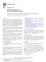
5.1 Flask—A side-arm distillation flask, as shown in Fig. 1,
1.3 This standard does not purport to address all of the conforming to the following dimensions:
safety concerns, if any, associated with its use. It is the
responsibility of the user of this standard to establish appro- Diameter of bulb, outside, mm 86.0 ± 1.5
priate safety, health, and environmental practices and deter- Diameter of neck, inside, mm 22.0 ± 1.0
mine the applicability of regulatory limitations prior to use. Diameter of side-arm, inside, mm 10.0 ± 0.5
Height of flask, outside, mm 131.0 ± 1.5
1.4 This international standard was developed in accor- Vertical distance, bottom of bulb, outside, to 93.0 ± 1.5
dance with internationally recognized principles on standard-
ization established in the Decision on Principles for the horizontal tangent at side-arm, inside, mm 220 ± 5
Development of International Standards, Guides and Recom- Length of side-arm, mm 75 ± 2
mendations issued by the World Trade Organization Technical Angle of side-arm, deg
Barriers to Trade (TBT) Committee. Thickness of side-arm wall, mm 1.0 to 1.5
2. Referenced Documents 5.2 Condenser Tube—A tapered glass condenser, as shown
in Figs. 2 and 3, having the following dimensions:
2.1 ASTM Standards:2
D8055 Guide for Selecting an Appropriate Electronic Ther- Outside diameter of small end, mm 12.5 ± 1.5
Outside diameter of large end, mm 28.5 ± 3.0
mometer for Replacing Mercury Thermometers in D04 Length, mm
Road and Paving Standards Length of uniformly tapered part, mm 360 ± 4
E1 Specification for ASTM Liquid-in-Glass Thermometers 100 ± 5
3. Summary of Test Method 5.3 Source of Heat—A heat source consisting of a bunsen or
meker-type burner (Note 1) or an electric heater. The electric
3.1 A 100-g sample is distilled at a controlled rate from a heater3 shall have an output variable of 750 W and an upper
300-mL flask into tared receivers. The masses of distillate refractory with dimensions as shown in Fig. 4. The temperature
fractions at a series of specified temperatures and of residue at of the heater shall be controlled by a variable transformer or
the maximum specified temperature are determined. If desired, rheostat suitable for the voltage used, and shall be fitted with a
the residue and distillates may be used for further testing. clamp for mounting on a vertical support rod.
1 This test method is under the jurisdiction of ASTM Committee D04 on Road NOTE 1—An artificial gas model used with natural gas has been found
and Paving Materials and is the direct responsibility of Subcommittee D04.43 on to give a uniform and easily controlled source of heat.
Specifications and Test for Tar and Tar Products.
5.4 Flask Shield and Cover for Flame Distillation—A steel
Current edition approved June 1, 2020. Published June 2020. Originally shield (preferably stainless) lined with 3-mm Transite board,
approved in 1911. Last previous edition approved in 2014 as D20 – 03 (2014). DOI: non-asbestos, with two-part cover made from 6-mm Transite
10.1520/D0020-20. board of the form and dimensions shown in Fig. 5.
2 For referenced ASTM standards, visit the ASTM website, www.astm.org, or 5.5 Flask Shield and Cover for Electric Heater
contact ASTM Customer Service at For Annual Book of ASTM Distillation—A steel shield (preferably stainless) fitted with
Standards volume information, refer to the standard’s Document Summary page on
the ASTM website. 3 The Precision Ful-Kontrol 750-W heater with built-in variable transformer
control, available from Precision Scientific Co., Chicago, IL, has been found
satisfactory. This heater is only available for 115 V. 50/60 Hz. If you are aware of
alternative suppliers, please provide this information to ASTM International
Headquarters. Your comments will receive careful consideration at a meeting of the
responsible technical committee,1 which you may attend.
Copyright © ASTM International, 100 Barr Harbor Drive, PO Box C700, West Conshohocken, PA 19428-2959. United States
D20 − 20
FIG. 1 Distillation Flask it can be lowered at least 150 mm. Place the upper refractory
on the heater with the larger opening facing upwards. Set the
mica windows, and a cover of the same construction and flask shield on the upper refractory.
dimensions as those for flame distillation (5.4) except for the
height of the shield (see Fig. 6). 7.1.2 Insert the thermometer through a new and rolled select
quality regular-length cork of suitable size. Position the ther-
5.6 Gauze for Flame Distillation—Two sheets of 1.0-mm mometer and cork in the neck of the flask so that the cork fits
opening wire gauze made of 0.56-mm diameter nickel- tightly and the bottom of the cork is from 23 to 28 mm above
chromium wire measuring a minimum of 125 mm in diameter the lowest point of the junction between the side-arm and the
or (125 by 125 mm) square. neck of the flask. Then adjust the thermometer in the cork so
that the top of the bulb is level with the lowest point of the
5.7 Burner Chimney for Flame Distillation—Construct a juncture between the side-arm and the neck of the flask. Align
cylindrical metal shield approximately 100 mm high, 95 to the stem of the thermometer on the axis of the bulb through the
105 mm in diameter, and having a peephole 25 mm in diameter neck of the flask.
centered about 32 mm below the ring support. The top of the
shield shall be flanged to permit its being suspended from the 7.1.3 When using the flame distillation apparatus, place the
ring support. flask in the flask shield with its bulb resting on the gauze.
Position the burner so that it is directly beneath the point where
5.8 Receivers—Erlenmeyer flasks or beakers having a nomi- the bulb of the flask contacts the gauze. If the electric heater is
nal capacity of 50 to 125 mL, and tared to the nearest 0.1 g. used, place the flask in the flask shield and support the flask so
that its bottom is between 4 and 7 mm above the heating coils.
5.9 Balance and Masses, accurate to 0.1 g.
7.1.4 Connect the condenser tube to the side-arm of the flask
5.10 Thermometer—An ASTM High Distillation Thermom- with a tight cork joint, having the side-arm project 30 to 50 mm
eter having a range from −2 to +400 °C and conforming to the through the cork. The distance from the neck of the flask to the
requirements for Thermometer 8C as prescribed in Specifica- outlet end of the condenser tube shall be between 500 and
tion E1. 600 mm. Support the condenser tube in a position such that it
is in alignment with the side-arm of the flask, and the
NOTE 2—Either a Pt-100 DIN/IEC Class A accuracy rating with either thermometer is vertical. Place the shield cover over the flask
a three- or four-wiring configuration, a Type T thermocouple with a shield around the neck of the flask.
special error limit classification, or a Type K thermocouple would be
likely electronic temperature measurement replacement devices (Guide 8. Procedure
D8055). However, the ASTM 8C is a total immersion thermometer but is
not used as such in this standard. The impact of replacing the currently 8.1 Weigh the flask (along with the thermometer and cork)
used ASTM 8C thermometer with an electronic temperature measurement to the nearest 0.1 g and then weigh 100.0 6 0.1 g of the sample
device (sensor and meter) on test results needs to be evaluated prior to into the flask.
making any changes.
8.2 Apply heat to the flask so that the first drop of distillate
6. Preparation of Sample (oil or water) falls from the end of the condenser tube in 5 to
15 min. Within 2 min after the first drop, adjust the rate of
6.1 Thoroughly stir or otherwise mix the sample immedi- distillation, and subsequently maintain the rate, so that from 50
ately before removing the portion for testing, to ensure that to 70 drops per min fall from the end of the condenser. Warm
such portion will be representative of the sample. If warming is the condenser tube whenever necessary to prevent accumula-
necessary, take care to avoid loss of volatile material. tion of solid distillates in the tube.
7. Preparation of Apparatus 8.3 Collect the distillate fractions in tared receivers, chang-
ing receivers as the thermometer indicates the maximum
7.1 Assemble the apparatus as follows (see Figs. 2 and 3): temperature, corrected as described in 8.4, for each specified
7.1.1 Suspend the burner chimney by its flange from the fraction. The following fractions are usually specified.
support ring, place the specified two sheets of flat wire gauze
on the burner chimney, and place the flask shield on the upper Up to 170 °C
sheet of gauze. In case the electric heater is used, attach the 170 to 235 °C
heater to a vertical support so that at the end of the distillation 235 to 270 °C
270 to 300 °C
Residue at 300 °C
Fractions at other temperatures, such as 170 to 200 °C and
200 to 235 °C, or 300 to 355 °C and residue at 355 °C, are
sometimes required.
8.4 Do not change the position of the thermometer during
the distillation. Make no correction for the emergent stem of
the thermometer, but if the barometric pressure is outside the
range of 756 to 765, adjust (but do not report) the temperature
in accordance with Table 1.
8.5 When the maximum temperature specified for the test is
indicated by the thermometer, immediately remove the flame
2
D20 − 20
FIG. 2 Apparatus Assembly for Flame Distillation
FIG. 3 Apparatus Assembly for Electric Heater Distillation
FIG. 4 Upper Part of Electric Heater
and the flask shield cover; or, when the electric heater is used cool for at least 5 min or until no vapors are visible. Drain any
as a source of heat, immediately remove the flask shield cover oil remaining in the condenser tube into the receiver containing
and lower the heater at least 150 mm. Allow the apparatus to the last fraction.
3
D20 − 20
FIG. 5 Shield and Cover for Flame Distillation
TABLE 1 Adjustment of Distillation Test Temperatures for
Barometric Pressure
Barometric Fractionation Temperatures for Various
Pressure, Barometric Pressure Ranges, °C
mm Hg
786 to 795 172 202 237 272 302 357
776 to 785
766 to 775 171 201 236 271 301 356
756 to 765
746 to 755 171 201 236 271 301 356
736 to 745
726 to 735 170 200 235 270 300 355
716 to 725
706 to 715 169 199 234 269 299 354
696 to 705
686 to 695 169 199 234 269 299 354
676 to 685
666 to 675 168 198 233 268 298 353
656 to 665
646 to 655 168 198 233 267 297 352
636 to 645
626 to 635 167 197 232 267 297 351
616 to 625
606 to 615 167 197 231 266 296 351
596 to 605
166 196 231 265 295 350
166 195 230 265 295 349
165 195 230 264 294 348
FIG. 6 Shield for Use with Electric Heater 165 194 229 264 293 348
8.6 Weigh the receivers containing the distillate fractions to 164 194 228 263 292 347
the nearest 0.1 g. Weigh the flask (with the thermometer in
place) and residue to the nearest 0.1 g. 164 193 228 262 292 346
8.7 Should the fraction to 170 °C contain water, determine 163 193 227 262 291 345
the water volume and calculate the new mass of oil distillate,
assuming that 1 mL of water weighs 1 g. The amount of water 163 192 226 261 290 345
contained in this fraction may be determined by either of the
following methods: 162 191 226 260 290 344
8.7.1 Transfer the fraction, after weighing, to a tube or 162 191 225 260 289 343
cylinder graduated in 0.1 mL. Rinse the receiver several times
with toluene, adding the rinsings to the tube or cylinder residue. If the residue is not completely fluid, heat it carefully
containing the fraction or, to a temperature not exceeding 150 °C by holding the bulb of
the flask over a wire gauze heated by a gas burner or by
8.7.2 The fraction of 170 °C may be collected in a tared immersion in a suitable bath whose temperature does not
graduated cylinder having a flared top. After weighing, add exceed 150 °C. Incline the flask and rotate it so that the fluid
toluene, which will result in a clear separation of the water and residue will flow around the sides, and collect any oils that
oil distillate. have condensed on the upper surfaces of the flask. Mix the
contents of the flask until they are homogeneous. Allow the
8.8 If the residue from distillation is required for further residue to cool to a temperature at which it can be readily
testing, lower the thermometer until its bulb is in the liquid poured from the flask without loss of volatile material and then
pour it into the desired testing equipment or into a suitable
receptacle. Cover the receptacle.
4
D20 − 20
9. Calculation 11.1.1 Repeatability—Duplicate results by the same opera-
tor should be considered suspect if the reported percentage
9.1 Convert the distillation results to a water-free basis, D, differs by more than the “r” value listed in Table 2.
in %, as follows:
D 5 ~F 2 W! 3 @100/~100 2 W!# (1)
Second and subsequent fractions including residue: TABLE 2 Repeatability (r) and Reproducibility (R) for Distillation
Fractions
D 5 F 3 @100/~100 2 W!# (2)
where: Fraction r R
up to 170 °C
F = mass of the fraction or residue, g, and 170 to 235 °C 0.6 1.8
W = millilitres of water, expressed as grams, in the fraction 235 to 275 °C
270 to 300 °C 1.8 5.2
distilling to 170 °C.
2.4 5.0
1.9 4.2
10. Report 11.1.2 Reproducibility—Results submitted by two laborato-
ries should be considered suspect if the reported percentage
10.1 Report the following information: differs by more than the “R” value listed in Table 2.
10.1.1 The results of the distillation test as percentages to
the nearest 0.1 %, based on the mass of water-free material. For NOTE 3—The precision limits given only apply to fractions having
road tars, it is customary to report the total distillate to a series greater than 2.0 % distillate.
of temperatures corresponding to the maxima specified for the
fractions. 12. Keywords
12.1 distillation; road tar
11. Precision
11.1 The following criteria should be used for judging the
acceptability of results at the 95 % probability level:
ASTM International takes no position respecting the validity of any patent rights asserted in connection with any item mentioned
in this standard. Users of this standard are expressly advised that determination of the validity of any such patent rights, and the risk
of infringement of such rights, are entirely their own responsibility.
This standard is subject to revision at any time by the responsible technical committee and must be reviewed every five years and
if not revised, either reapproved or withdrawn. Your comments are invited either for revision of this standard or for additional standards
and should be addressed to ASTM International Headquarters. Your comments will receive careful consideration at a meeting of the
responsible technical committee, which you may attend. If you feel that your comments have not received a fair hearing you should
make your views known to the ASTM Committee on Standards, at the address shown below.
This standard is copyrighted by ASTM International, 100 Barr Harbor Drive, PO Box C700, West Conshohocken, PA 19428-2959,
United States. Individual reprints (single or multiple copies) of this standard may be obtained by contacting ASTM at the above
address or at 610-832-9585 (phone), 610-832-9555 (fax), or (e-mail); or through the ASTM website
(www.astm.org). Permission rights to photocopy the standard may also be secured from the Copyright Clearance Center, 222
Rosewood Drive, Danvers, MA 01923, Tel: (978) 646-2600; />
5
![Standard Test Method for Compressive Strength of Hydraulic Cement Mortars (Using 2-in. or [50-mm] Cube Specimens)](https://media.store123doc.com/images/document/14/rc/yi/medium_yil1395845738.jpg)