ASTM D5453 Standard Test Method for Determination of Total Sulfur in Light Hydrocarbons, Spark Ignition Engine Fuel, Diesel Engine Fuel, and Engine Oil by Ultraviolet Fluorescence
Bạn đang xem bản rút gọn của tài liệu. Xem và tải ngay bản đầy đủ của tài liệu tại đây (338.42 KB, 11 trang )
Designation: D5453 − 12
Standard Test Method for
Determination of Total Sulfur in Light Hydrocarbons, Spark
Ignition Engine Fuel, Diesel Engine Fuel, and Engine Oil by
Ultraviolet Fluorescence
1
This standard is issued under the fixed designation D5453; the number immediately following the designation indicates the year of
original adoption or, in the case of revision, the year of last revision. A number in parentheses indicates the year of last reapproval. A
superscript epsilon (´) indicates an editorial change since the last revision or reapproval.
1. Scope*
1.1 This test method covers the determination of total sulfur
in liquid hydrocarbons, boiling in the range from approxi-
mately 25 to 400°C, with viscosities between approximately
0.2 and 20 cSt (mm
2
/S) at room temperature.
1.2 Three separate interlaboratory studies (ILS) on
precision, and three other investigations that resulted in an
ASTM research report, have determined that this test method is
applicable to naphthas, distillates, engine oil, ethanol, Fatty
Acid Methyl Ester (FAME), and engine fuel such as gasoline,
oxygen enriched gasoline (ethanol blends, E-85, M-85, RFG),
diesel, biodiesel, diesel/biodiesel blends, and jet fuel. Samples
containing 1.0 to 8000 mg/kg total sulfur can be analyzed
(
Note 1).
NOTE 1—Estimates of the pooled limit of quantification (PLOQ) for the
precision studies were calculated. Values ranged between less than 1.0 and
less than 5.0 mg/kg (see Section
8 and 15.1).
1.3 This test method is applicable for total sulfur determi-
nation in liquid hydrocarbons containing less than 0.35 %
(m/m) halogen(s).
1.4 The values stated in SI units are to be regarded as
standard. No other units of measurement are included in this
standard.
1.5 This standard does not purport to address all of the
safety concerns, if any, associated with its use. It is the
responsibility of the user of this standard to establish appro-
priate safety and health practices and determine the applica-
bility of regulatory limitations prior to use. For warning
statements, see
3.1, 6.3, 6.4, Section 7, and 8.1.
2. Referenced Documents
2.1 ASTM Standards:
2
D1298 Test Method for Density, Relative Density, or API
Gravity of Crude Petroleum and Liquid Petroleum Prod-
ucts by Hydrometer Method
D4052 Test Method for Density, Relative Density, and API
Gravity of Liquids by Digital Density Meter
D4057 Practice for Manual Sampling of Petroleum and
Petroleum Products
D4177 Practice for Automatic Sampling of Petroleum and
Petroleum Products
D6299 Practice for Applying Statistical Quality Assurance
and Control Charting Techniques to Evaluate Analytical
Measurement System Performance
3. Summary of Test Method
3.1 A hydrocarbon sample is either directly injected or
placed in a sample boat. The sample or boat, or both, is inserted
into a high temperature combustion tube where the sulfur is
oxidized to sulfur dioxide (SO
2
) in an oxygen rich atmosphere.
Water produced during the sample combustion is removed and
the sample combustion gases are next exposed to ultraviolet
(UV) light. The SO
2
absorbs the energy from the UV light and
is converted to excited sulfur dioxide (SO
2
*). The fluorescence
emitted from the excited SO
2
* as it returns to a stable state,
SO
2
, is detected by a photomultiplier tube and the resulting
signal is a measure of the sulfur contained in the sample.
(Warning—Exposure to excessive quantities of ultraviolet
(UV) light is injurious to health. The operator must avoid
exposing any part of their person, especially their eyes, not
only to direct UV light but also to secondary or scattered
radiation that is present.)
1
This test method is under the jurisdiction of ASTM Committee D02 on
Petroleum Products, Liquid Fuels, and Lubricants and is the direct responsibility of
Subcommittee D02.03 on Elemental Analysis.
Current edition approved Nov. 1, 2012. Published February 2013. Originally
approved in 1993. Last previous edition approved in 2009 as D5453–09. DOI:
10.1520/D5453-12.
2
For referenced ASTM standards, visit the ASTM website, www.astm.org, or
contact ASTM Customer Service at For Annual Book of ASTM
Standards volume information, refer to the standard’s Document Summary page on
the ASTM website.
*A Summary of Changes section appears at the end of this standard
Copyright © ASTM International, 100 Barr Harbor Drive, PO Box C700, West Conshohocken, PA 19428-2959. United States
1
Copyright by ASTM Int'l (all rights reserved); Sat Oct 19 10:33:53 EDT 2013
Downloaded/printed by
Pontifcia Universidade Catlica do Rio Grande do Sul pursuant to License Agreement. No further reproductions authorized.
4. Significance and Use
4.1 Some process catalysts used in petroleum and chemical
refining can be poisoned when trace amounts of sulfur bearing
materials are contained in the feedstocks. This test method can
be used to determine sulfur in process feeds sulfur in finished
products, and can also be used for purposes of regulatory
control.
5. Apparatus
5.1 Furnace—An electric furnace held at a temperature
(1075 6 25°C) sufficient to pyrolyze all of the sample and
oxidize sulfur to SO
2
.
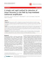
5.2 Combustion Tube—A quartz combustion tube con-
structed to allow the direct injection of the sample into the
heated oxidation zone of the furnace or constructed so that the
inlet end of the tube is large enough to accommodate a quartz
sample boat. The combustion tube must have side arms for the
introduction of oxygen and carrier gas. The oxidation section
shall be large enough (see
Fig. 1) to ensure complete combus-
tion of the sample.
Fig. 1 depicts conventional combustion
tubes. Other configurations are acceptable if precision is not
degraded.
5.3 Flow Control—The apparatus must be equipped with
flow controllers capable of maintaining a constant supply of
oxygen and carrier gas.
5.4 Drier Tube—The apparatus must be equipped with a
mechanism for the removal of water vapor. The oxidation
reaction produces water vapor which must be eliminated prior
to measurement by the detector. This can be accomplished with
a membrane drying tube, or a permeation dryer, that utilizes a
selective capillary action for water removal.
5.5 UV Fluorescence Detector—A qualitative and quantita-
tive detector capable of measuring light emitted from the
fluorescence of sulfur dioxide by UV light.
5.6 Microlitre Syringe—A microlitre syringe capable of
accurately delivering 5 to 20-µL quantities. The needle shall be
50 mm (65 mm) long.
5.7 Sample Inlet System—Either of two types of sample
inlet systems can be used.
5.7.1 Direct Injection—A direct injection inlet system must
be capable of allowing the quantitative delivery of the material
to be analyzed into an inlet carrier stream which directs the
sample into the oxidation zone at a controlled and repeatable
FIG. 1 Conventional Combustion Tubes
D5453 − 12
2
Copyright by ASTM Int'l (all rights reserved); Sat Oct 19 10:33:53 EDT 2013
Downloaded/printed by
Pontifcia Universidade Catlica do Rio Grande do Sul pursuant to License Agreement. No further reproductions authorized.
rate. A syringe drive mechanism which discharges the sample
from the microlitre syringe at a rate of approximately 1 µL/s is
required. For example, see
Fig. 2.
5.7.2 Boat Inlet System—An extended combustion tube
provides a seal to the inlet of the oxidation area and is swept by
a carrier gas. The system provides an area to position the
sample carrying mechanism (boat) at a retracted position
removed from the furnace. The boat drive mechanism will
fully insert the boat into the hottest section of the furnace inlet.
The sample boats and combustion tube are constructed of
quartz. The combustion tube provides a cooling jacket for the
area in which the retracted boat rests awaiting sample intro-
duction from a microlitre syringe. A drive mechanism which
advances and withdraws the sample boat into and out of the
furnace at a controlled and repeatable rate is required. For
example, see
Fig. 3.
5.8 Refrigerated Circulator—An adjustable apparatus ca-
pable of delivering a coolant material at a constant temperature
as low as 4°C could be required when using the boat inlet
injection method (optional).
5.9 Strip Chart Recorder, (optional).
5.10 Balance, with a precision of 60.01 mg (optional).
6. Reagents
6.1 Purity of Reagents—Reagent grade chemicals shall be
used in tests. Unless otherwise indicated, it is intended that all
reagents shall conform to the specifications of the Committee
on Analytical Reagents of the American Chemical Society,
where such specifications are available.
3
Other grades may be
used, provided it is first ascertained that the reagent is of
sufficiently high purity to permit its use without lessening the
accuracy of the determination.
6.2 Inert Gas—Argon or helium only, high purity grade
(that is, chromatography or zero grade), 99.998 % minimum
purity, moisture 5 ppm w/w maximum.
6.3 Oxygen—High purity (that is, chromatography or zero
grade), 99.75 % minimum purity, moisture 5 ppm w/w
maximum, dried over molecular sieves. (Warning—
Vigorously accelerates combustion.)
6.4 Toluene, Xylenes, Isooctane , reagent grade (other sol-
vents similar to those occurring in samples to be analyzed are
also acceptable). Correction for sulfur contribution from sol-
vents (solvent blank) used in standard preparation and sample
specimen dilution is required. Alternatively, use of a solvent
with nondetectable level of sulfur contamination relative to the
sulphur content in the sample unknown makes the blank
correction unnecessary. (Warning—Flammable solvents.)
6.5 Dibenzothiophene, FW184.26, 17.399 % (m/m) S (
Note
2).
3
Reagent Chemicals, American Chemical Society Specifications, American
Chemical Society, Washington, DC. For Suggestions on the testing of reagents not
listed by the American Chemical Society, see Annual Standards for Laboratory
Chemicals, BDH Ltd., Poole, Dorset, U.K., and the United States Pharmacopeia
and National Formulary, U.S. Pharmacopeial Convention, Inc. (USPC), Rockville,
MD.
FIG. 2 Direct Inject Syringe Drive
D5453 − 12
3
Copyright by ASTM Int'l (all rights reserved); Sat Oct 19 10:33:53 EDT 2013
Downloaded/printed by
Pontifcia Universidade Catlica do Rio Grande do Sul pursuant to License Agreement. No further reproductions authorized.
6.6 Butyl Sulfide, FW146.29, 21.92 % (m/m) S (Note 2).
6.7 Thionaphthene (Benzothiophene) , FW134.20, 23.90 %
(m/m) S (
Note 2).
NOTE 2—A correction for chemical impurity can be required.
6.8 Quartz Wool, or other suitable absorbent material that is
stable and capable of withstanding temperatures inside the
furnace (see
Note 3).
NOTE 3—Materials meeting the requirements in 6.8 provide a more
uniform injection of the sample into the boat by wicking any remaining
drops of the sample from the tip of the syringe needle prior to introduction
of the sample into the furnace. Consult instrument manufacturer recom-
mendations for further guidance.
6.9 Sulfur Stock Solution, 1000 µg S/mL—Prepare a stock
solution by accurately weighing approximately 0.5748 g of
dibenzothiophene or 0.4562 g of butyl sulfide or 0.4184 g of
thionaphthene into a tared 100 mL volumetric flask. Dilute to
volume with selected solvent. This stock can be further diluted
to desired sulfur concentration (
Notes 4-7).
NOTE 4—Working standards that simulate or match the composition or
matrix of the samples analyzed can reduce test result bias between direct
inject and boat sample inlet systems.
N
OTE 5—Working standards should be remixed on a regular basis
depending upon frequency of use and age. Typically, stock solutions have
a useful life of about 3 months.
N
OTE 6—Calibration standards can be prepared and diluted on a
mass/mass basis when result calculations are adjusted to accommodate
them.
N
OTE 7—Calibration standards from commercial sources can be used if
checked for accuracy and if precision is not degraded.
6.10 Quality Control (QC) Samples , preferably are portions
of one or more liquid petroleum materials that are stable and
representative of the samples of interest. These QC samples
can be used to check the validity of the testing process as
described in Section
14.
7. Hazards
7.1 High temperature is employed in this test method. Extra
care must be exercised when using flammable materials near
the oxidative pyrolysis furnace.
8. Sampling
8.1 Obtain a test unit in accordance with Practice
D4057 or
Practice D4177. To preserve volatile components which are in
some samples, do not uncover samples any longer than
necessary. Samples shall be analyzed as soon as possible after
taking from bulk supplies to prevent loss of sulfur or contami-
nation due to exposure or contact with sample container.
(Warning—Samples that are collected at temperatures below
room temperature can undergo expansion and rupture the
container. For such samples, do not fill the container to the top;
leave sufficient air space above the sample to allow room for
expansion.)
8.2 If the test unit is not used immediately, then thoroughly
mix in its container prior to taking a test specimen.
FIG. 3 Boat Inlet System
D5453 − 12
4
Copyright by ASTM Int'l (all rights reserved); Sat Oct 19 10:33:53 EDT 2013
Downloaded/printed by
Pontifcia Universidade Catlica do Rio Grande do Sul pursuant to License Agreement. No further reproductions authorized.
9. Preparation of Apparatus
9.1 Assemble and leak check apparatus according to manu-
facturer’s instructions.
9.2 Adjust the apparatus, depending upon the method of
sample introduction, to meet conditions described in
Table 1.
9.3 Adjust the instrument sensitivity and baseline stability
and perform instrument blanking procedures following manu-
facturer’s guidelines.
10. Calibration and Standardization
10.1 Based on anticipated sulfur concentration, select one of
the suggested curves outlined in
Table 2. Narrower ranges than
those indicated may be used, if desired. However, the test
method precision using narrower ranges than those indicated
have not been determined. Ensure the standards used for
calibration bracket the concentrations of the samples being
analyzed. Carefully prepare a series of calibration standards
accordingly. Make other volumetric dilutions of the stock
solution to cover the various ranges of operation within these
calibration curve guidelines. The number of standards used per
curve can vary, if equivalent results are obtained.
10.2 Flush the microlitre syringe several times with the
sample prior to analysis. If bubbles are present in the liquid
column, flush the syringe and withdraw a new sample.
10.3 A sample injection size recommended for the curve
selected from
Table 2 shall be quantitatively measured prior to
injection into the combustion tube or delivery into the sample
boat for analysis (
Notes 8-10). There are two alternative
techniques available.
NOTE 8—Injection of a constant or similar sample size for all materials
analyzed in a selected operating range promotes consistent combustion
conditions.
N
OTE 9—Injection of 10 µL of the 100 ng/µL standard would establish
a calibration point equal to 1000 ng or 1.0 µg.
N
OTE 10—Other injection sizes can be used when complete sample
combustion is not compromised and accuracy/precision are not degraded.
10.3.1 The volumetric measurement of the injected material
can be obtained by filling the syringe to the selected level.
Retract the plunger so that air is aspirated and the lower liquid
meniscus falls on the 10 % scale mark and record the volume
of liquid in the syringe. After injection, again retract the
plunger so that the lower liquid meniscus falls on the 10 %
scale mark and record the volume of liquid in the syringe. The
difference between the two volume readings is the volume of
sample injected (
Note 11).
NOTE 11—An automatic sampling and injection device can be used in
place of the described manual injection procedure.
10.3.2 Fill the syringe as described in 10.3.1. Weigh the
device before and after injection to determine the amount of
sample injected. This procedure can provide greater accuracy
than the volume delivery method, provided a balance with a
precision of 60.01 mg is used.
10.4 Once the appropriate sample size has been measured
into the microlitre syringe, promptly and quantitatively deliver
the sample into the apparatus. Again, there are two alternative
techniques available.
10.4.1 For direct injection, carefully insert the syringe into
the inlet of the combustion tube and the syringe drive. Allow
time for sample residues to be burned from the needle (Needle
Blank). Once a stable baseline has reestablished, promptly start
the analysis. Remove syringe once the apparatus has returned
to a stable baseline.
10.4.2 For the boat inlet, quantitatively discharge the con-
tents of the syringe into the boat containing quartz wool or
suitable equivalent (see
6.8) at a slow rate being careful to
displace the last drop from the syringe needle. Remove the
syringe and promptly start the analysis. The instrument base-
line shall remain stable until the boat approaches the furnace
and vaporization of the sample begins. Instrument baseline is
to be reestablished before the boat has been completely
withdrawn from the furnace (
Note 12). Once the boat has
reached its fully retracted position, allow at least 1 min for
cooling before the next sample injection (
Note 12).
NOTE 12—Slowing boat speed or briefly pausing the boat in the furnace
can be necessary to ensure complete sample combustion. Direct injection
can ease sample handling and improve sample combustion characteristics
for materials containing very volatile sulfur compounds.
10.4.3 The level of boat cooling required and the onset of
sulfur detection following sample injection are directly related
to the volatility of the materials analyzed. For volatile
materials, effective cooling of the sample boat prior to sample
injection is essential. The use of a refrigerated circulator to
minimize the vaporization of the sample until the boat begins
approaching the furnace or an increased time for boat cooling
can be required.
10.5 Calibrate the instrument using one of the following two
techniques.
10.5.1 Perform measurements for the calibration standards
and blank using one of the procedures described in
10.2 – 10.4.
Measure the calibration standards and blank three times.
Subtract the average response of the blank injections from each
calibration standard response. Then determine the average
integrated response of each concentration (see
6.4). Construct
a curve plotting of the average integrated detector response (
y-axis) versus micrograms of sulfur injected (x-axis) (
Note 13).
TABLE 1 Typical Operating Conditions
Syringe drive (direct inject) drive rate (700–750) 1 µL/s
Boat drive (boat inlet) drive rate (700–750) 140–160 mm/min
Furnace temperature 1075 ± 25°C
Furnace oxygen flowmeter setting (3.8–4.1) 450–500 mL/min
Inlet oxygen flowmeter setting (0.4–0.8) 10–30 mL/min
Inlet carrier flowmeter setting (3.4–3.6) 130–160 mL/min
TABLE 2 Typical Sulfur Calibration Ranges and Standard
Concentrations
Curve I Curve II Curve III
Sulfur, ng/µL Sulfur, ng/µL Sulfur, ng/µL
0.50 5.00 100.00
1.00 25.00 500.00
2.50 50.00 1000.00
5.00 100.00
10.00
Injection Size Injection Size Injection Size
10–20 µL 5–10 µL 5 µL
D5453 − 12
5
Copyright by ASTM Int'l (all rights reserved); Sat Oct 19 10:33:53 EDT 2013
Downloaded/printed by
Pontifcia Universidade Catlica do Rio Grande do Sul pursuant to License Agreement. No further reproductions authorized.
This curve shall be linear and system performance must be
checked each day of use. See Section
14.
NOTE 13—Other calibration curve techniques can be used when
accuracy and precision are not degraded.
10.5.2 If the apparatus features self calibration routine,
measure the calibration standards and blank three times using
one of the procedures described in
10.2 – 10.4. If blank
correction is required and is not an available instrument option
(see
6.4 or 10.5.1), calibrate the analyzer in accordance with
manufacturer’s instructions to yield results expressed as nano-
grams of sulfur (
Note 13). This curve shall be linear and system
performance must be checked with each day of use (see
Section
14).
10.6 If analyzer calibration is performed using a different
calibration curve than listed in
Table 2, select an injection size
based on the curve closest in concentration to the measured
solution(s). Construct the calibration curve to yield values that
can be used to report sulfur content on a mass/mass basis.
11. Procedure
11.1 Obtain a test specimen using the procedure described
in Section
8. The sulfur concentration in the test specimen must
be less than the concentration of the highest standard and
greater than the concentration of the lowest standard used in
the calibration. If required, a dilution can be performed on
either a weight or volume basis.
11.1.1 Gravimetric Dilution (mass/mass)— Record the mass
of the test specimen and the total mass of the test specimen and
solvent.
11.1.2 Volumetric Dilution (mass/volume)— Record the
mass of the test specimen and the total volume of the test
specimen and solvent.
11.2 Measure the response for the test specimen solution
using one of the procedures described in
10.2 – 10.4.
11.3 Inspect the combustion tube and other flow path
components to verify complete oxidation of the test specimen.
11.3.1 Direct Inject Systems—Reduce the sample size or the
rate of injection, or both, of the specimen into the furnace if
coke or sooting is observed.
11.3.2 Boat Inlet Systems—Increase the residence time for
the boat in the furnace if coke or soot is observed on the boat.
Decrease the boat drive introduction rate or specimen sample
size, or both, if coke or soot is observed on the exit end of the
combustion tube.
11.3.3 Cleaning and Recalibration—Clean any coked or
sooted parts per manufacturer’s instructions. After any clean-
ing or adjustment, assemble and leak check the apparatus.
Repeat instrument calibration prior to reanalysis of the test
specimen.
11.4 To obtain one result, measure each test specimen
solution three times and calculate the average detector re-
sponses.
11.5 Density values needed for calculations are to be
measured using Test Methods
D1298, D4052, or equivalent, at
the temperature at which the sample was tested.
12. Calculation
12.1 For analyzers calibrated using a standard curve, calcu-
late the sulfur content of the test specimen in parts per million
(ppm) as follows:
Sulfur, ppm
~
µg/g
!
5
~
I 2 Y
!
S 3 M 3 K
g
(1)
or,
Sulfur, ppm µg/g 5
I 2 Y 1000
S 3 V 3 K
v
(2)
where:
D = density of test specimen solution, g/mL,
I = average of integrated detector response for test
specimen solution, counts,
K
g
= gravimetric dilution factor, mass of test specimen/
mass of test specimen and solvent, g/g,
K
v
= volumetric dilution factor, mass of test specimen/
volume of test specimen and solvent, g/mL,
M = mass of test specimen solution injected, either
measured directly or calculated from measured
volume injected and density, V × D,g,
S = slope of standard curve, counts/µg S,
V = volume of test specimen solution injected, either
measured directly or calculated from measured
mass injected and density, M/D, µL, and
Y = y-intercept of standard curve, counts,
1000 = factor to convert µL to mL.
12.2 For analyzers calibrated using self calibration routine
with blank correction, calculate the sulfur in the test specimen
in parts per million (ppm) as follows:
Sulfur, ppm
~
µg/g
!
5
G 3 1000
M 3 K
g
(3)
or,
Sulfur, ppm
~
µg/g
!
5
G 3 1000
V 3 D
(4)
where:
D = density of test specimen solution, mg/µL (neat
injection), or concentration of solution, mg/µL (volu-
metric dilute injection),
K
g
= gravimetric dilution factor, mass of test specimen/
mass of test specimen and solvent, g/g,
M = mass of test specimen solution injected, either mea-
sured directly or calculated from measured volume
injected and density, V × D, mg,
V = volume of test specimen solution injected, either
measured directly or calculated from measured mass
injected and density, M/D, µL,
G = sulfur found in test specimen, µg, and
1000 = factor to convert µg/mg to µg/g.
13. Report
13.1 For results equal to or greater than 10 mg/kg, report the
sulfur result to the nearest mg/kg. For results less than 10
mg/kg, report the sulfur result to the nearest tenth of a mg/kg.
State that the results were obtained according to Test Method
D5453.
D5453 − 12
6
Copyright by ASTM Int'l (all rights reserved); Sat Oct 19 10:33:53 EDT 2013
Downloaded/printed by
Pontifcia Universidade Catlica do Rio Grande do Sul pursuant to License Agreement. No further reproductions authorized.
14. Quality Control
14.1 Confirm the performance of the instrument or the test
procedure by analyzing a quality control (QC) sample (
6.10)
after each calibration and at least each day of use thereafter
(see
10.5).
14.1.1 When QC/Quality Assurance (QA) protocols are
already established in the testing facility, these can be used
when they confirm the reliability of the test result.
14.1.2 When there is no QC/QA protocol established in the
testing facility,
Appendix X1 can be used as the QC/QA
system.
15. Precision and Bias
15.1 The test method was examined in six separate research
reports.
4
(1) RR:D02-1307 (1992) original with multiple matrices,
(2) RR:D02-1456 (1999) UVF/X-ray equivalence study,
(3) RR:D02-1465 (1997) gasoline and RFG only,
(4) RR:D02-1475 (1998) low level gasoline, diesel, and
biodiesel,
(5) RR:D02-1547 (2000-2001) involving 39 labs and 16
samples each of low level gasoline (1–100 µg/g S) and diesel
(5– 40 µg/g S) based on practical limits of quantitation (PLOQ)
determined in the study, and
(6) RR:D02-1633 (2008) bio-fuel fitness for use and
precision update.
15.1.1 The precision of the test method, as obtained by
statistical analysis of test results, is as follows (
Note 14).
NOTE 14—Volatile materials can cause a deterioration in precision
when not handled with care (see Section
8 and 10.4).
15.1.2 Repeatability—The difference between two test re-
sults obtained by the same operator with the same apparatus
under constant operating conditions on identical test material
would, in the long run, in the normal and correct operation of
the test method, exceed the following values in only 1 case in
20, where x = the average of the two test results.
Less than 400 mg/kg:r 5 0.1788 X
~
0.75
!
(5)
Greater than 400 mg/kg:r 5 0.02902 X (6)
15.1.3 Reproducibility—The difference between two single
and independent results obtained by different operators work-
ing in different laboratories on identical test material would, in
the long run, in the normal and correct operation of the test
method, exceed the following values in only 1 case in 20,
where x = the average of the two test results.
Less than 400 mg/kg:R 5 0.5797 X
~
0.75
!
(7)
Greater than 400 mg/kg:R 5 0.1267 X (8)
15.2 Bias—The bias of this test method was determined in a
1992 research report (RR:D02-1307)
4
by analysis of standard
reference materials (SRMs) containing known levels of sulfur
in hydrocarbon.
15.2.1 Three National Institute of Standards and Technol-
ogy (NIST) Standard Reference Materials (SRM) were ana-
lyzed to determine the bias. These samples were gasoline
SRMs 2298 (4.7 6 1.3 µg/g S) and 2299 (13.6 6 1.5 µg/g S),
and diesel SRM 2723a (11.0 6 1.1 µg/g S). The observed
differences between the ILS determined averages and the ARV
(Accepted Reference Values) of the NIST standards were not
statistically significant at the 95% confidence level. See
Table
4. See RR:D02-1547 (2000-2001).
4
15.3 Examples of the above precision estimates for samples
containing less than 400 mg/kg are shown in Table 3.
16. Keywords
16.1 analysis; biodiesel; biodiesel-fuel blends; E-85; etha-
nol; ethanol-fuel blends; diesel; fluorescence; gasoline; jet fuel;
kerosine; M-85; RFG; sulfur; ultraviolet
4
Supporting data have been filed at ASTM International Headquarters and may
be obtained by requesting the research reports listed in 15.1.
TABLE 3 Repeatability (r) and Reproducibility (R)
Concentration
(mg/kg S)
rR
1 0.2 0.6
5 0.6 1.9
10 1.0 3.3
50 3.4 10.9
100 5.7 18.3
400 16.0 51.9
D5453 − 12
7
Copyright by ASTM Int'l (all rights reserved); Sat Oct 19 10:33:53 EDT 2013
Downloaded/printed by
Pontifcia Universidade Catlica do Rio Grande do Sul pursuant to License Agreement. No further reproductions authorized.
APPENDIXES
(Nonmandatory Information)
X1. QUALITY CONTROL
X1.1 Confirm the performance of the instrument or the test
procedure by analyzing a quality control (QC) sample.
X1.2 Prior to monitoring the measurement process, the user
of the test method needs to determine the average value and
control limits of the QC sample (see Test Method
D6299 and
MNL 7).
5
X1.3 Record the QC results and analyze by control charts or
other statistically equivalent techniques to ascertain the statis-
tical control status of the total testing process (see Test Method
D6299 and MNL 7). Any out-of-control data should trigger
investigation for root cause(s). The results of this investigation
may, but not necessarily, result in instrument re-calibration.
X1.4 In the absence of explicit requirements given in the
test method, the frequency of QC testing is dependent on the
criticality of the quality being measured, the demonstrated
stability of the testing process, and customer requirements.
Generally, a QC sample is analyzed each testing day with
routine samples. The QC frequency should be increased if a
large number of samples are routinely analyzed. However,
when it is demonstrated that the testing is under statistical
control, the QC testing frequency may be reduced. The QC
sample precision should be checked against the ASTM test
method precision to ensure data quality.
X1.5 It is recommended that, if possible, the type of QC
sample that is regularly tested be representative of the material
routinely analyzed. An ample supply of QC sample material
should be available for the intended period of use, and must be
homogeneous and stable under the anticipated storage condi-
tions. See Test Method
D6299 and MNL 7 for further guidance
on QC and control charting techniques.
X2. IMPORTANT FACTORS IN DIRECT INJECTION ANALYSIS OF HYDROCARBONS
USING TEST METHOD D5453 (SULFUR)
X2.1 Furnace Temperature—A temperature of 1075 6
25°C is required for sulfur. The use of quartz chips in the
combustion zone of the pyrotube is required.
X2.2 Needle Tip Position during Injection—The needle tip
should be presented fully into the hottest part of the inlet area
of the furnace. Assembly of apparatus to manufacturer’s
specification and full insertion of the needle will ensure this.
X2.3 Injection Peak/Needle Blank—Avoid integration of
any baseline upset caused by the needle penetration of the
septum. After the sample specimen has been measured into the
syringe, retract the plunger to form an air gap up to approxi-
mately the 10 % scale mark of the syringe barrel. Insert the
syringe needle into the injection inlet and allow the needle/
septum blank to dissipate. Reset the instrument baseline or
enable integration, if required, prior to the injection of the
syringe contents.
X2.4 Residence Time of Needle in Furnace—Residence
time of the needle in the furnace must be consistent following
the injection of the sample. For direct injections it is recom-
mended that the needle remain in the furnace until the
instrument returns to baseline and the analysis of the injected
material is complete.
X2.5 Injection Size—As a general rule, larger sample sizes
are required for measurement of lower levels of sulfur. While
determining the best sample size, frequently check for evi-
dence of incomplete combustion (sooting) that may be present
in the sample path. Control sooting by slowing the injection
rate of the sample from the syringe, or increasing the pyro-
oxygen or inlet oxygen supply, or a combination thereof.
Example injection sizes are as follows:
Trace to 5 mg/kg 10 to 20 µL
5 ppm to 100 mg/kg 5 to 10 µL
100 mg/kg to % 5 µL
5
ASTM MNL 7, Manual on Presentation of Data Control Chart Analysis, 6th ed.,
ASTM International, W. Conshohocken.
TABLE 4 Comparison of NIST and ASTM Interlaboratory Study (RR) Results
NIST SRM Number Sulfur mg/kg NIST Matrix Average Measured mg/kg
Sulfur ASTM ILS
Observed
Difference
mg/kg Sulfur
Statistically
Significant
(95%
Confidence
Level) ?
NIST 2298 4.7 (± 1.3) Gasoline 3.6 (± 0.19) 1.1 No
NIST 2299 13.6 (± 1.5) Gasoline 11.6 (± 0.52) 2.0 No
NIST 2723a 11.0 (± 1.1) Diesel 10.2 (± 0.44) 0.8 No
D5453 − 12
8
Copyright by ASTM Int'l (all rights reserved); Sat Oct 19 10:33:53 EDT 2013
Downloaded/printed by
Pontifcia Universidade Catlica do Rio Grande do Sul pursuant to License Agreement. No further reproductions authorized.
X2.6 Injection Rate and Frequency—Discharge contents of
the syringe into the furnace at a slow rate, approximately one
µL/s (Model 735 Sample Drive rate of 700 to 750). Frequency
of injection can vary depending upon sample and syringe
handling techniques, rate of injection and needle in furnace
residence time. Typical injection frequency allows at least 3.5
min between injections.
X2.7 Flow Path, Leak Check, and Back Pressure—The
sample flow path must be leak free when pressure tested in
accordance with the manufacturers recommended procedure
(2-3 psi). Flow path back pressure during normal operation can
range from 0.75 to 2.00 psi.
X2.8 Gas Flow Settings—Gas supplies to various points in
the sample path must be consistently controlled to allow for
smooth, complete combustion of the sample. See
Table X2.1.
X2.9 Membrane Dryer Purge—Water produced during the
combustion of the sample is removed by the membrane dryer.
This water must then be purged from the membrane dryer. For
an apparatus that utilizes a desiccant scrubber (flow recycle) to
provide the membrane dryer purge gas, replace the drying
agent when color change (blue to pink) indicates. When an
auxiliary gas flow is used, set membrane dryer purge flow at
200 to 250 mL/min.
X2.10 Sample Homogeneity/Calibration Response—Prior
to analysis, mix samples and calibration materials well. Mini-
mum detector response; (Model 7000) should be no less than
2000 to 3000 counts, (Model 9000) should be no less than 200
to 300 counts or three times baseline noise, for the lowest point
on the calibration curve. The highest point on the curve is
below the saturation point of the detector; use a maximum
response of 350 000 to 450 000 counts (Model 7000) as a
guideline. The Model 9000 should not have flat-top peaks.
Adjust Gain Factor, PMT voltage or sample size, or both,
accordingly.
X2.11 Baseline Stability—Prior to analysis, especially when
analyzing low levels, be certain that the detector baselines are
stable and noise free. For a given gain factor, photomultiplier
tube voltage may be adjusted to ensure maximum sensitivity
while maintaining a stable, noise-free baseline. Model 9000
users can utilize the baseline evaluate and peak threshold
functions to reduce baseline noise.
X2.12 Calibration Materials/ Standard Curve
Construction—Prepare calibration standards with
solvent materials that have minimum or no sulfur contamina-
tion relative to the concentration anticipated in the sample
unknown. Correct for sulfur contribution from solvent materi-
als and impurity of source material. Use calibration curves that
bracket the expected levels in the sample unknown. Do not
force the calibration curve through the 0,0 axis, unnecessarily.
Construct standard concentrations that will yield a calibration
curve that is linear and that does not exceed the dynamic range
of the detector (use a correlation coefficient of 0.999 and 1 to
2 orders of magnitude—for example, 5 to 100 mg/kg—as a
guideline). The curve should yield an estimated value that can
be used to calculate content in the sample on a mass/mass
basis.
X3. IMPORTANT FACTORS IN BOAT-INLET ANALYSIS OF HYDROCARBONS USING TEST METHOD D5453 (SULFUR)
X3.1 Furnace Temperature—A temperature of 1075 6
25°C is required for sulfur. The use of quartz chips in the
combustion zone of the pyrotube is required.
X3.2 Boat Path —The boat should be presented fully into
the inlet area of the furnace. Assembly of the apparatus to the
manufacturer’s specification ensures this.
X3.3 Boat Entry Rate and Residence Time of Sample in
Furnace—Insert the boat into the furnace using a
drive rate of 140 to 160 mm/min (Model 735 setting of
700-750). Additional slowing of boat speed or a brief pause of
the boat in the furnace may be necessary to ensure complete
sample combustion. The boat should emerge from the furnace
soon after detection is complete. Boat in furnace residence
times can vary depending on sample volatility and levels of
element measured. Typical boat in furnace residence times
range between 15 to 60 s.
X3.4 Injection Size—As a general rule larger sample sizes
may be required for measurement of lower concentration
levels. While determining the best sample size, frequently
check for evidence of incomplete combustion (sooting) that
may be present in the sample path. Control sooting by slowing
boat speed into the furnace, increasing the length of time the
boat is in the furnace or increasing the pyro-oxygen supply, or
both. Example injection sizes are as follows:
Trace to 5 mg/kg 10 to 20 µL
5 ppm to 100 mg/kg 5 to 10 µL
100 mg/kg to % 5 µL
X3.5 Injection Rate and Frequency—Discharge contents of
the syringe into the boat at a slow rate (approximately 1 µL/s)
being careful to discharge the last drop. Use quartz wool or
suitable equivalent (see
6.8) in the sample boat to aid quanti-
tative delivery of the test specimen. Frequency of injection can
vary depending upon boat speed, level of sulfur being
determined, furnace residence time, and cooling capacity of the
boat loading area. Typical injection frequency allows at least
2.5 min between injections.
TABLE X2.1 Gas Flow Settings—Direct Injection Analysis
Typical Gas Flows Flowmeter Ball MFC
Inlet carrier flowmeter settings
A
3.4-3.6 140-160 mL/min
Inlet oxygen flowmeter setting 0.4-0.6 10-20 mL/min
Furnace oxygen flowmeter setting 3.8-4.1 450-500 mL/min
Ozone generator flowmeter setting
B
1.5-1.7 35-45 mL/min
A
Helium or argon may be used as a carrier gas.
B
Flow to ozone generator (optional).
D5453 − 12
9
Copyright by ASTM Int'l (all rights reserved); Sat Oct 19 10:33:53 EDT 2013
Downloaded/printed by
Pontifcia Universidade Catlica do Rio Grande do Sul pursuant to License Agreement. No further reproductions authorized.
X3.6 Boat Temperature at Time of Sample Introduction—
Sample volatility must be addressed; ensure boat temperature
has returned to ambient or sub-ambient temperatures prior to
introduction of sample into boat. Let boat rest at least 60 s in
coolant jacket or cooling area between injections. Some sulfur
may be measured as the sample evaporates when the boat
approaches the furnace. Sub-ambient temperature can reduce
this evaporation.
X3.7 Sample Flow Path: Leak Check and Back Pressure—
The sample flow path must be leak free when pressure tested in
accordance with the manufacturer’s recommended procedure
(2 to 3 psi). Flow path back pressure during normal operation
can range from 0.75 to 2.00 psi, for non-atmospheric-vent
systems.
X3.8 Gas Flow Settings—Gas supplies to various points in
the sample path must be consistently controlled to allow for
smooth, complete combustion of the sample. See
Table X3.1.
X3.9 Membrane Dryer Purge—Water produced during the
combustion of the sample is removed by the membrane dryer.
This water must then be purged. For an apparatus that utilizes
a desiccant scrubber (flow recycle) to provide the membrane
dryer purge gas, replace the drying agent when color change
(blue to pink) indicates. When an auxiliary gas flow is used, set
membrane dryer purge flow at 200 to 250 mL/min.
X3.10 Sample Homogeneity/Calibration Response—Prior
to analysis, mix samples and calibration materials well. Mini-
mum detector response; (Model 7000) should be no less than
2000 to 3000 counts, (Model 9000) should be no less than 200
to 300 counts or three times baseline noise, for the lowest point
on the calibration curve. The highest point on the curve is
below the saturation point of the (Model 9000) detector; use a
maximum response of 350 000 to 450 000 counts (Model
7000) as a guideline. Adjust Gain Factor, PMT Voltage, or
sample size, or a combination thereof, accordingly.
X3.11 Boat Blank/Baseline Stability—Prior to analysis, es-
pecially when analyzing low levels, advance the empty boat
into furnace to ensure that no contamination is present in the
boat or on the inside areas of the pyrotube near the injection
area. Heat empty boat in the furnace to ensure that boat is
clean, then rapidly move boat out to injection area.
NOTE X3.1—If the hot boat being returned to the injection area causes
baseline upset, repeat the boat in and out cycle, until no sulfur is
measured. For a given gain factor, photomultiplier tube voltage, can be
adjusted to ensure maximum sensitivity while maintaining a stable,
noise-free baseline. Model 9000 users can utilize the baseline evaluate and
peak threshold functions to reduce baseline noise.
X3.12 Calibration Materials/ Standard Curve
Construction—Prepare calibration standards with
solvent materials that have minimum or no sulfur contamina-
tion relative to the concentration anticipated in the sample
unknown. Correct for sulfur contribution from solvent materi-
als and impurity of sulfur source material. Use calibration
curves that bracket the expected levels in the sample unknown.
Do not force the calibration curve through the 0,0 axis,
unnecessarily. Construct standard concentrations that will yield
a calibration curve that is linear and that does not exceed the
dynamic range of the detector (use a correlation coefficient of
0.999 and 1 to 2 orders of magnitude (for example, 5 to 100
mg/kg) as a guideline). The curve should yield an estimated
value that can be used to calculate content in the sample on a
mass/mass basis.
SUMMARY OF CHANGES
Subcommittee D02.03 has identified the location of selected changes to this standard since the last issue
(D5453–09) that may impact the use of this standard.
(1) Inserted missing parenthesis in numerator in Eq 2.
(2) Updated bias statement to correct publication errors and
reflect updated bias findings.
(3) Inserted new
Table 4.
TABLE X3.1 Gas Flow Settings—Boat Inlet Analysis
Typical Gas Flows Flowmeter Ball MFC
Inlet carrier flowmeter settings
A
3.4-3.6 130-160 mL/min
Inlet oxygen flowmeter setting 0.4-0.6 10-20 mL/min
Furnace oxygen flowmeter setting 3.8-4.1 450-500 mL/min
Ozone generator flowmeter setting
B
1.5-1.7 35-45 mL/min
A
Helium or argon may be used as a carrier gas.
B
Flow to ozone generator (optional).
D5453 − 12
10
Copyright by ASTM Int'l (all rights reserved); Sat Oct 19 10:33:53 EDT 2013
Downloaded/printed by
Pontifcia Universidade Catlica do Rio Grande do Sul pursuant to License Agreement. No further reproductions authorized.
ASTM International takes no position respecting the validity of any patent rights asserted in connection with any item mentioned
in this standard. Users of this standard are expressly advised that determination of the validity of any such patent rights, and the risk
of infringement of such rights, are entirely their own responsibility.
This standard is subject to revision at any time by the responsible technical committee and must be reviewed every five years and
if not revised, either reapproved or withdrawn. Your comments are invited either for revision of this standard or for additional standards
and should be addressed to ASTM International Headquarters. Your comments will receive careful consideration at a meeting of the
responsible technical committee, which you may attend. If you feel that your comments have not received a fair hearing you should
make your views known to the ASTM Committee on Standards, at the address shown below.
This standard is copyrighted by ASTM International, 100 Barr Harbor Drive, PO Box C700, West Conshohocken, PA 19428-2959,
United States. Individual reprints (single or multiple copies) of this standard may be obtained by contacting ASTM at the above
address or at 610-832-9585 (phone), 610-832-9555 (fax), or (e-mail); or through the ASTM website
(www.astm.org). Permission rights to photocopy the standard may also be secured from the ASTM website (www.astm.org/
COPYRIGHT/).
D5453 − 12
11
Copyright by ASTM Int'l (all rights reserved); Sat Oct 19 10:33:53 EDT 2013
Downloaded/printed by
Pontifcia Universidade Catlica do Rio Grande do Sul pursuant to License Agreement. No further reproductions authorized.

![Standard Test Method for Compressive Strength of Hydraulic Cement Mortars (Using 2-in. or [50-mm] Cube Specimens)](https://media.store123doc.com/images/document/14/rc/yi/medium_yil1395845738.jpg)