ASTM D127-08 Standard Test Method for Drop Melting Point of Petroleum Wax, Including Petrolatum
Bạn đang xem bản rút gọn của tài liệu. Xem và tải ngay bản đầy đủ của tài liệu tại đây (629.49 KB, 10 trang )
This international standard was developed in accordance with internationally recognized principles on standardization established in the Decision on Principles for the
Development of International Standards, Guides and Recommendations issued by the World Trade Organization Technical Barriers to Trade (TBT) Committee.
Designation: D127 − 19
Designation: 133/79 (87)
Standard Test Method for
Drop Melting Point of Petroleum Wax, Including Petrolatum1
This standard is issued under the fixed designation D127; the number immediately following the designation indicates the year of
original adoption or, in the case of revision, the year of last revision. A number in parentheses indicates the year of last reapproval. A
superscript epsilon (´) indicates an editorial change since the last revision or reapproval.
This standard has been approved for use by agencies of the U.S. Department of Defense.
1. Scope* method has shown to produce results that are close to those
determined by the original Test Method D127, Method A.
1.1 This test method covers the determination of the drop
melting point of petroleum wax. It is used primarily for 1.2 The values stated in SI units are to be regarded as the
petrolatums and other microcrystalline wax. standard. The values given in parentheses are for information
only.
NOTE 1—Additional methods used for petroleum waxes are Test
Method D87 and Test Method D938. Results obtained may differ, 1.3 This standard does not purport to address all of the
depending on the method used. For pharmaceutical petrolatum, Test safety concerns, if any, associated with its use. It is the
Method D127 usually is used. responsibility of the user of this standard to establish appro-
priate safety, health, and environmental practices and deter-
1.1.1 Test Method A—The dropping point of wax is deter- mine the applicability of regulatory limitations prior to use.
mined with a mercury in glass thermometer, as stated below
in6.3. (Warning—Mercury has been designated by many 1.4 This international standard was developed in accor-
regulatory agencies as a hazardous substance that can cause dance with internationally recognized principles on standard-
serious medical issues. Mercury, or its vapor, has been dem- ization established in the Decision on Principles for the
onstrated to be hazardous to health and corrosive to materials. Development of International Standards, Guides and Recom-
Use Caution when handling mercury and mercury-containing mendations issued by the World Trade Organization Technical
products. See the applicable product Safety Data Sheet (SDS) Barriers to Trade (TBT) Committee.
for additional information. The potential exists that selling
mercury or mercury-containing products, or both, is prohibited 2. Referenced Documents
by local or national law. Users must determine legality of sales 2.1 ASTM Standards:2
in their location.) D87 Test Method for Melting Point of Petroleum Wax
(Cooling Curve)
1.1.2 Test Method B—The dropping point of wax deter- D938 Test Method for Congealing Point of Petroleum
mined in a dropping point cup in an instrument which detects Waxes, Including Petrolatum
the drop and measures the temperature electronically, with a D3104 Test Method for Softening Point of Pitches (Mettler
platinum thermometer instead of with mercury. Mercury has Softening Point Method)
been recognized as a poison and a health hazard. Removing D3954 Test Method for Dropping Point of Waxes
mercury from laboratories is a way of making the measuring E1 Specification for ASTM Liquid-in-Glass Thermometers
process more inherently safe. The instrumental dropping point E177 Practice for Use of the Terms Precision and Bias in
ASTM Test Methods
1 This test method is under the jurisdiction of ASTM Committee D02 on E691 Practice for Conducting an Interlaboratory Study to
Petroleum Products, Liquid Fuels, and Lubricants and is the direct responsibility of Determine the Precision of a Test Method
Subcommittee D02.10.0A on Physical/Chemical Properties.
TEST METHOD A
Current edition approved Nov. 1, 2019. Published February 2020. Originally
approved in 1922. Last previous edition approved in 2015 as D127 – 08 (2015). 3. Terminology
DOI: 10.1520/D0127-19.
3.1 Definitions:
This test method was adopted as a joint ASTM-IP standard in 1964. In the IP, this
test method is under the jurisdiction of Standardization Committee. 2 For referenced ASTM standards, visit the ASTM website, www.astm.org, or
contact ASTM Customer Service at For Annual Book of ASTM
In 1963, the title, scope, and definition were changed to define the determination Standards volume information, refer to the standard’s Document Summary page on
of “drop melting point.” Sections on procedure, report, and precision were revised, the ASTM website.
and a new section on significance was added.
In 1964, minor editorial changes and additions to this method were made for its
publication as a joint ASTM-IP standard.
Only Method A of this test method is equivalent to IP 133/79 (87).
*A Summary of Changes section appears at the end of this standard
Copyright © ASTM International, 100 Barr Harbor Drive, PO Box C700, West Conshohocken, PA 19428-2959. United States
D127 − 19
3.1.1 drop melting point of petroleum wax—the temperature having a temperature of 16 °C 6 1 °C (60 °F 6 2 °F). Prepare
at which material becomes sufficiently fluid to drop from the another specimen from the same sample using this procedure.
thermometer used in making the determination under definite
prescribed conditions. NOTE 2—A dipping temperature of 11 °C (20 °F) above the congealing
point in accordance with Test Method D938 usually will be 6 °C to 11 °C
4. Summary of Test Method (10 °F to 20 °F) above the actual drop melting point.
4.1 Specimens are deposited on two thermometer bulbs by 7.2 Securely fix the thermometers in the test tubes by means
dipping chilled thermometers into the sample. The thermom- of suitable stoppers, such as corks, so that the tip of each
eters bearing the specimens are placed in test tubes and heated thermometer is approximately 15 mm above the bottom of its
by means of a water bath until the specimens melt and the first test tube. Insert the test tubes in the water bath which is at
drop falls from each thermometer bulb. The average of the 16 °C 6 1 °C (60 °F 6 2 °F) and adjust the height of the test
temperatures at which these drops fall is the drop melting point tubes so that the immersion marks on the thermometers are
of the sample. level with the top surface of the water. Raise the temperature of
the bath at a rate of approximately 2 °C (3 °F) ⁄min to 38 °C
5. Significance and Use (100 °F), then at a rate of approximately 1 °C (2 °F) ⁄min until
the first drop of material leaves each thermometer. Record in
5.1 Melting point is a wax property that is of interest to most each case the temperature at which the first drop falls from the
wax consumers. It can be an indication of the performance thermometer.
properties of the wax. Drop melting point, Test Method D127,
is often used to measure the melting characteristics of petro- 8. Report
latums and other high viscosity petroleum waxes.
8.1 Report the average of the two determinations as the drop
melting point of the sample under test.
6. Apparatus 9. Precision and Bias
6.1 Test Tubes—Standard test tubes, 25 mm (1 in.) in out- 9.1 Precision—The precision of this test method as deter-
side diameter and 150 mm (6 in.) long. The test tubes shall mined by statistical examination of interlaboratory results is as
utilize stoppers, such as corks, grooved at the sides to permit follows:
air circulation and bored in the center to receive the thermom-
eter. 9.1.1 Repeatability—The difference between two test
results, obtained by the same operator with the same apparatus
6.2 Bath—A transparent container of not less than 1500 mL under constant operating conditions on identical test material,
capacity, that will permit the immersion of the test tubes to a would in the long run, in the normal and correct operation of
depth of at least 90 mm and still leave a depth of approximately the test method, exceed the following values only in one case
15 mm of water below the bottoms of the test tubes. in twenty:
6.3 Thermometer, having a range as shown below and 0.8 °C (1.4 °F)
conforming to the requirements as prescribed in Specification
E1 or in specifications for IP Standard Thermometers: 9.1.2 Reproducibility—The difference between two single
and independent results obtained by different operators work-
Thermometer Number ing in different laboratories on identical test material would, in
the long run, in the normal and correct operation of the test
Thermometer Range ASTM IP method, exceed the following values only in one case in
32 °C to 127 °C twenty:
90 °F to 260 °F 61C 63C
1.3 °C (2.4 °F)
61F ...
6.4 Bath Thermometer, any suitable type, accurate to 0.5 °C
(1 °F) throughout the required range.
7. Procedure NOTE 3—The following information on the precision of this test method
was developed by the Institute of Petroleum (now Energy Institute) in
7.1 Secure a sample of sufficient size that is representative London and is being investigated:
of the material under inspection. Use a fresh portion of the
sample for each set of two determinations. Melt the sample (1) Results of duplicate tests should not differ by more than the
slowly until the temperature reaches at least 11 °C (20 °F) following amounts:
above the expected drop melting point. Place sufficient sample
in a flat bottom container to give a sample depth of 12 mm 6 Repeatability Reproducibility
1 mm. Adjust the temperature of the sample to at least 6 °C 1 °C (2 °F) 1.2 °C (2.2 °F)
(10 °F) (Note 2) above its drop melting point using any general
laboratory thermometer for measurement. Chill one of the test (2) These precision values were obtained in 1954 by statistical
thermometer bulbs to approximately 4 °C (40 °F). Wipe dry, examination of interlaboratory test results.
and, quickly but carefully, immerse the chilled bulb vertically
into the heated sample until it touches the bottom of the 9.2 Bias—The procedure in this test method has no bias
container (about 12 mm submerged) and withdraw it immedi- because the value of drop melting point can be defined only in
ately. Hold the thermometer vertically away from the heat until terms of a test method.
the surface dulls, and then place it for at least 5 min in water
TEST METHOD B
10. Summary of Test Method
10.1 In this test method, the dropping point is defined as the
temperature at which the wax suspended in a cylindrical cup,
2
D127 − 19
with a 2.8 mm diameter hole in the bottom, flows downward 12. Apparatus
and releases a drop as the sample is heated at a constant rate in 12.1 A METTLER TOLEDO3 dropping point furnace shall
air. The cups may be nickel plated brass or aluminum. A glass
receptacle contains the molten wax underneath the drop. be used to determine pitch softening points by this test method.
These commercially available instruments consist of a control
11. Significance and Use unit with a digital temperature indicator, with furnace built in
11.1 This closely defined method may be used as an 3 The sole source of supply of the apparatus known to the committee at this time
alternate to Test Method D127 part A to measure the melting is METTLER TOLEDO LLC, 1900 Polaris Parkway, Columbus, OH 43240,
characteristics of natural waxes, paraffin waxes, microcrys- 1-800-METTLER, www.mt.com. If you are aware of alternative suppliers, please
talling waxes and petrolatums and other high viscosity petro- provide this information to ASTM International Headquarters. Your comments will
leum waxes. receive careful consideration at a meeting of the responsible technical committee,1
which you may attend.
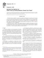
FIG. 1 Overview of DP70 Dropping Point Instrument
3
D127 − 19
or attached, sample cartridges, and accessories. The control with as much wax as possible over the level of the cup in order
unit automatically regulates the heating rate of the furnace. The to minimize the cavity that forms in the center, after the excess
dropping point is indicated on the readout, and the heating wax is cut off.
program stopped, when the sample flow triggers a dropping
point detection. A general view of the contents of the MET- 13.4.2 Fig. 3—The four cups from Fig. 2 have been poured
TLER TOLEDO dropping point instrument is shown in Fig. 1. and cooled. The two cups sitting on top did not get enough
wax. Cavities extend way down in the center of those. The one
13. Procedure on the left had a dropping point of 0.5° lower than the one on
the right. More wax should be poured to begin with, as is
13.1 Secure a sample of sufficient size that is representative evident in the samples in the holder. These will all need
of the material under inspection. Use a fresh portion of the trimming, but they will have a small cavity in the center that
sample for each set of two determinations. Melt the sample does not materially influence the dropping point.
slowly until the temperature reaches at least 11 °C (20 °F)
above the expected drop melting point. The sample should be 13.4.3 Fig. 4—A cup with wax after the drop. Note the
completely melted. The wax should be hot enough that the hanging solidified drop and the pool of wax in the bottom of
wax, when poured, remains transparent enough to see the the receiver glass.
opening in the bottom of the cup when the cup is poured full.
This ensures that no air pockets are trapped in a solidifying 13.4.4 Fig. 5—Two cups in the holder shortly after removal
wax that is not hot enough. (See Note 4.) The cup should be from the DP70, showing the drops and wax in the bottom of the
poured full to the top plus 1 mm to 2 mm above the rim. As the receiver glass.
wax cools in the cup, it cools from the outside in and there is
shrinkage in the center. After cooling, any wax remaining 13.4.5 Fig. 6—The photo from the report with at the
above the top of the cup should be trimmed off with a flat sharp moment of the drop on the right side at 62.2 °C. The sample on
edge. Any wax on the outside of the cup should be cleaned off. the left had already dropped at 61.8 °C. The second drop is
The cup should temper at room temperature (20 °C to 25 °C) about to fall.
for 2 h to allow the wax time to harden. If the wax is too hot
when poured, there will be more shrinkage as it cools, and this 14. Report
will cause a cavity down in the center. Pouring more wax in
after it hardens is not recommended because an air pocket can 14.1 Report both determinations and the average of the two
be trapped in the cavity. A small cavity is almost unavoidable determinations as the drop melting point of the sample under
for some waxes but this should not cause a problem so long as test.
the cup is otherwise full.
14.1.1 The PDF report generated on a USB stick or trans-
NOTE 4—Center cavities are caused by the outside of the cup cooling ferred to an Ethernet connected PC may be examined for
and hardening before the center. This can be minimized by heating the photos of the drop to verify that the drop occurred correctly.
sample preparation tool to near the expected drop temperature before See Fig. 6.
pouring into the dropping point cups. The cooling becomes more uniform
and the cavity less pronounced. 15. Precision and Bias
13.2 Petrolatums should be dropped into ice water after they 15.1 The precision of this test method is based on an
have cooled and gelled so that they retain the shape. The cup interlaboratory study of ASTM D127 – 08 (2014), Standard
should sit in the ice water for at least one hour. Test Method for Drop Melting Point of Petroleum Wax,
Including Petrolatum, conducted in 2014. Eleven laboratories
13.3 The exterior of the cup is cleaned of any wax and tested a total of nineteen different wax samples. Every “test
water, the cap is put on and the glass receptacle fitted to the result” represents an individual determination. All labs were
bottom and held. It is then inserted in the sample holder. asked to report duplicate test results for every material tested.
Usually samples are analyzed in duplicate, as the sample Practice E691 was followed for the design and analysis of the
holder holds two cups. The start temperature should be at least data; the details are given in ASTM Research Report No.
15° below the expected drop temperature, with a 120 s wait RR:D02-1921.4
time before the temperature ramp of 1 °C ⁄minute is started.
When both cups have dropped, the temperature should return 15.1.1 Repeatability Limit (r)—Two test results obtained
to the insert temperature and the results presented on the within one laboratory shall be judged not equivalent if they
display. The video of the drop can be examined if there is any differ by more than the “r” value for that material; “r” is the
doubt about the drop result, and the report can be viewed to see interval representing the critical difference between two test
a photo of the drop at the moment it fell. results for the same material, obtained by the same operator
using the same equipment on the same day in the same
13.4 Illustrations: laboratory.
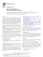
13.4.1 Fig. 2—The dropping point cups have been recently
poured. The lower and right cups have been cooling for several 15.1.1.1 Repeatability limits are listed in Table 3.
minutes. The top cup was just poured. The bottom can be seen 15.1.2 Reproducibility Limit (R)—Two test results shall be
through the transparent molten wax, ensuring that there are no judged not equivalent if they differ by more than the “R” value
entrapped air pockets. The left cup has not been poured. In the for that material; “R” is the interval representing the critical
right cup, the center is still molten. These cups were poured
4 Supporting data have been filed at ASTM International Headquarters and may
be obtained by requesting Research Report RR:D02-1921. Contact ASTM Customer
Service at
4
D127 − 19
FIG. 2 Four Recently Poured Dropping Point Cups
difference between two test results for the same material, laboratories, on nineteen materials. These nineteen materials
obtained by different operators using different equipment in were identified generically in the tables above. ÷DSC analysis
different laboratories. showed in general that waxes with a narrow melting range had
a consistent dropping point with small variation. Waxes with a
15.1.2.1 Reproducibility limits are listed in Tables 1-3. broad melting range, such as the plant wax blends, showed
15.1.3 The above terms (repeatability limit and reproduc- much greater variability in the dropping point by both methods
ibility limit) are used as specified in Practice E177. A and B.
15.1.4 Any judgment in accordance with statements 15.1.1
and 15.1.2 would have an approximate 95 % probability of 15.4 To judge the equivalency of two test results, it is
being correct. recommended to choose the material closest in characteristics
to the test material.
15.2 Bias—At the time of the study, there was no accepted
reference material suitable for determining the bias for this test 16. Keywords
method, therefore no statement on bias is being made.
16.1 drop melting point; petrolatum; petroleum wax; wax
15.3 The precision statement was determined through sta-
tistical examination of all reported results, from eleven
5
D127 − 19
FIG. 3 Four Dropping Point Cups after Pouring and Cooling
6
D127 − 19
FIG. 4 Wax Cup After the Drop
FIG. 5 Two Cups in the Holder After Removal from the DP70
7
D127 − 19
FIG. 6 Report Photo at the Moment of the Drop
8
D127 − 19
TABLE 1 Dropping Point (°C) – Averages, Part A
Sample Average Reproducibility Standard Reproducibility Number of Labs Reporting
Deviation
1 Petrolatum 54.32 SR R 8
2 Natural plant wax 71.95 3.16 8.86 8
3 Paraffin wax 64.80 1.13 3.17 8
4 Microcrystalline wax 89.32 0.41 1.15 8
5 Natural plant wax 96.02 0.75 2.10 8
6 Paraffin wax 69.57 2.14 6.00 8
7 Praffin wax 68.85 0.58 1.64 8
8 Natural wax, beeswax 59.98 0.48 1.35 8
9 Paraffin wax 53.34 0.66 1.85 8
10 Scale wax 53.66 0.78 2.18 8
11 Natural plant wax blend 71.83 5.93 16.60 9
12 Natural plant wax blend 82.23 8.24 23.07 8
13 Polyethylene wax 111.95 7.16 20.06 3
14 Microcrystalline wax 84.70 2.21 6.19 8
15 Paraffin wax 55.95 0.76 2.13 8
16 Petrolatum 61.26 0.43 1.20 8
17 Petrolatum 59.76 1.34 3.74 8
18 Microcrystalline wax 76.82 2.35 6.58 8
19 Microcrystalline wax 81.54 7.28 20.39 8
4.23 11.84
Sample Number of Labs Reporting
TABLE 2 Dropping Point (°C) – Averages, Part B
1 Petrolatum 11
2 Natural plant wax Average Reproducibility Standard Reproducibility 10
3 Paraffin wax Deviation 11
4 Microcrystalline wax 49.72 SR R 11
5 Natural plant wax 73.54 1.91 5.35 10
6 Paraffin wax 65.15 0.90 2.52 11
7 Paraffin wax 90.35 0.87 2.43 11
8 Natural wax, beeswax 97.26 0.56 1.56 11
9 Paraffin wax 70.85 1.14 3.20 11
10 Scale wax 69.98 1.03 2.88 11
11 Blend plant wax 60.18 0.81 2.27 11
12 Blend plant wax 53.56 0.75 2.09 10
13 Polyethylene wax 51.81 0.75 2.11 9
14 Microcrystalline wax 71.56 2.00 5.61 11
15 Paraffin wax 75.99 4.07 11.38 11
16 Petrolatum 113.59 5.86 16.41 11
17 Petrolatum 84.62 0.48 1.35 11
18 Microcrystalline wax 56.13 0.72 2.02 11
19 Microcrystalline wax 58.82 1.01 2.82 11
57.17 2.22 6.23
80.56 1.05 2.93
80.57 1.04 2.91
4.08 11.42
9
D127 − 19
TABLE 3 Dropping Point (°C) – Individual Determinations, Part B
Sample Average Repeatability Reproducibility Repeatability Reproducibility Number of Labs
Standard Deviation Standard Deviation Reporting
1 Petrolatum 49.7 r R
2 Natural plant wax 73.5 Sr SR 0.8 5.4 11
3 Paraffin wax 65.1 0.3 1.9 0.9 2.6 10
4 Microcrystalline wax 90.3 0.3 0.9 1.2 2.6 11
5 Natural plant wax 97.3 0.4 0.9 1.8 2.0 11
6 Paraffin wax 70.9 0.6 0.7 3.5 4.0 10
7 Paraffin wax 70.0 1.2 1.4 1.6 3.1 1
8 Natural wax, beeswax 60.2 0.6 1.1 0.6 2.3 11
9 Paraffin wax 53.6 0.2 0.8 0.6 2.1 1
10 Scale wax 51.8 0.2 0.8 1.5 2.4 11
11 Blend plant wax 71.6 0.5 0.8 1.4 5.7 11
12 Blend plant wax 76.0 0.5 2.0 6.2 12.2 11
13 Polyethylene wax 113.6 2.2 4.4 3.1 16.6 10
14 Microcrystalline wax 84.6 1.1 5.9 0.7 1.4 9
15 Paraffin wax 56.1 0.3 0.5 1.2 2.2 1
16 Petrolatum 58.8 0.4 0.8 0.8 2.9 1
17 Petrolatum 57.2 0.3 1.0 0.7 6.2 11
18 Microcrystalline wax 80.6 0.2 2.2 1.0 3.0 11
19 Microcrystalline wax 80.6 0.3 1.1 0.6 2.9 11
0.2 1.0 1.8 11.5 11
0.6 4.1
SUMMARY OF CHANGES
Committee D02.10 has identified the location of selected changes to this standard since the last issue
(D127 – 08 (2015)) that may impact the use of this standard. (Approved Nov. 1, 2019.)
(1) Added subsections 1.1.1 and 1.1.2. (3) Added Test Method B in Sections 10 – 15
(2) Added D3104, D3954, E177, and E691 to 2.1.
ASTM International takes no position respecting the validity of any patent rights asserted in connection with any item mentioned
in this standard. Users of this standard are expressly advised that determination of the validity of any such patent rights, and the risk
of infringement of such rights, are entirely their own responsibility.
This standard is subject to revision at any time by the responsible technical committee and must be reviewed every five years and
if not revised, either reapproved or withdrawn. Your comments are invited either for revision of this standard or for additional standards
and should be addressed to ASTM International Headquarters. Your comments will receive careful consideration at a meeting of the
responsible technical committee, which you may attend. If you feel that your comments have not received a fair hearing you should
make your views known to the ASTM Committee on Standards, at the address shown below.
This standard is copyrighted by ASTM International, 100 Barr Harbor Drive, PO Box C700, West Conshohocken, PA 19428-2959,
United States. Individual reprints (single or multiple copies) of this standard may be obtained by contacting ASTM at the above
address or at 610-832-9585 (phone), 610-832-9555 (fax), or (e-mail); or through the ASTM website
(www.astm.org). Permission rights to photocopy the standard may also be secured from the Copyright Clearance Center, 222
Rosewood Drive, Danvers, MA 01923, Tel: (978) 646-2600; />
10
![Standard Test Method for Compressive Strength of Hydraulic Cement Mortars (Using 2-in. or [50-mm] Cube Specimens)](https://media.store123doc.com/images/document/14/rc/yi/medium_yil1395845738.jpg)