ASTM D176 − 07 (2012) Standard Test Methods for Solid Filling and Treating Compounds Used for Electrical Insulation
Bạn đang xem bản rút gọn của tài liệu. Xem và tải ngay bản đầy đủ của tài liệu tại đây (142.9 KB, 12 trang )
NOTICE: This standard has either been superseded and replaced by a new version or withdrawn.
Contact ASTM International (www.astm.org) for the latest information
Designation: D176 − 07(Reapproved 2012) An American National Standard
Standard Test Methods for
Solid Filling and Treating Compounds Used for Electrical
Insulation1
This standard is issued under the fixed designation D176; the number immediately following the designation indicates the year of
original adoption or, in the case of revision, the year of last revision. A number in parentheses indicates the year of last reapproval. A
superscript epsilon (´) indicates an editorial change since the last revision or reapproval.
1. Scope* priate safety and health practices and determine the applica-
bility of regulatory limitations prior to use. For specific hazard
1.1 These test methods cover physical and electrical tests statements, see 12.1 and 31.5.
for solid filling and treating compounds used for electrical
insulation which are fusible to a liquid without significant NOTE 1—There is no similar or equivalent IEC or ISO standard.
chemical reaction. Compounds that are converted to the solid
state by polymerization, condensation, or other chemical reac- 2. Referenced Documents
tion are not included in these test methods. 2.1 ASTM Standards:2
D5 Test Method for Penetration of Bituminous Materials
1.2 These test methods are designed primarily for asphaltic D6 Test Method for Loss on Heating of Oil and Asphaltic
or bituminous compounds, waxes, and fusible resins, or mix- Compounds
tures thereof, although some of these methods are applicable to D70 Test Method for Density of Semi-Solid Bituminous
semisolid types such as petrolatums. Special methods more Materials (Pycnometer Method)
suitable for hydrocarbon waxes are contained in Test Methods D71 Test Method for Relative Density of Solid Pitch and
D1168. Asphalt (Displacement Method)
D88 Test Method for Saybolt Viscosity
1.3 Provide adequate ventilation when these tests involve D92 Test Method for Flash and Fire Points by Cleveland
heating. Open Cup Tester
D127 Test Method for Drop Melting Point of Petroleum
1.4 The test methods appear in the following sections: Wax, Including Petrolatum
D149 Test Method for Dielectric Breakdown Voltage and
Test Method Sections Dielectric Strength of Solid Electrical Insulating Materials
at Commercial Power Frequencies
Electrical Tests: Constant) 51-54 D150 Test Methods for AC Loss Characteristics and Permit-
A-C Loss Characteristics and Permittivity (Dielectric 42-45 tivity (Dielectric Constant) of Solid Electrical Insulation
Dielectric Strength 46-49 D257 Test Methods for DC Resistance or Conductance of
Volume Resistivity-Temperature Characteristics Insulating Materials
22-41 D937 Test Method for Cone Penetration of Petrolatum
Physical Tests: 9 and 10 D1168 Test Methods for Hydrocarbon Waxes Used for
Coefficient of Expansion or Contraction 11 and 12 Electrical Insulation
Flash and Fire Points 5 and 6 D1711 Terminology Relating to Electrical Insulation
Loss on Heating 15 and 16 E28 Test Methods for Softening Point of Resins Derived
Melting Point 7 and 8 from Naval Stores by Ring-and-Ball Apparatus
Penetration 17-21 E102 Test Method for Saybolt Furol Viscosity of Bituminous
Softening Point 13 and 14 Materials at High Temperatures
Specific Gravity
Viscosity 3. Terminology
1.5 The values stated in SI units are to be regarded as the 3.1 Definitions:
standard. The values given in parentheses are for information
only. 2 For referenced ASTM standards, visit the ASTM website, www.astm.org, or
contact ASTM Customer Service at For Annual Book of ASTM
1.6 This standard does not purport to address all of the Standards volume information, refer to the standard’s Document Summary page on
safety concerns, if any, associated with its use. It is the the ASTM website.
responsibility of the user of this standard to establish appro-
1 These methods of testing are under the jurisdiction of ASTM Committee D09
on Electrical and Electronic Insulating Materials and are the direct responsibility of
Subcommittee D09.01 on Electrical Insulating Varnishes, Powders and Encapsulat-
ing Compounds.
Current edition approved April 1, 2012. Published April 2012. Originally
approved in 1923. Last previous edition approved in 2007 as D176 – 07. DOI:
10.1520/D0176-07R12.
*A Summary of Changes section appears at the end of this standard
Copyright © ASTM International, 100 Barr Harbor Drive, PO Box C700, West Conshohocken, PA 19428-2959. United States
1
D176 − 07 (2012)
3.1.1 dielectric strength, n—the voltage gradient at which dard methods of sampling have been established. When the
dielectric failure of the insulating material occurs under spe- sample is in the form of cakes or ingots, a representative
cific conditions of test. sample is usually secured by breaking or cutting a transverse
section from the middle of the cake or ingot. When the material
3.1.2 For definitions of other terms relating to electrical is shipped in pails or drums, a sample is removed with a clean
insulation see Terminology D1711. knife, hatchet, auger or other cutting tool, discarding the top 50
or 75 mm (2 or 3 in.) of the compound. Melting of the
3.2 Definitions of Terms Specific to This Standard: compound should be avoided unless it can be poured directly
3.2.1 loss on heating, n—of filling or treating compound, the into the testing container. A melting and pouring temperature of
change in weight of a compound when heated under prescribed 50 °C (90 °F) above the softening point is recommended for
conditions at a standard temperature for a specified time. filling testing containers with asphaltic compounds. Take care
not to overheat the compound nor to entrap air.
3.2.2 melting point, n—of filling or treating compound, the
temperature at which the compound becomes sufficiently fluid 4.2 With certain materials that tend to entrap gasses due to
to drop from the thermometer used in making the determina- high viscosity at pouring temperatures, or to froth on heating,
tion under prescribed conditions. it is necessary to degas the material prior to testing in order that
consistent results are secured (unless the particular test in-
3.2.3 penetration, n— of filling or treating compound, the cludes such procedure). If degassing is required, perform by
distance traveled by a standard needle (or cone) as it pierces a heating the material in a vacuum oven. Ensure the temperature
specimen under specified conditions of load, time and tempera- and vacuum are high enough, and the time long enough to
ture. drive off the mechanically entrapped gasses, but not so high to
decompose the material. A temperature 50 °C (90 °F) higher
3.2.4 softening point, n—of filling or treating compound, the than the softening point of the compound, an absolute pressure
temperature at which the central portion of a disk of the of 7 to 21 kPa (1 to 3 psi), and a time of 30 to 45 min are
compound held within a horizontal ring of specified dimen- recommended for asphaltic compounds. Pour the sample into
sions has sagged or flowed downward a distance of 25 mm (1 the testing container.
in.) under the weight of a 10-mm (3⁄8-in.) diameter steel ball as
the sample is heated at a prescribed rate in a water or glycerin
bath.
4. Sampling and Conditioning
4.1 Due to the diverse nature of the compounds and the
various forms and packages commercially available, no stan-
PHYSICAL TESTS
MELTING POINT the compound has no definite melting point, for purposes of
specification, classification, and control of product uniformity.
5. Significance and Use
8. Procedure
5.1 The melting point is useful in selecting a filling or
treating compound that will not flow at the operating tempera- 8.1 Determine the softening point in accordance with Test
ture of the device in which it will be used. It is also essential Method E28.
that it shall not be so high as to injure the insulation at the time
of pouring. This test method is suitable for specification, FLASH AND FIRE POINTS
classification, and for control of product uniformity.
9. Significance and Use
6. Procedure
9.1 The flash and fire points must be high enough so that the
6.1 Determine the melting point of petrolatums, waxes, and possibility of an explosion or fire is at a minimum when the
similar compounds of a relatively sharp melting point by Test compounds are being heated and poured. A flash point at least
Method D127. 35 °C (63 °F) above the pouring temperature is usually
considered necessary for safe operations. An unusually low
NOTE 2—This method should not be used for asphalts and other types flash point for a given compound indicates a mixture or
with a prolonged melting range. contamination with a volatile material. This test method is
useful for purposes of specification, classification, and control
SOFTENING POINT of product uniformity.
7. Significance and Use 10. Procedure
7.1 The softening point is useful in selecting a filling or 10.1 Determine the flash and fire points of all compounds in
treating compound that will not flow at the operating tempera- accordance with Test Method D92.
ture of the device in which it is used. It is also an indication of
the pouring temperature, which should not be so high as to 10.2 In the case of certain compounds containing chlorine,
injure the insulation of a device. This test method is used, when the flash has the potential to be indefinite and no fire point
exists. Report this fact.
2
D176 − 07 (2012)
LOSS ON HEATING PENETRATION
11. Significance and Use 15. Significance and Use
11.1 Loss on heating includes loss of moisture and volatile 15.1 Penetration is an indication of the softness or indent-
constituents less any weight gain due to oxidization. It is useful ability of a compound. Penetration values are used as a basis
for control of product uniformity and as an indication of pot or for classification, specification, and control of product unifor-
tank life if the test is performed at the appropriate temperature. mity.
This test method shall not be used to compare compounds of
different basic chemical compositions. 16. Procedure
12. Procedure 16.1 Determine penetration in accordance with Test Method
D5. This test method is applicable to all compounds except
12.1 Determine the loss on heating of asphaltic and certain very soft materials and petrolatums. Unless specified other-
other types of compounds by Test Method D6. wise, the standard conditions of test are:
NOTE 3—The reproducibility of this test method has the potential to be Weight, g Time, s
poor due to insufficient control of the air circulation over the specimens
and to weight gain from oxidation of some compounds. With certain At 25 °C (77 °F) 100 5
compounds it is desirable to conduct the test at a lower temperature than Time, s
the specified temperature of 163 °C (325 °F). Other standard conditions are:
Warning—When compounds of low flash point and high Weight, g
volatility are tested, the oven shall have low-temperature
heating elements and a safety door latch to relieve pressure in At 0 °C (32 °F) 200 60
case of an explosion.
At 46 °C (115 °F) 50 5
VISCOSITY
16.2 For very soft materials, such as petrolatums, use Test
Method D937.
SPECIFIC GRAVITY
13. Significance and Use 17. Significance and Use
13.1 The Saybolt viscosity is nearly proportional to the 17.1 Specific gravity is useful for indicating product unifor-
kinematic viscosity of filling and treating compounds and mity and for calculating the weight of a given volume of
hence, it is an indication of whether or not the material will material. In some instances it is useful in estimating the amount
flow readily under its own weight at a prescribed temperature. of mineral fillers in a compound. If specific gravity is known at
It is also satisfactory for control of product uniformity and for several temperatures, the coefficient of expansion is calculated.
specification purposes. If the specific gravity of a compound is determined before and
after degassing, it is possible to calculate the volume of
14. Procedure entrapped gasses.
14.1 For waxes, petrolatums, and other low-viscosity-type 17.2 Displacement tests are used to determine the specific
compounds determine the viscosity as Saybolt Universal vis- gravity of both untreated and degassed compounds. Conven-
cosity by Test Method D88. The standard temperatures for tional methods are used for the solid state, and plummet
testing are: 21, 38, 54, or 99 °C (70, 100, 130, or 210 °F). displacement for the liquid state. The values obtained have the
potential to be used to compute the approximate coefficient of
14.2 For asphaltic and other high-viscosity compounds, cubical expansion by Test Method C (see Sections 34-36).
determine the Saybolt Furol viscosity. The standard tempera-
tures for testing Furol viscosity are: 25, 38, 50, 60, 82, and 99 WATER DISPLACEMENT METHODS
°C (77, 100, 122, 140, 180, 210 °F).
18. Procedure
14.3 For higher temperatures, special techniques and ther-
mometers are required. The standard temperatures are 121, 18.1 Determine the specific gravity by Test Method D70 or
149, 177, 204, and 232 °C (250, 300, 350, 400, 450 °F). In Test Method D71.
these cases determine the viscosity by Test Method E102.
PLUMMET DISPLACEMENT METHOD
NOTE 4—For testing waxes and petrolatums, the standard temperature
for comparison purposes is 99 °C (210 °F), and Saybolt Universal 19. Scope
viscosity is used. For estimation of the properties of asphaltic and other
compounds of high viscosity, it is desirable to measure the viscosity at a 19.1 The specific gravity of the material at the desired
number of standard temperatures above the softening point. A curve is temperature is calculated from the weight of the compound
plotted on log-log paper and the temperature at which the Saybolt Furol displaced by a calibrated aluminum plummet.
viscosity is 470 s is determined. This viscosity corresponds approximately
to a kinematic viscosity of 1000 centistokes, and is a viscosity at which the 20. Apparatus
compound is conveniently poured from the container. With potting
compounds, it is also desirable to know the temperature at which the 20.1 Balance—An analytical balance equipped with pan
Saybolt Furol viscosity is 100 s, since this viscosity is low enough for straddle.
production potting operations.
3
D176 − 07 (2012)
20.2 Plummet—An aluminum plummet of suitable shape These test methods are used for determining either true or
weighing 5 to 10 g. effective coefficient of expansion but are not used as referee
test methods.
20.3 Beaker—A 400-mL heat-resistant glass beaker
wrapped with a suitable thermal insulation. 23. Significance and Use
20.4 Thermometer—A thermometer of suitable range. 23.1 Coefficient of expansion is useful in computing the
amount of void space that will remain in a device filled with
20.5 Wire—Two pieces of fine copper wire. compound after the compound has cooled to the ambient
temperature. It also is one indication of the thermal shock
21. Procedure resistance of a compound.
21.1 Calibration of Plummet—Make the following weight 23.2 The effective coefficient of expansion is determined on
determinations of the plummet to the nearest 1 mg as follows: materials that have not been degassed just prior to test. It is
important for many purposes to know the effective coefficient
a 2 b 5 weight of water displacement in grams at 25 °C ~77 °F! (1) of the material as received or after heating to the maximum
temperature of application. Consistent results, however, are
where: only obtained with gas-free compounds.
a = weight in air, g, and TEST METHOD A—USING GLASS FLASK
b = weight suspended in water, g, at 25°C (77°F).
24. Apparatus
21.2 Correct the value of the plummet displacement (Dtp) in
terms of grams of water at 25°C (77°F) to the pouring 24.1 Flask—A glass flask holding approximately 250 mL to
the zero mark, and graduated for 25 mL in 0.1-mL divisions,
temperature, tp, in degrees Celsius, by means of the following the neck of the flask being 10 mm in internal diameter.
equation
24.2 Oil Bath—For heating the sample, a cylindrical oil bath
Dtp 5 0.000076~tp 2 25!~a 2 b!1~a 2 b! (2) approximately 25.4 cm (10-in.) inside diameter and 50 cm (20
in.) in inside depth with a false bottom 2.5 cm (1 in.) from the
NOTE 5—The factor 0.000076 is the coefficient of cubical expansion per bottom and provision for circulating and heating the oil.
degree Celsius. 24.3 Metal Collar—Lead or iron collars for use on the neck
of the flask during test to prevent oil currents of the bath from
21.3 Testing of the Sample—Carefully melt the sample in moving the flask.
the beaker and raise the temperature to approximately 15°C
(27°F) above the desired test temperature. Place the beaker on 25. Calibration
the straddle and suspend the plummet in the compound by the
fine copper wire. (The weight of the wire should be tared.) 25.1 The capacity of the flask at the zero point and several
points on the scale, shall be determined by filling the flask with
21.4 Balance the scales approximately and at the same time distilled water at a known temperature and weighing.
stir the sample slowly, using the thermometer as a stirring rod.
When the sample has cooled to the desired temperature, rapidly 26. Procedure
complete the weighing.
26.1 Maintain the flask under a vacuum of 640 mm (25 in.)
21.5 Calculation of Specific Gravity, tp/25 C—Calculate the Hg at a temperature 50°C (90°F) higher than the softening
specific gravity as follows: point (ring and ball method, as determined in accordance with
Section 8) while filling, and for approximately 30 min after
Sp gr, tp/25 C 5 ~W a 2 Wc!/Dtp (3) filling is completed. Fill flask to within the last millilitre
marked on the neck when held at the maximum test tempera-
where: ture and slowly cooled to room temperature (10 to 12 h).
Before starting the test, examine the flask for the presence of
Wa = weight of plummet in air, g, and cavities or irregular contraction of the compound. Some
Wc = weight of plummet in compound, g. compounds, after cooling below the liquid state, tend to stick to
the sides of the neck of the flask. In such cases, it is necessary
COEFFICIENT OF EXPANSION OR to gradually warm the neck and flow the compound to meet the
CONTRACTION rest, after which the flask shall be placed in the bath for several
hours to ensure temperature equilibrium.
22. Scope
26.2 With the compound satisfactorily placed in the flask at
22.1 The following four test methods are included: the lowest temperature, read the height of the column in the
neck and then slowly heat the bath. Take readings at 5°C (9°F)
22.1.1 Test Methods A and B—Methods A and B for true intervals, holding the bath as constant as possible at each point
coefficient of expansion are intended for use only where the until no more expansion occurs at that point. Repeat the
uniformity of the material under test justifies a high degree of procedure for each point until maximum temperature is
precision. Test Method A is suitable for testing low-viscosity reached.
types such as waxes and petrolatums. Test Method B is suitable
for testing asphalts and high-viscosity materials, also for
opaque materials that give difficulty in reading the glass scale
of Test Method A.
22.1.2 Test Methods C and E—Test Methods C and E are
intended for faster testing where high precision is not justified.
4
D176 − 07 (2012)
26.3 Precautions—During the test, take temperature read- 30. Calibration
ings at top and bottom of the bath to detect any variation. Make
readings of the expansion of the compound at intervals long 30.1 The cell shall be calibrated to determine its volume at
enough to ensure uniform temperature distribution and com- various temperatures as follows:
plete movement of the compound. Until complete liquefaction,
the interval shall be 3 to 4 h; after liquefaction, it is possible to 30.1.1 Weigh the assembled cell to determine its tare
reduce to 30 min. weight.
27. Calculation 30.1.2 Fill the cell with mercury until replacing the cover
causes some to extrude through the capillary tubing. Record
27.1 After securing the readings over the temperature range the weight of the cell and the mercury and note the tempera-
desired, plot a curve from the temperature and expansion ture.
readings from which the coefficient of expansion shall be
calculated, as follows: 30.1.3 Place the cell in the oil bath in an inverted position.
The capillary tubing should extend over the side of the oil bath
E 5 @~V12 V!/~T 1 2 T!V#1C (4) in such a way that the extruded mercury is caught in a beaker.
The oil bath, which is several degrees above room temperature,
where: will cause some of the mercury to be extruded from the
capillary tube. When all expansion has taken place, weigh the
E = coefficient of expansion (1/T) of the compound, mercury collected.
V = original volume occupied by the compound, L,
V1 = volume at higher temperature occupied by the com- 30.1.4 Adjust the oil bath for other test temperatures and
note the amounts of mercury extruded. The weight of the
pound, L, mercury in the cell at any temperature is thus determined, and
T = original temperature, the volume is calculated.
T1 = higher temperature, and
C = coefficient of cubical expansion of the glass container. 31. Procedure
This is taken as three times the linear coefficient of 31.1 While filling the cell, place it in an oil bath and
expansion. maintain at a temperature 50°C (90°F) higher than the soften-
ing point of the compound (ring and ball method, as deter-
27.2 The coefficient of expansion shall be calculated for mined in accordance with Section 8). When the cell has been
three temperature ranges, as follows: filled to within 6 mm (1⁄4 in.) of the cover, place it in a vacuum
oven and maintain at a vacuum of 640 mm (25 in.) Hg and a
27.2.1 From the minimum temperature at which the mea- temperature 50°C (90°F) higher than the softening point of the
surement was made to 10°C (18°F) below the softening point. compound for a period of not less than 30 min nor more than
This is intended to give the average coefficient for the solid 45 min. At the end of this period slowly cool the cell to room
condition. temperature, and remove any irregularities in the surface of the
compound.
27.2.2 From 5°C (9°F) above the softening point to 50°C
(90°F) above the softening point. This is intended to give the 31.2 Screw on the cover and re-weigh the cell and com-
average coefficient for the liquid condition. pound.
27.2.3 From the minimum temperature at which a measure- 31.3 Pour sufficient mercury into the cell so that some is
ment was made to 50°C (90°F) above the softening point. extruded when the cover is screwed down. Then weigh the cell
again.
28. Report
28.1 Report the following information: 31.4 Invert the cell and place in the oil bath, and repeat the
28.2 Type of cell used, copy of the volume-temperature procedure prescribed in 30.1.3 and 30.1.4 for 5 °-C (9 °-F)
intervals.
curve, temperature ranges as defined in 27.2, and
28.3 Coefficient of expansion corresponding to each of the 31.5 Precautions—Only clean, distilled mercury shall be
used. During the test, take temperature readings at top and
three temperature ranges. bottom of the bath to detect any variation. Readings of the
expansion of the compound should be made at time intervals
TEST METHOD B—USING METALLIC CELL long enough to ensure uniform temperature distribution and
complete movement of the compound. Until complete lique-
29. Apparatus faction of the compound the interval should be 3 to 4 h; after
liquefaction, it is possible to reduce to 30 min.
29.1 Metal Cell—A cell made of steel, consisting of four
parts: a cylinder about 64 mm (2.5 in.) in internal diameter Warning—Mercury metal vapor poisoning has long been
having a rigid bottom, a metallic gasket, and a cover to which recognized as a hazard in industry. The maximum exposure
a steel capillary tube is attached. The cell shall have an internal limits are set by the American Conference of Governmental
volume of approximately 250 mL. A metallic cell that has been Industrial Hygienists.3 The concentration of mercury vapor
found suitable is described in Annex A1.
3 American Conference of Governmental Hygienists, Building D-7, 6500 Glen-
29.2 Oil Bath—An oil bath as described in 24.2, Test way Drive, Cincinnati, OH 45211.
Method A, with the exception that provision shall be made for
supporting the metal cell.
5
D176 − 07 (2012)
resulting from use of the above procedure can easily exceed T = initial temperature, and
these exposure limits. Mercury, being a liquid and quite heavy, T1 = higher temperature.
will disintegrate into small droplets and seep into cracks and
crevices in the floor if it is spilled. The increased area of 36. Report
exposure adds significantly to the mercury vapor concentration
in the air. Mercury vapor concentration is easily monitored 36.1 Report the following information: ranges
using commercially available sniffers. Spot checks shall be 36.1.1 Method used,
made periodically around operations where mercury is exposed 36.1.2 Temperature ranges used, and
to the atmosphere. Thorough checks shall be made after spills. 36.1.3 Coefficient of expansion over temperature
Emergency spill kits are available should the airborne concen- used.
tration exceed the exposure limits. In addition, exercise care to
keep the mercury from the hands. The use of rubber gloves is TEST METHOD D PYCNOMETER EXPANSION
recommended for handling specimens in the above manner.
37. Scope
32. Calculation
37.1 This test method is another modification of the specific
32.1 After volumetric determinations have been made over gravity method (Test Method C) and is applied to either
the desired temperature range, plot a curve between volume untreated or degassed materials. This test method is applicable
and temperature readings from which the coefficient of expan- up to temperatures at which the extruded compound flows
sion shall be calculated, as follows: down the side of the flask and cannot be removed with
sufficient precision for weighing.
E 5 ~V1 2 V!/~t 1 2 T!V (5) 38. Apparatus
where: 38.1 Flask and Pycnometer—A 100-mL volumetric heat-
resistant glass flask having the zero mark as near as possible to
E = coefficient of expansion (1/T) of the compound, the bulb of the flask and having the neck of the flask cut off at
V = original volume occupied by the compound, L, the 100-mL point and ground square. A metal pycnometer is an
V1 = volume at higher temperature occupied by the com- alternative, provided its coefficient of expansion is known and
is applied in the calculation (Section 40).
pound, L,
T = original temperature, and 38.2 Oil Bath—One possible oil bath consists of a tall-form
T1 = higher temperature. heat-resistant glass beaker of sufficient size so that when the
flask is supported about 1 in. from the bottom the oil level will
32.2 Calculate the coefficient of expansion for the same reach at least to the zero mark of the flask.
three ranges as prescribed in Test Method A.
38.3 Metal Collar—Lead or iron collars for use on the neck
33. Report of the flask during heating to prevent oil currents of the bath
from moving the flask.
33.1 Report the following information:
33.1.1 Type of cell used, 39. Procedure
33.1.2 Copy of the volume-temperature curve,
33.1.3 Temperature ranges as defined in 27.2, and 39.1 Allow the pycnometer to cool slowly to the lowest test
33.1.4 Coefficient of expansion corresponding to each of the temperature. During the cooling period keep the flask filled by
three temperature ranges. adding more compound, and after equilibrium is reached,
remove the excess material by passing a sharp, flat blade over
TEST METHOD C—SPECIFIC GRAVITY METHOD the rim. Remove the flask from the bath and quickly weigh.
Knowing the tare weight and volume of the flask, it is possible
34. Procedure to determine the specific gravity. For successively higher
temperatures, it is only necessary to weigh the extruded
34.1 Determine the specific gravity of untreated or degassed portion. It is recommended that the extruded compound be cut
compounds at two test temperatures by one or more of the off by tared single-edge razor blades which can be transferred
procedures specified in Sections 17-21 applying to the state of directly to the balance pan. About 11⁄2 h will generally be
the materials at the temperatures between which measurements required to establish temperature equilibrium.
are desired.
40. Calculation
NOTE 6—When the temperature range includes the range over which
the material changes from solid to liquid, a true coefficient of expansion
cannot be calculated, although for practical purposes this is done.
35. Calculation 40.1 From the temperature and weight readings calculate
the coefficient of expansion as follows:
35.1 From the temperature and specific gravity readings,
calculate the coefficient of expansion as follows: E 5 @~W 2 W1!/W1~T1 2 T!# 2 ~WC/W 1! (7)
E 5 sp gr at T 2 sp gr at T1/~T1 2 T! sp gr at T1 (6) where:
where: E = coefficient of expansion (1/T),
E = coefficient of expansion (1/T) of the compound, W = initial weight of the compound in the flask, g,
6
D176 − 07 (2012)
W1 = weight of the compound in the flask at higher tem- 41.1.2 Temperature ranges used, and
perature, g, 41.1.3 Coefficient of expansion over temperature ranges
used.
T = initial temperature,
T1 = higher temperature, and
C = coefficient of cubical expansion of the flask.
41. Report
41.1 Report the following information:
41.1.1 Method used,
ELECTRICAL TESTS
DIELECTRIC STRENGTH VOLUME RESISTIVITY-TEMPERATURE
CHARACTERISTICS
42. Significance and Use
46. Significance and Use
42.1 Dielectric strength is of importance as a measure of the
ability of a compound to withstand electrical stress. It serves to 46.1 The volume resistivity of a compound is a measure of
indicate the presence of contaminating materials, such as its electrical insulating properties under conditions comparable
water, dirt, or conducting particles. It is of value for purposes to those pertaining during the test. High resistivity reflects low
of comparison or as an indication of the condition of a content of free ions and ion-forming particles, and normally
compound, but it is not a direct measure of the dielectric indicates a low concentration of conductive contaminants.
strength of a compound when subjected to electric stresses in
service. 46.2 The volume resistivity of compounds varies with the
temperature, generally decreasing rapidly with increase of
NOTE 7—Should the maximum voltage of the testing equipment be temperature. A sufficient number of tests should be made at
insufficient to produce breakdown under the specified conditions of test, it different temperatures to establish the volume resistivity-
is possible to set the gap to 1.3 mm (0.05 in.) The dielectric strength with temperature curve. The curve should include tests up to the
the reduced gap will not be directly comparable with the values deter- highest service temperatures. At room temperature and below,
mined with the standard gap, and must always be accompanied by a the volume resistivity of practically all compounds is so high
statement of the gap length. that it cannot be measured conveniently. The volume resistivity
at a specific temperature is useful to detect contamination of
43. Test Specimens and Electrodes the compound in manufacture or use.
43.1 The compound shall be tested between polished hemi- 47. Test Specimens and Electrodes
spherical electrodes 13 mm (1⁄2 in.) in diameter separated by a
gap of 2.54 mm (0.100 in.). 47.1 A suitable test cell consisting of parallel planes, con-
centric cylinders, or coaxial cones shall be used in determining
NOTE 8—A form of apparatus for holding the electrodes and compound the volume resistivity of the compound (see Test Methods
is described in Annex A2. D257). This distance between electrodes shall be not less than
0.75 mm (0.03 in.) nor more than 5 mm (0.2 in.). The area of
44. Procedure the electrode shall be sufficiently large so that the current can
be measured, with the apparatus available, to an accuracy
44.1 Take a representative sample of the material from the within 5 %. Electrode areas of 50 to 500 cm2 (8 to 78 in.2)
original package, melt, and pour directly into the testing should prove suitable. Because of possible catalytic or corro-
container, taking care not to overheat the compound nor to sive effects of some compounds on certain metals, the elec-
entrap air in it. A melting and pouring temperature of approxi- trodes should be brass-plated nickel, gold, or platinum. The
mately 50 °C (90 °F) above the softening point is recom- insulating material used to support the electrodes shall be
mended for asphaltic compounds. Thoroughly dry the paper- capable of withstanding the wide temperature range to which
board test receptacles by heating before using. the cell is subjected, and preferably shall be of an inorganic
material such as a ceramic material or suitable glass. A test cell
44.2 Determine the short-time dielectric strength in accor- that has been found suitable is described in Annex A3.
dance with Test Method D149. Test five specimens at 25 6 5
°C and take the average value of the voltage gradient as the 48. Procedure
short-time dielectric strength of the compound at that tempera-
ture. Apply voltage to the test specimens at a uniform rate of 48.1 Measure the volume resistivity at each temperature in
increase of 1000 V/s, from zero to breakdown. accordance with Test Methods D257. Test at 500 volts. The
voltage gradient shall not be greater than 1200 V/mm (30
45. Report V/mil). Take readings at each test temperature at an electrifi-
cation time of 1 min. Make a test run with the empty cell over
45.1 The report shall be in accordance with Test Method the desired temperature range. If the measured resistance is 100
D149.
7
D176 − 07 (2012)
or more times that obtained subsequently with the filled cell, 50.2 The loss index is a measure of the energy loss in a
any error introduced by the cell will be less than 1 % and compound when it is subjected to an alternating electric field.
inconsequential.
50.3 When compounds have approximately the same per-
48.2 Take a representative sample from the original pack- mittivity the dissipation factor is useful for comparison of the
age, melt, and pour directly into the test cell, taking care not to relative power loss. Permittivity and dissipation factor are
overheat the compound nor to entrap air in it. A melting and useful in the control of product uniformity. When the com-
pouring temperature of approximately 50 °C (90 °F) above the pound is used to surround conductors, the loss index should
softening point is recommended for asphalts. The quantity of generally be as low as possible, but when it is used in capacitor
the sample depends upon the capacity of the test cell used, but manufacture a high permittivity and a low dissipation factor are
in any case it shall be sufficient to permit three separate desirable.
determinations. Before filling, heat the test cell to slightly
above the pouring temperature of the compound. A suggested 50.4 The dielectric properties of solid filling and treating
procedure in filling the cell, especially in the case of the higher compounds vary with the temperature and frequency of the
melting compounds, is to determine the quantity of compound test. Compounds should be tested at the operating frequency
necessary just to fill the cell with the electrodes in position. In and over a range of temperatures representative of service
the case of coaxial cones or concentric cylinders, first pour the conditions. Some materials display maxima or minima in a
proper quantity of the heated compound slowly into the outer curve of dielectric properties against temperatures. A sufficient
cone or cylinder. Remove any bubbles which form on the number of test temperatures must be used to portray accurately
surface of the compound by a quick application of a flame from the functional relation.
a bunsen burner. Immediately lower the inner electrode into the
compound and place a thermometer in the well. 51. Test Specimens and Electrodes
48.3 Place the test cell, after filling, in an oil or air bath 51.1 For materials tested at low frequencies the same cell
having suitable temperature, control, and allow sufficient time used for resistivity tests is applicable and convenient. For
to bring the bath and cell to temperature equilibrium at each materials tested at high frequencies and over a temperature
test temperature. Determine the temperature of the cell by two range in which they are always in the solid state, it is preferable
mercury thermometers placed in contact with the electrodes. to cast or press a disk or square of the material. Foil electrodes
Determine the temperature of the bath by a mercury thermom- are then applied to the specimen as described for solid
eter placed near the cell. The temperature of the bath shall be specimens in Test Methods D150. See Annex A3.
within 1 °C (2 °F) of the sample temperature when readings are
taken. Take the temperature of the compound as the average of 51.2 For measurements at frequencies up to 1 MHz, the test
the readings of the thermometers measuring the temperatures cell shall have a capacitance of not less than 100 pF when filled
of the inner and outer electrodes when concentric cylinders are with the material under test.
used. The temperatures of the cell thermometers shall agree
within 0.5 °C (1 °F). In the case of parallel-plane electrodes, 52. Procedure
when heat can flow to the compound from both sides, an
average of the electrode temperatures does not give the true 52.1 Determine the permittivity dissipation factor, and loss
compound temperature unless the electrode temperatures have index in accordance with Test Methods D150, selecting suit-
been constant for a period. Fifteen minutes will be sufficient for able apparatus for the frequency range of the measurement.
a 5-mm layer of most compounds to assume equilibrium when
the electrode temperatures differ by 0.5 °C (1 °F) or less. 52.2 Take a representative sample from the original pack-
age, heat to a temperature approximately 50 °C (90 °F) above
49. Report the softening point, and pour it into the preheated cell or mold.
A sufficient quantity of sample shall be taken to permit making
49.1 Report the following information: at least three determinations.
49.1.1 Type of test cell used,
49.1.2 Distance between guarded and unguarded electrodes, 52.3 The voltage gradient shall not exceed 1200 V/mm (30
49.1.3 Area of the guarded electrode, V/mil). Provide an air or oil bath for the test cell or an air bath
49.1.4 Applied voltage and time of electrification, and for the cast test specimen. Determine the temperatures of the
49.1.5 These values are plotted as the logarithm of resistiv- inner and outer electrodes in the case of the cell, or of the upper
ity as a function of the reciprocal of temperature. and lower electrodes in the case of the cast specimen, by
thermometers or thermocouples. When using the cell, assume
A-C LOSS CHARACTERISTICS AND the specimen temperature to be the average of the two
PERMITTIVITY (DIELECTRIC CONSTANT) electrode temperatures when they agree within 0.5 °C (1 °F)
and are substantially constant during a 5-min period, or
50. Significance and Use alternatively during the readings. In the case of parallel plane
electrodes when heat can flow to the compound from both
50.1 The permittivity of a compound indicates the increase sides, an average of the electrode temperatures does not give
in capacitance to be expected when a device is filled with the the true compound temperature unless the electrode tempera-
compound. tures have been constant for a period. Fifteen minutes will be
sufficient for a 5-mm layer of most compounds to assume
equilibrium when the electrode temperatures differ by 0.5 °C (1
°F) or less.
8
D176 − 07 (2012)
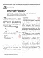
53. Report 55. Keywords
53.1 Report the following information: 55.1 AC loss characteristics; asphaltic compounds; bitumi-
53.1.1 Type of cell or cast specimen used and the pertinent nous compounds; coefficient of expansion or contraction;
dimensions, dielectric strength; fire point; flash point; fusible resins; loss on
53.1.2 Method and type of apparatus used and the frequency heating; melting point; penetration; permittivity (dielectric
at which the measurements were made, constant); softening point; solid filling compounds; solid treat-
53.1.3 Voltage applied to the specimen during test, and ing compounds; specific gravity; viscosity; volume resistivity-
53.1.4 Permittivity dissipation factor and loss index of the temperature characteristics; waxes
specimen at each test temperature.
54. Precision and Bias
54.1 The precision and bias of the methods included herein
are not known due to the age of these test methods and the lack
of current data.
ANNEXES
(Mandatory Information)
A1. CELL FOR DETERMINING COEFFICIENT OF EXPANSION
A1.1 Fig. A1.1 shows the metallic cell for coefficient of FIG. A1.1 Metallic Cell for Coefficient of Expansion Determina-
expansion determinations of solid filling and treating com- tions
pounds. The cell consists of four principal parts: a steel
cylinder, a metallic gasket, a steel cover, and a dummy or
auxiliary cover for filling. The gasket must be of a metal which
does not amalgamate with mercury.
A1.2 The cylinder is about 64 mm (2.5 in.) in internal
diameter, and approximately 76 mm (3 in.) in internal depth.
The top of the cylinder is threaded to receive the steel cover
and has a machined shoulder to seat a 0.076 mm (0.003 in.)
thick metallic gasket. The cylinder is one-piece construction or
fitted with a cap at the bottom similar to the top end.
A1.3 The steel cover is carefully rounded on the under side
to avoid air pockets. It is threaded into the top of the cylinder
and seats on the metallic gasket. The center of the cover is
threaded to receive a steel capillary tube of 0.46 mm (0.018 in.)
in internal diameter.
9
D176 − 07 (2012)
A2. DEVICE FOR DETERMINING DIELECTRIC STRENGTH
A2.1 Because of the great difficulty in removing most solid FIG. A2.1 Container for Dielectric Strength Test Showing Elec-
filling and treating compounds from the container, it is desir- trodes in Place
able to use a test assembly having an inexpensive container
which can be thrown away after a test. A device of this sort is
illustrated in Fig. A2.1.
A2.2 The test assembly consists of a framework made from
suitable plastic laminate, large enough to hold loosely a box of
heavy paper of 2.5 by 3.2 by 4.5-cm (1 by 1 1⁄4 by 1 3⁄4-in.)
inside dimensions, with brass bushings centrally inserted in
each end piece to hold the electrode rods. The electrodes,
which are separable by means of screw joints, are inserted
through small holes in the ends of the paper box and clamped
to make a compound-tight joint. For the electrodes, a metal is
selected that will give minimum gap changes with temperature.
Steel has been found quite satisfactory. The proper electrode
spacing is obtained by means of an adjusting screw on the
right-hand end.
A2.3 After use, the electrode-supporting screws are backed
off; the paper-based container, holding part of the electrodes, is
then easily withdrawn. The electrode parts are salvaged by
melting the compound, and discarding the used paperboard
container.
10
D176 − 07 (2012)
A3. MEASURING CELL FOR RESISTIVITY, DISSIPATION FACTOR, AND PERMITTIVITY MEASUREMENTS
A3.1 A conductivity cell that has been developed for the A3.1.1 Ease of insulating electrodes.
purpose of measuring the volume resistivity as well as other
electrical constants of solid filling and treating compounds is A3.1.2 Large area of electrodes in compact form, the outer
shown in Fig. A3.1 The concentric cylinder type of cell was one of which also serves as container for the compound. This
chosen after experimenting with various types for the follow- outer electrode is also exposed directly to the heating medium
ing points of simplicity and efficiency: and aids in rapid changes from one temperature to another and
also promotes uniform temperature distribution in the com-
FIG. A3.1 Measuring Cell for Resistivity, Dissipation Factor, and paratively thin layer of compound in contact with it.
Dielectric Constant Determinations
A3.1.3 Comparative ease in assembling, disassembling, and
cleaning the cell.
A3.2 This type of cell permits the use of a very small
amount of insulating material to insulate the electrodes. Glass-
bonded mica has been found to be a satisfactory material for
this purpose, due to the fact that it can be machined to size and
has good insulation-resistance characteristics over the tempera-
ture range at which these compounds are normally tested. Also,
it apparently is unaffected by the solvents used in the cleaning
operation.
A3.3 A suggested method of cleaning the cell is to remove
the bottom retaining ring and to hang the cell in an oven by a
hook fastened through a hole drilled in the protruding stem.
Upon heating, the outer cylinder will slide away from the inner
electrode and both parts will drain fairly clean of the com-
pound. In order to speed up this cleaning, the flame of a Bunsen
burner is applied directly to the cell after removing the cap and
suspending the cell by the protruding stem. Further application
of the flame to the cylinder and inner electrode after they
separate will rapidly remove most of the compound, and the
final cleaning of each part can be accomplished by suitable
solvents.
SUMMARY OF CHANGES
Committee D09 has identified the location of selected changes to these test methods since the last issue,
D176 – 00, that may impact the use of these test methods. (Approved May 1, 2007)
(1) This standard was revised throughout to enhance clarity and
readability.
11
D176 − 07 (2012)
ASTM International takes no position respecting the validity of any patent rights asserted in connection with any item mentioned
in this standard. Users of this standard are expressly advised that determination of the validity of any such patent rights, and the risk
of infringement of such rights, are entirely their own responsibility.
This standard is subject to revision at any time by the responsible technical committee and must be reviewed every five years and
if not revised, either reapproved or withdrawn. Your comments are invited either for revision of this standard or for additional standards
and should be addressed to ASTM International Headquarters. Your comments will receive careful consideration at a meeting of the
responsible technical committee, which you may attend. If you feel that your comments have not received a fair hearing you should
make your views known to the ASTM Committee on Standards, at the address shown below.
This standard is copyrighted by ASTM International, 100 Barr Harbor Drive, PO Box C700, West Conshohocken, PA 19428-2959,
United States. Individual reprints (single or multiple copies) of this standard may be obtained by contacting ASTM at the above
address or at 610-832-9585 (phone), 610-832-9555 (fax), or (e-mail); or through the ASTM website
(www.astm.org). Permission rights to photocopy the standard may also be secured from the ASTM website (www.astm.org/
COPYRIGHT/).
12