ASTM D229 19e1 Standard Test Methods for Rigid Sheet and Plate Materials Used for Electrical Insulation
Bạn đang xem bản rút gọn của tài liệu. Xem và tải ngay bản đầy đủ của tài liệu tại đây (527.3 KB, 18 trang )
This international standard was developed in accordance with internationally recognized principles on standardization established in the Decision on Principles for the
Development of International Standards, Guides and Recommendations issued by the World Trade Organization Technical Barriers to Trade (TBT) Committee.
Designation: D229 − 19´1
Standard Test Methods for
Rigid Sheet and Plate Materials Used for Electrical
Insulation1
This standard is issued under the fixed designation D229; the number immediately following the designation indicates the year of
original adoption or, in the case of revision, the year of last revision. A number in parentheses indicates the year of last reapproval. A
superscript epsilon (´) indicates an editorial change since the last revision or reapproval.
ε1 NOTE—The title of Table 1 was editorially corrected in August 2019.
This standard has been approved for use by agencies of the U.S. Department of Defense.
1. Scope* conversions to SI units that are provided for information only
and are not considered standard.
1.1 These test methods cover procedures for testing rigid
electrical insulation normally manufactured in flat sheet or 1.6 This is a fire-test-response standard. See Sections 61
plate form. They are generally used as terminal boards, spacers, through 74, which are the procedures for assessing ignitability
voltage barriers, and circuit boards. and burning time under specific test conditions
1.2 Use Test Methods D619 (withdrawn) or Specification 1.7 This standard does not purport to address all of the
D710 for tests applying to vulcanized fibre. safety concerns, if any, associated with its use. It is the
responsibility of the user of this standard to establish appro-
1.3 Some of the test methods contained in this standard are priate safety, health, and environmental practices and deter-
similar to those contained in IEC 60893-2, which applies to mine the applicability of regulatory limitations prior to use.
rigid industrial laminated sheets based on thermosetting resins Specific precautionary statements are given in 31.1 and 1.8.
for electrical purposes.
1.8 This standard measures and describes the response of
1.4 The test methods appear in the following sections: materials, products, or assemblies to heat and flame under
controlled conditions, but does not by itself incorporate all
Test Sections ASTM factors required for fire hazard or fire risk assessment of the
Acetone extractable matter 82 to 83 Test materials, products, or assemblies under actual fire conditions.
Arc resistance
Ash 47 Method 1.9 Fire testing is inherently hazardous. Adequate safe-
Bonding strength 56 to 60 D494 guards for personnel and property shall be employed in
Flammability methods I and II 49 to 54 D495 conducting these tests.
Coefficient of linear thermal expansion 61 to 74 ...
Compressive strength ... 1.10 This international standard was developed in accor-
Conditioning 76 ... dance with internationally recognized principles on standard-
Dissipation factor 25 D696 ization established in the Decision on Principles for the
Dielectric strength D695 Development of International Standards, Guides and Recom-
Expansion (linear thermal) 4 D6054 mendations issued by the World Trade Organization Technical
Flexural properties 34 to 40 D669 Barriers to Trade (TBT) Committee.
Hardness (Rockwell) 28 to 33 D149
Insulation resistance and resistivity D696 2. Referenced Documents
Permittivity 75 D790 2.1 ASTM Standards:2
Resistance to impact 12 to 24 D785 D149 Test Method for Dielectric Breakdown Voltage and
Tensile properties D257 Dielectric Strength of Solid Electrical Insulating Materials
Thickness 55 D150 at Commercial Power Frequencies
Tracking resistance 41 to 46 D256 D150 Test Methods for AC Loss Characteristics and Permit-
Warp or twist 34 to 40 D638 tivity (Dielectric Constant) of Solid Electrical Insulation
Water absorption D374
26 D2132 2 For referenced ASTM standards, visit the ASTM website, www.astm.org, or
7 to 11 ... contact ASTM Customer Service at For Annual Book of ASTM
5 to 6 D570 Standards volume information, refer to the standard’s Document Summary page on
the ASTM website.
48
76 to 81
27
1.5 The values stated in inch-pound units are to be regarded
as standard. The values given in parentheses are mathematical
1 These test methods are under the jurisdiction of ASTM Committee D09 on
Electrical and Electronic Insulating Materials and are the direct responsibility of
Subcommittee D09.07 on Electrical Insulating Materials.
Current edition approved March 1, 2019. Published March 2019. Originally
approved in 1925. Last previous edition approved in 2013 as D229 – 13. DOI:
10.1520/D0229-19E01.
*A Summary of Changes section appears at the end of this standard
Copyright © ASTM International, 100 Barr Harbor Drive, PO Box C700, West Conshohocken, PA 19428-2959. United States
1
D229 − 19´1
D256 Test Methods for Determining the Izod Pendulum 2.2 IEC Standard:
Impact Resistance of Plastics IEC 60893–2 Specification for Rigid Industrial Laminated
D257 Test Methods for DC Resistance or Conductance of Sheets Based on Thermosetting Resins for Electrical
Insulating Materials Purpose, Methods of Tests4
2.3 International Organization for Standardization (ISO)
D374 Test Methods for Thickness of Solid Electrical Insu- Standard:
lation (Metric) D0374_D0374M ISO 13943 Fire Safety: Vocabulary5
D494 Test Method for Acetone Extraction of Phenolic 3. Terminology
Molded or Laminated Products
3.1 Definitions—Rigid electrical insulating materials are
D495 Test Method for High-Voltage, Low-Current, Dry Arc defined in these test methods in accordance with Terminology
Resistance of Solid Electrical Insulation D883. The terminology applied to materials in these test
methods shall be in accordance with the terms appearing in
D570 Test Method for Water Absorption of Plastics Terminologies D883 and D1711. Use Terminology E176 and
D617 Test Method for Punching Quality of Phenolic Lami- ISO 13943 for definitions of terms used in this test method and
associated with fire issues. Where differences exist in
nated Sheets (Withdrawn 2003)3 definitions, those contained in Terminology E176 shall be used.
D619 Test Methods for Vulcanized Fibre Used for Electrical
3.2 Definitions of Terms Specific to This Standard:
Insulation 3.2.1 In referring to the cutting, application, and loading of
D638 Test Method for Tensile Properties of Plastics the specimens, the following terms apply:
D669 Test Method for Dissipation Factor and Permittivity 3.2.1.1 crosswise (CW), adj—in the direction of the sheet at
90° to the lengthwise direction.
Parallel with Laminations of Laminated Sheet and Plate 3.2.1.1.1 Discussion—This is normally the weakest direc-
Materials (Withdrawn 2012)3 tion in flexure. For some materials, including the raw materials
D695 Test Method for Compressive Properties of Rigid used for manufacture of materials considered herein, this
Plastics direction may be designated as the cross-machine direction or
D696 Test Method for Coefficient of Linear Thermal Expan- the weft direction.
sion of Plastics Between −30°C and 30°C with a Vitreous 3.2.1.2 edgewise loading, n—mechanical force applied in
Silica Dilatometer the plane of the original sheet or plate.
D710 Specification for Vulcanized Fibre Sheets, Rods, and 3.2.1.3 flatwise loading, n—mechanical force applied nor-
Tubes Used for Electrical Insulation mal to the surfaces of the original sheet or plate.
D785 Test Method for Rockwell Hardness of Plastics and 3.2.1.4 lengthwise (LW), adj—in the direction of the sheet
Electrical Insulating Materials which is strongest in flexure.
D790 Test Methods for Flexural Properties of Unreinforced 3.2.1.4.1 Discussion—For some materials, including the
and Reinforced Plastics and Electrical Insulating Materi- raw materials used for the manufacture of materials considered
als herein, this direction may be designated as the machine
D792 Test Methods for Density and Specific Gravity (Rela- direction or the warp direction.
tive Density) of Plastics by Displacement 3.2.2 In referring to bonding strength, the following term
D883 Terminology Relating to Plastics applies:
D1674 Test Method for Testing Polymerizable Embedding 3.2.2.1 bonding strength, n—the force required to split a
Compounds Used for Electrical Insulation (Withdrawn prescribed specimen under the test conditions specified herein.
1990)3 3.2.3 In reference to ignitability and burning time, the
D1711 Terminology Relating to Electrical Insulation following terms apply:
D1825 Practice for Etching and Cleaning Copper-Clad Elec- 3.2.3.1 ignition time, n—the elapsed time in seconds re-
trical Insulating Materials and Thermosetting Laminates quired to produce ignition under conditions of this test method.
for Electrical Testing (Withdrawn 2012)3 3.2.3.2 burning time, n—the elapsed time that the specimen
D2132 Test Method for Dust-and-Fog Tracking and Erosion burns after removal of the ignition heat source under conditions
Resistance of Electrical Insulating Materials of this test method.
D2303 Test Methods for Liquid-Contaminant, Inclined-
Plane Tracking and Erosion of Insulating Materials 4. Conditioning
D3487 Specification for Mineral Insulating Oil Used in
Electrical Apparatus 4.1 The properties of the materials described in these test
D5032 Practice for Maintaining Constant Relative Humidity methods are affected by the temperature and moisture exposure
by Means of Aqueous Glycerin Solutions
D6054 Practice for Conditioning Electrical Insulating Mate- 4 Available from American National Standards Institute (ANSI), 25 W. 43rd St.,
rials for Testing (Withdrawn 2012)3 4th Floor, New York, NY 10036, .
E176 Terminology of Fire Standards
E197 Specification for Enclosures and Servicing Units for 5 Available from International Organization for Standardization, P.O. Box 56,
Tests Above and Below Room Temperature (Withdrawn CH-1211, Geneva 20, Switzerland or from American National Standards Institute
1981)3 (ANSI), 25 W. 43rd St., 4th Floor, New York, NY 10036, .
3 The last approved version of this historical standard is referenced on
www.astm.org.
2
D229 − 19´1
of the materials to a greater or lesser extent, depending on the devices, indicate that the trade is able to measure sheets 1⁄32 and
particular material and the specific property. Control of tem- 1⁄8 in. (1 and 3 mm) in thickness to accuracy of 0.0015 in.
perature and humidity exposure is undertaken to: (1) obtain (0.0381 mm). (In the tests, σ, of 0.0005 in. (0.0127 mm) was
satisfactory test precision, or (2) study the behavior of the obtained.)
material as influenced by specific temperature and humidity
conditions. 6.2 This test method has no bias because the value for
breaking strength is determined solely in terms of this test
4.2 Unless otherwise specified in these test methods or by a method itself.
specific ASTM material specification, or unless material be-
havior at a specific exposure is desired, condition test speci- TENSILE PROPERTIES
mens in accordance with Procedure A of Practice D6054 and
test in the Standard Laboratory Atmosphere (23 6 1.1°C, 50 6 7. Test Specimens
2 % relative humidity).
7.1 Machine the test specimens from sample material to
THICKNESS conform to the dimensions of sheet and plate materials in Fig.
1.
5. Apparatus and Procedure
7.2 Prepare four LW and four CW specimens.
5.1 Measure thickness in accordance with Test Methods
D374. 8. Rate of Loading
5.2 On test specimens, the use of a machinist’s micrometer 8.1 The materials covered by these test methods generally
as specified in Method B is satisfactory for the determination of exhibit high elastic modulus. Use any crosshead speed pro-
thickness for all of the test methods that follow. Where it is vided that the load and strain indicators are capable of accurate
convenient, use the deadweight dial micrometer, Method C. measurement at the speed used, except use 0.05 in./min (1
mm/min) in matters of dispute.
5.3 On large sheets, use Method B. Choose a micrometer
with a yoke of sufficient size and rigidity to permit accurate 9. Procedure
measurements in the center of the sheet.
9.1 Measure the tensile strength and elastic modulus in
6. Precision and Bias accordance with Test Method D638 except as modified in the
following paragraphs.
6.1 Results of comparative tests in several factories, mea-
suring 36-in. (914-mm) square sheets by a variety of such 9.2 Measure the width and thickness of the specimen to the
nearest 0.001 in. (0.025 mm) at several points along the length
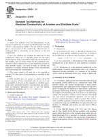
Nominal Thickness, T
Dimension 1⁄4 in. (6 mm) or Under Over 1⁄4 in. (6 mm) to 1⁄2 in. Over 1⁄2 in. (13 mm) to 1 Tolerance
(13 mm), incl in. (25 mm), inclA
Type I Type IIB Type I Type IIB Type I
mm in. mm in. mm in. mm in. mm in. mm in.
C—Width over-all 19.05 0.750 19.05 0.750 28.57 1.125 28.57 1.125 38.10 1.500 ±0.40 + 0.016
−0.00 −0.000
W—Width of flat section 12.70 0.500 6.35 0.250 19.05 0.750 9.52 0.375 25.40 1.000 + 0.12 + 0.005
F—Length of flat section 57.1 2.25 57.1 2.250 57.1 2.25 57.1 2.25 57.1 2.25 ±0.40 ±0.016
G—Gauge lengthC 50.8 2.00 50.8 2.00 50.8 2.00 50.8 2.00 50.8 2.00 ±0.40 ±0.016
D—Distance between grips 114 41⁄2 133 51⁄4 114 41⁄2 133 51⁄4 133 51⁄4 ±3 ±1⁄8
L—Length over-all 216 81⁄2 238 93⁄8 248 93⁄4 257 101⁄8 305 12 min min
Rad.—Radius of fillet 76 3 76 3 76 3 76 3 76 3 min min
A For sheets of a nominal thickness over 1 in. (25.4 mm) machine the specimens to 1 in. (25.4 mm) ± 0.010 in. (0.25 mm) in thickness. For thickness between 1 in. (25.4
mm) and 2 in. (51 mm), machine approximately equal amounts from each surface. For thicker sheets, machine both surfaces and note the location of the specimen with
reference to the original thickness.
B Use the type II specimen for material from which the Type I specimen does not give satisfactory failures in the gauge length, such as for resin-impregnated compressed
laminated wood.
C Test marks only.
FIG. 1 Tension Test Specimen for Sheet and Plate Insulating Materials
3
D229 − 19´1
of the flat section, which is indicated as Dimension F in Fig. 1. 13. Rate of Loading
Record the minimum values of cross-sectional area so deter-
mined. 13.1 The materials covered by these test methods generally
rupture during flexural testing at small deflections. Therefore,
9.3 Place the specimen in the grips of the testing machine, Procedure A (strain rate of 0.01/min) is specified whenever it is
taking care to align the long axis of the specimen and the grips desired to obtain the modulus of elasticity. Use any crosshead
with an imaginary line joining the points of attachment of the speed that produces failure in no less than 1 min when flexural
grips to the machine. Allow 0.25 in. (6.3 mm) between the ends strength only is desired, provided that the load indicator is
of the gripping surfaces and the shoulders of the fillet of the flat capable of accurately indicating the load at the speed used, and
test specimen; thus, it is important that the ends of the gripping except that in all matters of dispute, a crosshead speed that
surfaces be the indicated distance apart, as shown in Fig. 1, at produces the strain rate specified in Procedure A shall be
the start of the test. Tighten the grips evenly and firmly to the considered to be the referee speed.
degree necessary to prevent slippage of the specimen during
the test, but not to the point where the specimen would be 14. Procedure
crushed.
14.1 Measure the flexural strength and modulus of elasticity
9.4 Tensile Strength—Set the rate of loading. Load the in accordance with Procedure A of Test Methods D790, except
specimen at the indicated rate until the specimen ruptures. that where modulus of elasticity is desired use a load-deflection
Record the maximum load (usually the load at rupture). recorder with appropriate deflection transmitter.
9.5 Elastic Modulus—When elastic modulus is desired, use 15. Report
a load-extension recorder with appropriate extension transmit-
ter and proceed as in 9.3. Attach the extension transmitter, and 15.1 Report the following information:
proceed as in 9.4. 15.1.1 Complete identification of the material tested,
15.1.2 Conditioning if other than specified,
10. Report 15.1.3 Speed of testing if other than Procedure A speed,
15.1.4 Calculated flexural strength, average, maximum, and
10.1 Report the following information: minimum in lb/in.2 (MPa), for LW and CW specimens,
10.1.1 Complete identification of the material tested, respectively,
10.1.2 Type of test specimen (I or II), 15.1.5 Calculated tangent modulus of elasticity when
10.1.3 Conditioning if other than specified, applicable, average, maximum, and minimum, for LW and CW
10.1.4 Speed of testing, specimens, respectively, and
10.1.5 Calculated tensile strength, average, maximum, and 15.1.6 Any other flexural property calculated from the
minimum in lb/in.2 (MPa), for LW and CW specimens, measurements obtained.
respectively,
10.1.6 Calculated elastic modulus when applicable, 16. Precision and Bias
average, maximum, and minimum in lb/in.2 (MPa), for LW and
CW specimens, respectively, and 16.1 This test method has been in use for many years, but no
10.1.7 Any other tensile property calculated from the mea- statement for precision has been made and no activity is
surements obtained. planned to develop such a statement.
11. Precision and Bias 16.2 This test method has no bias because the value for
breaking strength is determined solely in terms of this test
11.1 This test method has been in use for many years, but no method itself. See Test Methods D790 for a discussion of
statement for precision has been made and no activity is precision and bias for testing of flexural properties of plastics.
planned to develop such a statement.
FLEXURAL PROPERTIES AT ELEVATED
11.2 This test method has no bias because the value for TEMPERATURE
breaking strength is determined solely in terms of this test
method itself. See Test Method D638 for a discussion of 17. Scope
precision and bias for tensile testing of plastics.
17.1 This test method covers the determination of flexural
FLEXURAL PROPERTIES properties at elevated temperature, and as a function of time of
exposure to elevated temperature.
12. Test Specimens
17.2 This international standard was developed in accor-
12.1 Test four LW and four CW specimens machined from dance with internationally recognized principles on standard-
sample material in accordance with Test Methods D790. ization established in the Decision on Principles for the
Development of International Standards, Guides and Recom-
12.2 Do not use conventional flexure tests in a flatwise mendations issued by the World Trade Organization Technical
direction for materials thinner than 1/32 in. (1 mm). Do not use Barriers to Trade (TBT) Committee.
conventional flexure tests in an edgewise direction for materi-
als thinner than ¼ in. (6 mm). 18. Significance and Use
18.1 This test method provides useful engineering informa-
tion for evaluating the mechanical behavior of rigid electrical
4
D229 − 19´1
insulation at elevated temperature. When the proper exposure 21. Conditioning
and test temperatures are chosen, depending on the material
and end-use operating temperature, use the test method as one 21.1 No special conditioning is required for specimens that
means of indicating relative thermal degradation of rigid are to be tested after more than 1-h exposure at elevated
insulating materials. temperature.
19. Apparatus 22. Procedure
19.1 Testing Machine—A universal testing machine and 22.1 Adjust the rate of loading in accordance with Section
accessory equipment in accordance with Test Methods D790. 13 and test the specimen in accordance with Section 14.
Apparatus that is exposed to elevated temperature during the
test shall be adjusted to function normally at the elevated 22.2 Age in the flexural test enclosure the specimens that
temperature and, where necessary, accuracy shall be verified by are to be tested 1 h or less after exposure to elevated
calibration at the test temperature. temperature.
19.2 Test Enclosure—A test enclosure conforming to the 22.3 Exposures at elevated temperature for 15 min or less
Type I, Grade B, temperature requirements of Specification shall not include the time (previously determined from the
E197. The test enclosure shall be permitted to rest on the specimen with the thermocouple) that is required for the
testing machine table, in which case the top shall have a hole specimen to reach the specified temperature. Rather, begin
of sufficient size so that adequate clearance is provided for the exposures for intervals of 15 min or less when the specimen
loading nose, or the test enclosure shall be permitted to rest on reaches the specified temperature and end when the specified
a dolly and contain a cradle which is supported by the loading exposure period has expired.
members of the machine.
22.4 Age in the heat-aging oven the specimens that are
19.3 Heat Aging Oven—A heat aging oven for conditioning exposed to elevated temperature for more than 1 h. Do not
specimens at the test temperature for periods of more than 1 h. allow the specimens to cool when removed from the heat-aging
The oven shall conform to the requirements for Type I, Grade oven, but rather transfer them in the mobile-transfer oven or
A, units of Specification E197, except with respect to the time wrap them in previously heated thick pad of heat resistant
constant. material. Place them in the flexural test chamber which has
been previously heated to the specified temperature.
19.4 Specimen Transfer Device—A means of transferring
the test specimens from the heat-aging oven to the test 22.5 Consider the flexural test enclosure and accessory
enclosure when testing specimens exposed to elevated tem- equipment inside at equilibrium when a dummy specimen
perature for periods of more than 1 h. Transfer the specimens fitted with an internal thermocouple, and placed on the
without cooling either in a small mobile transfer oven or supports, has reached the specified temperature, as determined
wrapped in previously heated thick pad of heat resistant by the thermocouple measurement. Place test specimens in the
material. flexural test enclosure only after equilibrium has been estab-
lished.
19.5 Thermocouple—Thermocouple made with No. 30 or
28 B & S gauge thermocouple calibration wires to determine 23. Report
the temperature of the specimen. Any suitable indicating or
recording device shall be used that provides an overall (junc- 23.1 Report all applicable information plus the following:
tion and instrument) accuracy of 62°C. 23.1.1 Temperature at which the specimens were exposed
and tested,
20. Test Specimen 23.1.2 Time of exposure, and
23.1.3 Where sufficient measurements are made, a plot of
20.1 Test the specimen flatwise and lengthwise and machine flexural strength as ordinate and time at elevated temperature
from sample material in accordance with Section 12. as abscissa, for each temperature chosen.
20.2 Where it is desired to evaluate relative thermal 24. Precision and Bias
degradation, specimens shall be 1⁄8 in. (3 mm) in nominal
thickness. 24.1 This test method has been in use for many years, but no
statement for precision has been made and no activity is
20.3 Fit at least one specimen of each thickness for each planned to develop such a statement.
sample material with a hole drilled into an edge that rests
outside the support to a depth of at least 1⁄2 in. (13 mm). Insert 24.2 A statement of bias is not available because of the lack
the thermocouple junction in this hole and cement. Use this of a standard reference material for this property.
specimen to determine the temperature of the specimen on the
support and the time required to reach the specified tempera- COMPRESSIVE STRENGTH
ture for specimens that are tested after 15-min exposure or less.
25. Procedure
20.4 Test five specimens at each temperature.
25.1 Determine the compressive strength in accordance
with Test Method D695, except test four specimens.
5
D229 − 19´1
RESISTANCE TO IMPACT length by the thickness of the material. Minimum thickness of
the material shall be 1⁄8 in. (3 mm). Using a twist drill with a
26. Procedure point angle of 60 to 90°, drill a hole in the approximate center
of the 1-in. (25-mm) length in a direction parallel with the flat
26.1 Determine the resistance to impact in accordance with sides, to a depth of 7⁄16 in. (11 mm), leaving a thickness of
Test Methods D256, using Method A or C, whichever is 1⁄16 in. (1.6 mm) to be tested. Insert a snug-fitting metal pin
applicable, except test four specimens conditioned in accor- electrode, with the end ground to conform with the shape of the
dance with 4.2 of these test methods. drill used in the hole. Place the specimen on a flat metal plate
that is at least 11⁄2 in. (38 mm) in diameter. This plate serves as
WATER ABSORPTION the lower electrode. Thus, in effect, the material is tested
parallel with the flat sides in a point-plane dielectric gap. The
27. Procedure diameter of the hole shall be as shown in the following table:
27.1 Determine the water absorption in accordance with Nominal Thickness of Sheets Nominal Hole Diameter for Pin
Test Method D570, except test all sample material for water- Electrode
soluble matter unless it has been previously demonstrated by
test that there is negligible water-soluble matter in the sample. 1⁄8 to 1⁄4 in. (3 to 6 mm) 1⁄16 in. (1.6 mm)
Test four specimens. >1⁄4 in. (6 mm) 1⁄8 in. (3 mm)
DIELECTRIC STRENGTH 29.3 Parallel Test, Tapered-Pin Method:
29.3.1 Significance—Sheet and plate insulation, particularly
28. Surrounding Medium laminated sheets, are frequently used in service in a manner
such that the full thickness of the insulation is exposed to a
28.1 Except as noted below, perform tests in a surrounding voltage stress parallel to the flat sides between pin-type inserts.
medium of transformer oil meeting all of the requirements for This method (employing tapered-pin electrodes) is
Type I mineral oil of Specification D3487. Test at room recommended, rather than the method in 29.2, when it is
temperature, unless otherwise specified. desired to simulate the service condition described and when
the need for obtaining quantitative dielectric breakdown data is
NOTE 1—A liquid medium is specified to obtain breakdown of a secondary to acceptance and quality control needs.
reasonable size test specimen rather than flashover in the medium. Testing 29.3.2 Nature of Test—The tapered-pin electrodes extend
in a liquid medium limits the likelihood of flashover but will not always beyond the test specimen on both flat sides. Therefore, it is
prevent it, especially with the tapered-pin method. possible that oil-medium flashover or oil-specimen interface
failure will obscure specimen volume dielectric breakdown.
Transverse tests performed in an air medium will generally result in This method is suited, consequently, for use primarily as a
lower breakdown values than transverse tests performed in the liquid proof-type test, that is, to determine only that a material will
medium. This is particularly true when porous materials are tested. It is withstand without failure a specified minimum electric stress
possible that tests performed in the liquid medium on specimens that have applied in a prescribed manner under specified conditions. In
been thermally aged will produce misleading conclusions when change in some limited cases, however, (for example, specimens condi-
dielectric strength is utilized as a criterion of thermal degradation. tioned in water) it is possible to employ the tapered-pin method
to obtain quantitative specimen dielectric breakdown data.
Transverse tests in air for porous materials and thermally aged materials When numerous tests are made, it is potentially difficult to
are encouraged. It is possible to utilize various schemes for potting or maintain the oil-medium in such a condition as to obviate
gasketing the electrodes to prevent flashover. Apparatus is being evaluated flashover (with specimen in place between pins spaced 1 in.
for use in a standard method for transverse tests in air. See the (25 mm) apart) at voltage magnitude above 50 kV. The
Surrounding Medium section of Test Method D149. practical limit, therefore, when using an oil-medium is 50 kV.
This limit can be increased to 80 kV by the use of dibutyl
28.2 In the special case of material tests on parallel-tapered- phthalate.
pin configuration where breakdown voltages exceed 50 kV 29.3.3 Test Specimens and Electrodes— The test specimen
give special attention to the cleanliness, dryness, and tempera- shall be 2 by 3 in. (50 by 75 mm) by the thickness of the sheet.
ture of the surrounding medium. The substitution of dibutyl The electrodes shall be USA Standard tapered pins (such as
phthalate for transformer oil has been found to be satisfactory. Morse, Brown & Sharpe, or Pratt & Whitney) having a taper of
1⁄4 in. ⁄ft (20 mm/m). For specimen thicknesses up to and
28.3 During a parallel-tapered-pin test, the breakdown of including 1⁄2 in. (13 mm), use No. 3 USA Standard tapered
the oil above the specified value for the material is not always pins6 3 in. (76 mm) long and having a diameter of 7⁄32 in.
a proof that actual specimen breakdown occurred, since the (5.6 mm) at the large end. For specimen thicknesses over 1⁄2 in.
specimen surface structure and its permittivity will influence (13 mm) up to and including 2 in. (51 mm), use No. 4 USA
the breakdown voltage of a given oil between the tapered pins Standard Pins6 4 in. (102 mm) long having a diameter at the
with specimen in place. large end of 1⁄4 in. (6 mm). Drill two 3⁄16-in. (5-mm) diameter
29. Electrodes and Test Specimens 6 For information on tapered pins, see Kent’s Mechanical Engineers’ Handbook,
12th edition, Design and Production Volume, Section 15, p. 14.
29.1 Transverse Test—Use 2-in. (51-mm) diameter elec-
trodes (Type 1 of Test Method D149) for voltage stress applied
perpendicular to the flat side of the specimen. The test
specimen shall be of such size that flashover in the oil medium
does not occur before specimen breakdown. In general, a 4-in.
(102-mm) square will be satisfactory.
29.2 Parallel Test, Point-Plane Method— The test speci-
mens shall be 1⁄2 in. (13 mm) in width by 1 in. (25 mm) in
6
D229 − 19´1
holes, centrally located, 1 in. (25 mm) apart, center to center, Breakdown Voltage by Rate of Test Voltage Rise, V/s
and perpendicular to the faces of the specimen. Ream the holes Short-Time Method, kV
to a sufficient depth to allow the pins to extend approximately
1 in. (25 mm) from the small ends of the holes. Insert the 25 or less 17
electrodes from opposite sides of the specimen, after the
conditioning period. Metal spheres of 1⁄2 in. (13-mm) diameter Over 25 to 50, incl 33
placed on the extremities of the tapered pins have the potential,
in some cases, to decrease the tendency to flashover in the oil. Over 50 to 100, incl 83
Over 100 167
30. Conditioning 31.4 Proof-Type Test—Make the tests by either the step-by-
step or the slow-rate-of-rise method as follows:
30.1 Condition five specimens in accordance with Section
4. In the case of the Parallel Test, Tapered Pin Method, tests are 31.4.1 Step-by-Step Method—Starting at the prescribed per-
usually performed on unconditioned specimens. However, in centage of the minimum failure voltage as specified in the
determining the effects of exposure to moisture or water using appropriate material specification, increase the test voltage in
this test, Procedure E of Practice D6054 is recommended. 1-min steps. Use test voltage increments of 1.0 kV for starting
voltages of 12.5 kV or less, 2.0 kV for starting voltages over
31. Procedure 12.5 to 25 kV, inclusive, and 5.0 kV for starting voltages over
25 kV. Hold the test voltage for 1 min at the specified minimum
31.1 Warning: Lethal voltages are potentially present dur- failure voltage.
ing this test. It is essential that the test apparatus, and all
associated equipment electrically connected to it, be properly 31.4.2 Slow-Rate-of-Rise Method—Starting at the pre-
designed and installed for safe operation. Solidly ground all scribed percentage of the minimum failure voltages specified in
electrically conductive parts that any person might come into the appropriate material specification, increase the test voltage
contact with during the test. Provide means for use at the at a uniform rate as indicated until the specified minimum
completion of any test to ground any parts which: were at high failure voltage is reached. Calculate the slow rate-of-rise, in
voltage during the test; have potentially acquired an induced volts per second, as follows:
charge during the test; potentially retain a charge even after
disconnection of the voltage source. Thoroughly instruct all Slow rate 2 of 2 rise, V/s 5 ~Vf 2 Vs!/~n 3 60! (1)
operators in the proper way to conduct tests safely. When
making high voltage tests, particularly in compressed gas or in where:
oil, the energy released at breakdown has the potential to be
sufficient to result in fire, explosion, or rupture of the test V f = specified minimum failure voltage,
chamber. Design test equipment, test chambers, and test Vs = starting voltage, and
specimens so as to minimize the possibility of such occur- n = total number of 1-min steps that would be obtained
rences and to eliminate the possibility of personal injury.
using the step-by-step method of 31.4.1.
31.2 Determine the dielectric strength, dielectric breakdown 32. Report
voltage, and dielectric proof-type test in accordance with Test
Method D149, except as follows: Make the tests perpendicular 32.1 Report the following information:
to or parallel with the flat sides, or both, depending upon 32.1.1 Material identification,
whether the stress on the material when in use is to be 32.1.2 Method used (from Section 29),
perpendicular to or parallel with the flat sides, or both. 32.1.3 Nature of surrounding medium,
32.1.4 Temperature of the solid specimen before applying
31.3 Make the tests by either the short-time method, the voltage,
step-by-step method, or the slow-rate-of-rise method as fol- 32.1.5 Method of voltage application (from Section 31),
lows: 32.1.6 Thickness of the test specimen,
32.1.7 Individual and average dielectric strength values in
volts per mil (kilovolts per millimetre) for the Transverse Test
and the Parallel Test, Point Plane Method, and
32.1.8 Individual and average dielectric breakdown volt-
ages in kilovolts for the Parallel Test, Tapered Pin Method.
31.3.1 Short-Time Method—Increase the voltage at the rate 33. Precision and Bias
of 0.5 kV/s.
33.1 This test method has been in use for many years, but no
31.3.2 Step-by-Step Method—Apply the voltage at each step statement for precision has been made and no activity is
for 1 min and increase it in the following increments: planned to develop such a statement.
33.2 A statement of bias is not available because of the lack
of a standard reference material for this property.
Breakdown Voltage by Increment of Increase of Test PERMITTIVITY AND DISSIPATION FACTOR
Short-Time Method, kV Voltage, kV
25 or less 1.0 34. Apparatus
Over 25 to 50, incl 2.0 34.1 Specimen Holder—A well-designed specimen holder
to support and shield the specimen and provide for connection
Over 50 to 100, incl 5.0 of the electrodes to the terminals of the measuring apparatus is
recommended. Two-terminal and three-terminal holders are
Over 100 10.0
31.3.3 Slow-Rate-of-Rise Method—Increase the voltage as
follows:
7
D229 − 19´1
described in Test Methods D150. A specimen holder for use at 36.3.1 For laminated thermosetting materials, except as
elevated temperatures is described in Methods D1674. specified in 36.3.2, saw standard rectangular specimens from
sheets to the following dimensions for measurements at 1
34.2 Measuring Apparatus—Use a suitable bridge or MHz:
resonant-circuit apparatus conforming to the requirements of
Test Methods D150. The choice of equipment will depend Thickness of Sheet Size of Specimen
upon the frequency at which measurements are to be made, and
in certain cases upon the applied voltage gradients when such Up to 3⁄64 in. (1.2 mm), incl 2 by 2 in. (50 by 50 mm)
are specified. Over 3⁄64 in. (1.2 mm) to 3⁄32 in. (2.4 mm) 3 by 3 in. (75 by 75 mm)
Over 3⁄32 in. (2.4 mm) to 1⁄4 in. (6.4 mm) 4 by 4 in. (100 by 100 mm)
Over 1⁄4 in. (6.4 mm) to 2 in. (50 mm) 4 by 8 in. (100 by 200 mm)
35. Electrodes (see Note 2) 36.3.2 For ultra-thin thermosetting laminates, particularly
of the glass-base type, the specimens for measurements at 1
35.1 Apply electrodes to the specimens. Most of the elec- MHz shall be small disks accurately die-cut from larger 2-in.
trode materials described in Test Methods D150 are suitable (50-mm) disks that have been coated previously on both sides
except fired-on silver. Metal foil and conducting silver paint with conducting silver paint first air-dried at room temperature,
are generally recommended, but use the latter only for mea- then heated in a circulating-air oven at 50°C for about 30 min,
surements at elevated temperatures. For laminated thermoset- and finally cooled in a desiccator. The recommended specimen
ting materials to be tested at 1 MHz, use either metal foil diameters are as follows:
attached by a thin film of petrolatum or conducting silver paint,
and the electrodes shall completely cover both sides of the Thickness of Sheet Diameter of Specimen
specimen. For testing ultra-thin, that is, up to a thickness of
about 0.03 in. (0.75 mm), glass-base laminated thermosetting Up to 0.003 in. (0.07 mm), approximately 0.50 in. (12.5 mm)
materials, use only conducting silver paint electrodes. When Over 0.003 in. (0.07 mm) to 0.010 in. (0.25 mm) 0.75 in. (19.0 mm)
the same specimen is used for Condition A and for tests after Over 0.010 in. (0.25 mm) to 0.030 in. (0.75 mm) 1.00 in. (25.4 mm)
immersion in water, always remove metal foil electrodes and
clean off the petrolatum with a suitable solvent before immer- 36.4 Unless otherwise specified, clean specimens in accor-
sion. Silver paint electrodes, on the other hand, are not dance with the manufacturer’s recommendation prior to appli-
removed prior to immersion of specimens in water. cation of electrodes and conditioning.
NOTE 2—It has been found that satisfactory permittivity and dissipation 37. Conditioning
factor measurements can be made on many sheet materials, particularly at
radio frequencies, by the non-contacting electrode techniques (air-gap, 37.1 The permittivity and loss characteristics, especially at
liquid displacement, and two-fluid displacement) described in Test Meth- the lower frequencies, of the materials covered by these test
ods D150 when appropriate test cells and liquids are available. Such methods are significantly affected by conditioning.
methods are permissible when agreed upon by the parties concerned. No
electrodes of any kind are then applied directly to the test specimens. 37.2 Unless otherwise specified, condition specimens for at
least 40 h at 50 % relative humidity, 23°C, immediately prior to
36. Test Conditions performance of the electrical tests.
36.1 Unless otherwise specified, test two specimens of each 37.3 When water immersion conditions are specified, at the
material. end of the conditioning period remove each specimen
separately, wipe or blot with lint-free absorbent paper towels,
36.2 The thickness of the specimens is usually the manu- and test within approximately 2 or 3 min after removal from
factured thickness of the sheet, but it is potentially necessary the water.
and is permissible to machine very thick specimens down to a
usable thickness. Determine the thickness in accordance with 38. Procedure
Section 5, except in the cases of ultra-thin thermosetting
glass-base laminates, calculate the mean effective thicknesses 38.1 Measure the permittivity and dissipation factor in
from the mass in grams and density in grams per cubic accordance with Test Methods D150, in the Standard Labora-
centimetre of accurately die-cut disks 2.00 in. (50.8 mm) in tory Atmosphere of 50 6 2 % relative humidity, 23 6 1°C. Use
diameter, as follows: other temperatures and humidities to meet special require-
ments. Follow instructions given in manuals provided by
thickness 5 ~0.01942 3 mass/density! in. (2) manufacturers of testing apparatus employed.
5~0.04933 3 mass/density! mm 38.2 In the case of the small disk specimens of ultra-thin
laminates at 1 MHz, support the specimen directly on the
Determine the densities of the 2.00-in. disks in accordance high-voltage terminal of the apparatus and connect the speci-
with Test Methods D792. men to the low-voltage or ground terminal by means of a small
spring bronze clip attached to a banana plug. Place a coin or
36.3 Generally, specimens shall be of such size as is similar metal disk, smaller than the specimen, between the free
practicable with the apparatus used. For measurements at end of the clip and the low voltage or ground electrode to
frequencies up to about 1 MHz, it is recommended that the improve contact and avoid damage to the specimen. In calcu-
specimens be of such size that the measured capacitances will lations of the permittivities of these small disk specimens,
be in the approximate range from 50 to 150 picofarads (pF). At neglect the correction for edge capacitance.
higher frequencies, smaller specimens giving capacitances of
10 to 30 pF, approximately, will be required. 38.3 When measurements are made at commercial power
frequencies, it is possible that relatively high voltages will have
8
D229 − 19´1
to be used to obtain adequate sensitivity or to meet a require- 40. Precision and Bias
ment that tests be made at a specified voltage gradient on the
specimen. The applied voltage shall not exceed the limitations 40.1 This test method has been in use for many years, but no
of the instrument used, and must be below the corona starting statement for precision has been made and no activity is
voltage of the specimen-electrode system. planned to develop such a statement.
39. Report 40.2 A statement of bias is not available because of the lack
of a standard reference material for this property.
39.1 Report the following information:
39.1.1 Description of the material tested, including the INSULATION RESISTANCE AND RESISTIVITY
thickness,
39.1.2 Specimen size and type of electrodes employed, 41. Electrodes
39.1.3 Temperature and relative humidity during test,
39.1.4 Permittivity and dissipation factor of each specimen, 41.1 Electrodes for Volume and Surface Resistance —Apply
and the averages, for each test frequency and testing condition, air drying or baking conductive silver paint to the test
and specimen, approximately centered, in accordance with Fig. 2 of
39.1.5 Voltage applied to specimen during test. Test Methods D257, with the following dimensions:
D1 = 2 in. (51 mm)
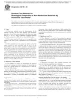
FIG. 2 Insulation Resistance and Resistivity Specimen Holder Brought Through Split-Type Removable Oven Door
9
D229 − 19´1
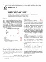
D2 = 21⁄2 in. (63.5 mm) accordance with Practice D5032. Fit the chamber containing
D3 = 3 in. (76 mm) the solution with holders to support the specimen and make
electrical connection for the resistance measurement. Ther-
NOTE 3—Some materials are metal clad. It is potentially desirable to mally insulate the chamber to prevent sudden temperature
utilize the metal foil clad to the insulating material for electrodes. In this changes that can cause precipitation inside the chamber. Fit the
event, follow specifications applicable to the specific material for etching chamber with a small blower or propeller to circulate the air
the clad foil into a suitable electrode pattern. inside. Place the thermally insulated chamber inside an oven
maintained at the specified temperature. Fig. 4 illustrates a
41.2 Electrodes for Insulation Resistance—Metal electrodes suitable humidity test enclosure.
in accordance with Fig. 3 of Test Methods D257 for materials
1⁄32 in. (1 mm) or more in thickness, and in accordance with 43.3 Constant-Temperature Oven—The oven used for el-
Fig. 1 of Test Methods D257 for thinner materials, shall be evated temperature resistance measurements shall conform to
used. the Grade B requirements of Specification E197, except for the
time constant. Fit the oven with holders to support the
42. Test Specimen specimen and make electrical connection for the resistance
42.1 The surface resistance, and therefore also insulation measurements without introducing shunting resistances that
interfere with the measurements. Fig. 2 and Fig. 3 illustrate a
resistance, have the potential to be affected by the manner in suitable arrangement.
which the specimen is prepared, cleaned, and handled. Before
insertion or application of the electrode, clean each specimen 44. Conditioning
to remove release agents or other surface contaminants that can
influence the measurement of resistance. Take care that the 44.1 Resistance properties of materials covered by these test
cleaning procedure does not have a solvent or swelling action methods are very sensitive to moisture and temperature con-
on the material itself. Handle specimens by touching the edges ditions. Controlled conditioning is required.
only. Nylon, rayon, or surgical rubber gloves are recommended
as a precaution against possible contamination of the speci- 44.2 Use any controlled condition to obtain the resistance
mens. information required. The resistance properties of the materials
covered by these test methods are generally so high at fairly
42.2 Specimen for Volume and Surface Resistance Test— dry and room temperature conditions that the resistance values
The specimen shall be a 31⁄2-in. (89-mm) square or disk. have little, if any, practical engineering significance other than
to establish quickly that they are high. The standard conditions
42.3 Specimen for Insulation Resistance Test—The speci- recommended for obtaining useful engineering information are
men shall be a 3 by 2-in. (76 by 51-mm) rectangle for material as follows:
1⁄32 in. (1 mm) or more in thickness. For thinner materials, a
21⁄2-in. (63.5-mm) wide strip, rectangular in shape, shall be 44.2.1 Procedure C of Practice D6054, resistance to be
used. measured while the specimen is in the conditioning
atmosphere, and the conditioning to be accomplished in a
42.4 Test four specimens. forced-air circulated medium.
43. Conditioning Enclosure 44.2.2 Measure the volume resistance of the specimen at the
43.1 Use a conditioning enclosure to provide the specified hottest-spot temperature at which the specimen is expected to
be used, and 15 min after the specimen has reached and been
conditions, to support the specimens, and facilitate electrical maintained at this temperature, as determined by means of a
connections for resistance measurements without introducing thermocouple in the specimen so placed as to measure the
shunting resistances that interfere with the measurements. temperature of the specimen without interfering with the
resistance measurement.
43.2 Humidity Test Enclosure—Obtain the specified relative
humidity at the specified temperature by the use of solutions in 45. Procedure
FIG. 3 Test Specimen for Insulation Resistance and Resistivity 45.1 Determine the insulation resistance, volume resistance
Tests Mounted in Specimen Holder and resistivity, and surface resistance and resistivity in accor-
dance with Test Methods D257 and as further provided in the
following paragraphs.
45.2 At the end of the conditioning period, determine the
presence of shunting resistances. If these cannot be effectively
eliminated by guarding with the instrumentation used, make
proper correction by calculation.
45.3 Measure the resistance of the specimen after applying
500 V of d-c potential difference for 1 min.
46. Precision and Bias
46.1 This test method has been in use for many years, but no
statement for precision has been made and no activity is
planned to develop such a statement.
10
D229 − 19´1
FIG. 4 Humidity Test Enclosure for Insulation Resistance and Resistivity Tests
46.2 A statement of bias is not available because of the lack 51. Test Specimen
of a standard reference material for this property.
51.1 Any specimen 3⁄16 in. (5 mm) or thicker is permitted to
ARC RESISTANCE be tested. The bonding strength is dependent on specimen
thickness, however, and therefore compare only specimens of
47. Procedure the same thickness.
47.1 Determine the arc resistance in accordance with Test
51.2 The standard specimen shall be 0.500 6 0.005 in. (12.7
Method D495. 6 0.127 mm) thick and 1 in. (25.4 mm) square. Two parallel
edges shall be smooth within 60.001 in. (60.025 mm).
TRACKING RESISTANCE
51.3 Test four specimens.
48. Procedure
48.1 Determine the dust-and-fog tracking resistance in ac- 52. Procedure
cordance with Test Method D2132. 52.1 Place the specimen with smooth edge on the testing
48.2 Determine inclined-plane tracking resistance in accor- machine table or a flat steel plate that rests on the testing
machine table. Accurately center the steel ball between the
dance with Test Method D2303 using the variable voltage edges and ends of the specimen.
method.
52.2 Load the specimen through the steel ball, using a
BONDING STRENGTH crosshead speed not exceeding 0.050 in./min (1.3 mm/min)
until the specimen splits. Record the maximum load sustained
49. Significance and Use before or prior to failure.
49.1 The bonding strength is a measure of the adhesive
52.3 Record as the bonding strength the maximum force
strength of a heterogeneous material of the type covered by obtained.
these test methods. It is useful as a manufacturing control or
acceptance test. It is useful to indicate whether or not a 53. Report
thermosetting laminated plastic is properly cured.
53.1 Report the following information:
50. Apparatus 53.1.1 The thickness of the material, and
50.1 Use any universal testing machine, provided it is 53.1.2 The load, expressed in pounds or kilograms, required
to split the specimen.
accurate to 1 % of the lowest load to be applied. The machine
shall be fitted with a head containing a 10-mm diameter steel
ball.
11
D229 − 19´1
54. Precision and Bias to provide test methods that allow the relative comparison of
the ignitability of materials and the extent of burning if ignition
54.1 This test method has been in use for many years, but no does occur.
statement for precision has been made and no activity is
planned to develop such a statement. 61.2 Two methods are provided: Method I, is a relatively
simple test that requires inexpensive apparatus. It is intended
54.2 A statement of bias is not available because of the lack primarily as a control test and for screening quickly materials
of a standard reference material for this property. that exhibit improved fire performance from a population of
various types. Use this method to establish relative burning
ROCKWELL HARDNESS characteristics of tested plastic materials on a comparative
basis. The equipment specified in Method II, which is rela-
55. Procedure tively complex, allows more precise control of test conditions
than Method I.
55.1 Determine the cold Rockwell hardness in accordance
with Test Method D785, except that under Method A use the M 61.3 Neither method will directly produce information from
scale provided that the total indentation does not exceed the which the performance of the insulating material in service can
limits of the testing machine. If the total indentation exceeds be quantitatively predicted, since the conditions of use in
the limits, use the L scale. Test four specimens. electrical apparatus are likely to be different than the test
conditions. In this procedure, the specimens are subjected to
55.2 Determine the hot Rockwell hardness in accordance one or more specific sets of laboratory test conditions. If
with Test Method D785 and Test Method D617. Test four different test conditions are substituted or the end-use condi-
specimens. tions are changed, it is not always possible by or from this test
method to predict changes in the fire-test-response character-
ASH istics measured. Therefore, the results are valid only for the fire
test exposure conditions described in this procedure.
56. Significance and Use
61.4 Both methods provide for the measurement of resis-
56.1 The nature and amount of ash is potentially useful in tance to ignition and resistance to continued burning. Method
determining the continuity of quality and in the interpretation I simply distinguishes between specimens that will ignite
of results of tests for the purposes of design. (under conditions of the test) from those that will not. Resis-
tance to burning is determined by the time the specimen burns.
57. Test Specimen In Method II, it is possible to compare materials directly for
resistance to ignition by determination of ignition time and for
57.1 The test specimen shall consist of 2 to 5 g of finely burning by the burning time. The comparison of burning, or the
divided particles, such as millings or filings, of the material. tendency of the material to contribute to the spread of fire,
requires interpretation regardless of which method is used.
58. Procedure Some materials continue to burn for relatively long periods of
time without the dissipation of much heat energy. Other
58.1 Dry the test specimen for 2 h at 105 to 110°C, weigh, materials burn for relatively shorter periods; however, it is
then ignite to constant weight in a crucible, and weigh. possible that they will burn with potentially damaging inten-
Calculate the percentage of ash, based on the weight of the sity. The determination of weight loss can aid in an interpre-
dried specimen. tation of burning time test results on some materials and is an
additional option by agreement between producer and con-
59. Report sumer.
59.1 Report the following information: Flammability Method I
59.1.1 The identification of the sample tested, and
59.1.2 The percentage ash based on the dry weight of the 62. Apparatus
specimen.
62.1 Flame Cabinet—A draft-free enclosure, test chamber,
60. Precision and Bias or hood equipped with an exhaust fan which is controlled by a
readily-accessible switch.
60.1 This test method has been in use for many years, but no
statement for precision has been made and no activity is 62.2 Supports—A ring stand with a clamping device for
planned to develop such a statement. holding test specimens.
60.2 A statement of bias is not available because of the lack 62.3 Burner—A Tirrill burner having a tube length of 4 in.
of a standard reference material for this property. (100 mm) and an inside diameter of 3⁄8 in. (9.5 mm). The tube
shall have no end attachments such as a flame stabilizer.
IGNITABILITY AND BURNING TIME
62.4 Gas Supply—A methane or natural gas supply having a
61. Significance and Use heat content of approximately 1000 Btu/ft 3 (30 kJ/m3) and a
suitable flow regulator.
61.1 Rigid electrical insulation is sometimes exposed to
temperature sufficiently high to indicate a danger of ignition.
Potential reasons for this are: malfunction of the apparatus of
which the insulation is a part, failure of associated equipment
in the system, or failure of the insulation to resist ignition in
normal-usage exposure to electric arcs. It is therefore desirable
12
D229 − 19´1
62.5 Timer—A timepiece or stop watch measuring seconds. TABLE 1 Laminate Method I Flammability Classes
62.6 Oven—A forced-ventilation oven maintained at 70 6 Class 0 Class 1
1°C (158 6 1.8°F).
First application of flame: 10 30
62.7 Desiccator—A desiccator containing anhydrous cal- Flaming time for single specimen, s
cium chloride or equivalent desiccant.
Second application of flame: 10 30
63. Test Specimens Maximum flaming time for a single specimen, s
Maximum flaming plus glowing time for a 30 60
63.1 Dimensions of test specimens shall be 5 6 1⁄16 in. (12.7 single specimen, s
6 1.6 mm) long by 0.56 0.02 in. (12.7 6 0.51 mm) wide by
the thickness of the sheet. The cut edges of the specimens shall Both applications of flame: 50 250
be smooth and free of projecting fibres. Maximum total time of flaming combustion for five
specimens in each flame application, s
63.2 Cut a total of 20 test specimens without regard to grain
direction (unless this is a variable being studied) and divide 66.1.1 Description of material tested, including thickness
into two sets of 10 specimens each. and whether the sample was copper-clad, and
63.3 Test copper-clad specimens with the copper removed 66.1.2 The laminate shall be classed as Class 0 or Class 1 if
by etching in accordance with Practice D1825. the specimens for both conditioning procedures of Section 64
meet the requirements of Table 1.
64. Conditioning
Flammability Method II
64.1 Condition one set of 10 test specimens for at least 48 h
at 23 6 2°C and 50 6 5 % relative humidity. 67. Apparatus
64.2 Condition the other set of 10 specimens for 168 h in an 67.1 Flame Cabinet—A metal cabinet with heater coil,
oven at 70 6 1°C and then allow to cool for at least 4 h in a spark gaps, specimen holder, access door, and forced-air
desiccator. ventilation as illustrated in Fig. 5, or equipment that gives
equivalent results.
65. Procedure
67.2 Control Cabinet—A control assembly that provides
65.1 Support the test specimen with its 5-in. (128-mm) adjustable, regulated power to the heater coils, ignition voltage
dimensional axis vertical and clamped within 1⁄4 in. (6.3 mm) to the spark gaps, and a timer or timers to indicate the required
of the top at a height such that the lower free end is 3⁄8 in. (9.5 time intervals as illustrated in Fig. 6.
mm) above the top of the burner tube.
67.3 Pyrometer—An optical pyrometer calibrated to read
65.2 With the burner removed from the specimen, ignite the directly for the emission of Nichrome V, or an optical pyrom-
gas and adjust the flame until it is 3⁄4 in. (19.1 mm) high with eter calibrated for black-body emission to which 6°C is added
a blue color and no yellow tip. to the pyrometer reading to obtain the true temperature of the
Nichrome V coil. The pyrometer shall include a scale for
65.3 For each conditioning procedure (see Section 64), test measurement of temperature near 860°C.
one set of five specimens with the second set of five specimens
held in reserve for retesting, if necessary (see 65.6). 67.4 Coil Form—A grooved mandrel on which the
Nichrome V resistance wire is wound into a heater coil as
65.4 Position the burner centrally below each specimen in illustrated in Fig. 7(a).
the first set selected for each condition, allow to remain for 10 s
and then remove. Record the duration of flaming. When 67.5 Coil Spacing Gauge—A spacing gauge constructed of
flaming ceases immediately replace the burner flame under the a sector of a coil form, as illustrated in Fig. 7(b) to check the
specimen for another 10-s interval and then remove. Again coil turn-spacing.
record the duration of flaming and of flaming plus glowing.
68. Test Specimen
65.5 Note if the specimen burns completely in either of the
two flame applications. (A rating cannot be assigned to the 68.1 The specimen shall be 1⁄2 6 0.036 in. (13 6 0.8 mm)
material in this case.) thick or nominal unmachined tolerance by 1⁄2 6 0.01 in. (13 6
0.25 mm) in width by 10 6 1⁄16 in. (254 6 1.6 mm) in length.
65.6 If any one specimen in either set of five specimens for In cases of molded products, the length of the specimen shall
each condition fails to comply with the requirements given in be permitted to be shorter.
Table 1, test a second set of five specimens for that condition.
With respect to the total number of seconds of flaming, test an 68.2 Machine the specimens in a manner that produces a cut
additional set of five specimens if the total is in the range from surface that is free of projecting fibers and ridges.
51 to 55 s for Class 0 material or in the range from 251 to 255 s
for Class 1 material. 68.3 The test sample consists of five test specimens.
66. Report 69. Calibration
66.1 Report the following information: 69.1 Place a dummy specimen in the holder.
13
D229 − 19´1
14
FIG. 5 Flame Cabinet
D229 − 19´1
15
FIG. 6 Electrical Diagram for Control Cabinet
D229 − 19´1
disturb test conditions when the test is performed with properly con-
structed apparatus. However, changing drafts are likely to disturb the
thermal equilibrium condition so that it is possible that the heater coil
temperature will change from the specified temperature even though
constant input power is supplied.
FIG. 7 Mandrel for Coil (a) and Coil Spacing Gauge (b) 71. Procedure
69.2 Adjust the heater coil so that the bottom turn is 11⁄2 in. 71.1 After calibration is completed, use an air jet to cool the
(38 mm) above the top of the specimen holder, the coil is coil to room temperature.
symmetrical about the specimen, and the coil height is 11⁄2 in.
(38 mm). Use the coil spacing gauge to adjust, if necessary, the 71.2 Insert the specimen in the holder with the cut side
individual coil turns for proper spacing. facing the spark gaps. (When testing laminates, make the plane
of laminations parallel to the plane of the front of the
69.3 Adjust the spark gap to 3⁄16 6 1⁄16 in. (5 6 1.6 mm) and apparatus.) Close the peep-hole.
determine that the arc is in an approximate horizontal plane.
The total (in both electrodes) arc-current shall be 20 6 5 mA. 71.3 Move the arc electrodes to the horizontal position.
The electrode tips shall be approximately 1⁄8 in. (3 mm) in a Energize the ventilating blower.
horizontal plane from the specimen and 1⁄2 in. (13 mm) above
the top turn of the heating coil. 71.4 Simultaneously energize the heater coil, arc gap, and
timer circuit.
69.4 Remove the dummy specimen. Close the door and
energize the ventilating blower. Energize the heating coil and 71.5 Record the elapsed time in seconds when the test
adjust the heater current to approximately 55 A. Allow the coil specimen ignites as ignition time, I.
to come to equilibrium temperature (approximately 120 s). If a
new coil is being used, reduce the current to 50 A and allow to 71.5.1 Ignition time is determined from the instant that the
remain energized for 24 h to produce a stable oxide coating. specimen bursts into flame rather than from the instant of gas
flame ignition.
69.5 Open the peep-hole in the door; sight the optical
pyrometer on the outside of the middle turn and adjust the 71.5.2 It is possible that gases released from the specimen
heater current to obtain an equilibrium temperature of 860 6 will ignite before the specimen commences burning.
5°C. Keep the peep-hole closed during test.
71.6 De-energize the heater and spark gaps 30 s after the
69.6 After the current has been adjusted, the variable-ratio specimen ignites; move the arc electrodes away from the
autotransformer setting must not be disturbed during the test. specimen.
In order to maintain the temperature within 65°C, it is
necessary that the average rms voltage across the heater remain 71.7 De-energize the timer circuit when the specimen
constant within 61.0 %. ceases to burn (all flame has disappeared), and record the total
elapsed, T, in seconds.
70. Conditioning
71.8 Before beginning the next test, cool the coil with an air
70.1 Condition specimens for 168 h in the Standard Labo- jet, brush soot and contamination from the heater coil and arc
ratory Atmosphere (23°C, 50 % relative humidity) except that gaps, and blow any debris from the test enclosure.
when it is demonstrated that test results for the specific type
material are not significantly affected by conditioning, the use 72. Calculation
of unconditioned specimens is permitted.
72.1 Burning Time—Calculate the burning time, B, in
70.2 Conduct tests in a room that is controlled at the seconds, as follows:
Standard Laboratory Atmosphere (Note 4) and is free of
spurious drafts (Note 5). B 5 T 2 I 2 30 (3)
NOTE 4—It is a well-established fact that the combustion process is where:
influenced by the moisture content of the oxygen-providing atmosphere.
T = total elapsed time, and
NOTE 5—Drafts, except those of unusual velocity, are not likely to I = ignition time.
Calculate the burning time by arranging the five values of
burning time in increasing order of magnitude, as T1, T2, T3, T4,
and T5. Compute the following ratios:
~T2 2 T1!/~T5 2 T 1!
and
~T5 2 T 4!/~T5 2 T1!
If either of these ratios exceeds 0.642 then T1 or T5 is judged
to be abnormal and is eliminated. Report the burning time as
the average of the remaining four values.
72.2 Average Ignition Time—Calculate the average ignition
time as the arithmetic mean of the five specimens.
16
D229 − 19´1
73. Report 79. Calculation
73.1 Report the following information: 79.1 Calculate the percentage warp or twist based on a
73.1.1 Nominal thickness of the test specimen, 36-in. (914-mm) length as follows:
73.1.2 Average and individual burning times and ignition
times, and W914 5 ~914D/L2! 3 100 (4)
73.1.3 Description of how the specimen burns with particu-
lar attention to the intensity of the flame. or
73.1.4 Burning time of each specimen and average burning
time. W36 5 ~36D/L2! 3 100 (5)
73.1.5 Ignition time of each specimen and average ignition
time. where: percentage warp or twist calculated to a 914-mm
W914 = length, or
74. Precision and Bias W36 = percentage warp or twist calculated to a 36-in.
D= length,
74.1 This test method has been in use for many years, but no maximum deviation in millimetres or inches of the
statement for precision has been made and no activity is L= sheet from the straight-edge, and
planned to develop such a statement. length in millimetres or inches of the dimension
along which the warp or twist is measured.
74.2 A statement of bias is not available because of the lack
of a standard reference material for this property. 79.2 When it is desired to compare the actual deviation for
any length with the permissible deviation for that length, use
COEFFICIENT OF LINEAR THERMAL EXPANSION the following equation:
75. Procedure Dx ⁄ D914 5 Lx2⁄~914!2 (6)
75.1 Test a minimum of two specimens in accordance with or
Test Method D696.
Dx ⁄ D36 5 Lx2⁄~36!2 (7)
WARP OR TWIST
where: permissible deviation from straight-edge in milli-
76. Significance and Use Dx = metres or inches for the given length,
permissible deviation in millimetres for 914-mm
76.1 Warp and twist are expressions of deviation from D914 = length, or
flatness of a material. The extent of deviation is of interest permissible deviation in inches for 36-in. length, and
primarily when it is intended to fabricate the sheet or plate D36 =
material, but also has the potential to affect the ability to use
the full-size sheet in an assembly. Lx = given length in millimetres or inches.
77. Conditioning NOTE 6—These requirements do not apply to cut pieces, but only to
sheet sizes as manufactured.
77.1 It is generally not necessary to condition the material.
Where conditions of storage have the potential to cause warp or 80. Report
twist, condition the material in a manner agreed to by the
purchaser and the supplier. 80.1 Report the following information:
80.1.1 The identification of the sample tested, and
78. Procedure 80.1.2 The percent warp or twist based on a 36-in. (914-
mm) length.
78.1 Determine the warp or twist on the sheet in the
as-received condition by holding a straightedge along the 81. Precision and Bias
dimension to be measured. Place the concave side of the sheet
adjacent to the straightedge. Measure the greatest deviation of 81.1 This test method has been in use for many years, but no
the concave surface from the straightedge by a metal scale. statement for precision has been made and no activity is
planned to develop such a statement.
78.2 Warp—Measure the warp by suspending the sheet
freely from the center of one edge in a vertical position against 81.2 A statement of bias is not available because of the lack
a horizontal straightedge, then in succession by the other edges of a standard reference material for this property.
until the point of maximum warp is obtained.
ACETONE EXTRACTABLE MATTER
78.3 Twist—Measure the twist by suspending the sheet in a
vertical position from adjacent corners, singly and in 82. Procedure
succession, and then measuring the deviation along the diago-
nal from the straightedge connecting the corners opposite from 82.1 Determine the acetone extractable matter in accor-
the vertical. Report the maximum twist. dance with Test Method D494.
83. Precision and Bias
83.1 It is important that duplicate determination by different
operators not differ by more than 6 0.5 % extractable matter
for values under 5.0 % and 61.0 % for values 5.0 to 12.0 %.
17
D229 − 19´1
83.2 This test method has no bias because the value for ability; impact resistance; insulation resistance; permittivity;
acetone extractable matter is determined solely in terms of this printed wiring boards; resistivity; rigid plates; rigid sheets;
test method. Rockwell hardness; solvent extractible; spacers; surface resis-
tance; surface resistivity; tensile strength; terminal boards;
84. Keywords thermal expansion; thermosetting laminate; thickness; tracking
resistance; twist; voltage barriers; volume resistivity; warp;
84.1 ac breakdown voltage; arc resistance; ash content; water absorption
bond strength; burning time; compressive strength; dissipation
factor; elastic modulus; flexural strength; hard rubber; ignit-
SUMMARY OF CHANGES
Committee D09 has identified the location of selected changes to this standard since the last issue (D229 – 13)
that may impact the use of this standard. (Approved March 1, 2019.)
(1) Revised 1.4. (5) Deleted Section 67 (and moved the definitions to Section
(2) Revised terminology section. 3). Renumbered subsequent sections accordingly.
(3) Revised 61.1 – 61.3. (6) Revised section on report of Flammability Method I.
(4) Revised titles of fire tests and of Table 1. (7) Revised keywords.
ASTM International takes no position respecting the validity of any patent rights asserted in connection with any item mentioned
in this standard. Users of this standard are expressly advised that determination of the validity of any such patent rights, and the risk
of infringement of such rights, are entirely their own responsibility.
This standard is subject to revision at any time by the responsible technical committee and must be reviewed every five years and
if not revised, either reapproved or withdrawn. Your comments are invited either for revision of this standard or for additional standards
and should be addressed to ASTM International Headquarters. Your comments will receive careful consideration at a meeting of the
responsible technical committee, which you may attend. If you feel that your comments have not received a fair hearing you should
make your views known to the ASTM Committee on Standards, at the address shown below.
This standard is copyrighted by ASTM International, 100 Barr Harbor Drive, PO Box C700, West Conshohocken, PA 19428-2959,
United States. Individual reprints (single or multiple copies) of this standard may be obtained by contacting ASTM at the above
address or at 610-832-9585 (phone), 610-832-9555 (fax), or (e-mail); or through the ASTM website
(www.astm.org). Permission rights to photocopy the standard may also be secured from the Copyright Clearance Center, 222
Rosewood Drive, Danvers, MA 01923, Tel: (978) 646-2600; />
18