AIREMANAGER NETWORK MANAGEMENT PLATFORM (STANDARD) REVISION D 4: AIREMANAGER ™ SETUP AND USER’S GUIDE
Bạn đang xem bản rút gọn của tài liệu. Xem và tải ngay bản đầy đủ của tài liệu tại đây (1.61 MB, 32 trang )
LightPointe - AireManager Setup and User’s Guide
AireManager
AireManager Network
Management Platform for
Aire product line
Setup and User’s Guide
Revision D.4
LightPointe - AireManager Setup and User’s Guide
Copyrights and Disclaimer
2011, LightPointe. All Rights Reserved
Information in this document is provided in connection with LightPointe products.
These materials are provided by LightPointe as a service to its customers and may
be used for information purposes only. LightPointe assumes no responsibility for
errors or omissions in these materials. LightPointe may make changes to
specifications and product descriptions at any time, without notice. LightPointe
makes no commitment to update the information and shall have no responsibility
whatsoever for conflicts or incompatibilities arising from future changes to its
specifications and product descriptions.
No license, express or implied, by estoppel or otherwise, to any intellectual property
rights is granted by this document. Except as provided in LightPointe Terms and
Conditions of Sale for such products, LightPointe assumes no liability whatsoever.
These materials are provided “as is” without warranty of any kind, either expressed
or implied, relating to sale and/or use of LightPointe products including liability or
warranties relating to fitness for a particular purpose, consequential or incidental
damages, merchantability, or infringement of any patent copyright or other
intellectual property right. LightPointe further does not warrant the accuracy or
completeness of the information, text, graphics or other items contained within these
materials. LightPointe shall not be liable for any special, indirect, incidental, or
consequential damages, including without limitation, lost revenues or lost profits,
which may result from the use of these materials.
LightPointe products are not intended for use in medical, lifesaving or life sustaining
applications. LightPointe customers using or selling LightPointe products for use in
such applications do so at their own risk and agree to fully indemnify LightPointe for
any damages resulting from such improper use or sale.
The following are trademarks of LightPointe Product names or services listed in this
publication are for identification purposes only, and may be trademarks of third
parties. Third-party brands and names are the property of their respective owners.
FligħtLite, FligħtStrata, FligħtManager, AireLite, AireBeam, AireForce,
AireManager and HyBridge are trademarks of LightPointe.
LightPointe believes the printed matter contained herein to be accurate from date of
publication and reserves the right to make changes as necessary without notice.
Reader Response: LightPointe strives to produce quality documentation and
welcomes your feedback. Please send comments and suggestions to LightPointe. For
technical questions, contact your local LightPointe sales office or field applications
engineer.
AireManager Network Management Platform (Standard) Revision D.4 Page ii
LightPointe - AireManager Setup and User’s Guide
Table of Contents
1. Quick Setup Reference 4
2. Introduction 5
2.1. Cabling 5
2.2. Direct Serial Connection to the Aire RJ-12 Port 6
2.3. Telnet and Password changes 6
2.4. Browser-based Management Application 6
2.5. SNMP 7
3. Step by Step Configuration 7
4. Management Application 10
4.1. Management Application Views 10
4.1.1. System View 11
4.1.2. FSO/MMW View 13
4.1.3. Software View 16
4.1.4. Management View 17
4.1.5. Statistics View 18
5. AireManager Network Management Options 19
5.1. In Band / Out of Band Management Access 19
5.2. Illustration of Management Schemes 21
5.2.1. Symmetrical Management Schemes 21
5.2.2. Asymmetrical Management Schemes 22
5.3. Examples of Management Configurations 23
6. Telnet Access 26
6.1. Connecting with Telnet to Change Passwords 26
6.2. Overview of Other Telnet Command Line Options 27
7. Network Interface Configuration Examples 28
8. Firmware Reinstallation or Upgrade 29
8.1. Walkthrough: Reloading System Files 29
AireManager Network Management Platform (Standard) Revision D.4 Page 3
AireManager Setup and User’s Guide Quick Setup Reference
1. Quick Setup Reference
When first receiving your Aire (short for AireLite, AireStrata, AireBeam) system:
Step 1 In an office or lab environment:
Connect a CAT5e or CAT6 cable to the PoE/Management port on the Aire
system. Connect the other end to the Output of the provided PoE
Injector.
Connect the AC power cable of the PoE Injector to a 110-240VAC power
source to power.
Power on the unit using the power switch on the system back panel.
Connect the provided RJ-12 cable to the Serial Port of the Aire system.
Connect the other end to the provided RJ-12 to DB9 Modular Adapter.
Use a serial cable to connect the DB-9 Modular Adapter to your PC or
laptop. In case your laptop/computer does not have a serial port, please
use an USB-to-serial converter.
Use a terminal application to make a connection to the AireManager
firmware. See chapter 3, Step by Step Configuration
Change the master password and set the IP parameters.
See chapter 3, Step by Step Configuration
Step 2 Connect a CAT5e or CAT6 cable to the Input port of the PoE Injector.
Connect the other end to the network card of your PC or laptop.
Open a command line terminal and telnet to the IP address you assigned
to the Aire system. See chapter 5, Telnet Access
Set the Admin, Guest and Technician passwords.
See chapter 5, Telnet Access
Step 3 Perform the same steps on the other Aire unit.
AireManager Network Management Platform (Standard) Revision D.4 Page 4
AireManager Setup and User’s Guide Introduction
2. Introduction
This chapter covers the following main topics:
Introduction to AireManager
Physical Cabling
Serial Connection
Telnet Connection
AireManager Browser-based Management Application
SNMP
The AireManager software platform is used to monitor and configure LightPointe Aire
products. The management access options can be changed within the AireManager
management software.
IMPORTANT NOTE:
All MMW and Optical Wireless Aire systems are pre-configured with the option “Out of Band
Management” enabled (see Chapter 4.1.5). This configuration allows managing the system
via the out of band management port, the same port used to power the system via the PoE
injector supplied with the system. To access the management system the out of band
management port must be connected to the network and the web browser based
AireManager management system can easily be accessed by executing the
http://system_Ipaddress command.
The status information sent from the Aire system to the browser-based manager or to
your SNMP management application can be used to monitor system performance or
diagnose system problems. The AireManager firmware can be accessed remotely, over a
network, using the browser-based management application, allowing for bi-directional
access including monitoring and configuration, as well as acting as an SNMP reporting and
configuration agent, sending out SNMP traps and serving requests from your own network
SNMP manager. The separate and dedicated Out-of-band Management Port provides faster
device response, and additional network security.
2.1. Cabling
The AireManager data is transferred to and from the radio unit to a standalone PC or
network via an in-band or out-of-band management connection. Out-of-band management
traffic is carried over a dedicated CAT5E or CAT6 cable, separate from the network data
connection of the Aire unit. The management data is sent and received on the port labeled
PoE and Out-of-band Management Port. This is the same port used to power the Aire unit
via the passive PoE injector that comes with the system. The cable lengths between the
radio units and the switch or PC should not exceed 100 meters. Besides the two CAT5E
connections (or alternative a SM/MM fiber connection to the SFP port), an RJ-12 cable is
required for connecting to the Serial Port of the Aire unit.
Note: The Serial Port connection is in general only required during the initial system setup
or in case a complete reload of the bootloader would be required. After the initial setup, all
firmware/ software updates can be performed via the Ethernet based Management
connection.
AireManager Network Management Platform (Standard) Revision D.4 Page 5
AireManager Setup and User’s Guide Introduction
2.2. Direct Serial Connection to the Aire RJ-12 Port
It is recommended to use this method before installing the Aire units at their permanent
locations. It is the ONLY method provided for changing the Master Password of the
AireManager platform. The Master Password is used for both Terminal port and Telnet
access over a network.
Note: When receiving the Aire units the default Master Password is set to ‘LightPointe’.
An RJ-12 to DB-9 conversion kit is provided with your Aire units for making a connection
to the Serial Port. You are required to provide your own serial cable. You may require a
USB-to-DB-9 serial adapter if the PC or laptop does not have a DB-9 connector.
In addition to setting the Master Password, the IP configuration information and SNMP
community strings can be set using this method.
The Serial Port connection is required when upgrading/re-installing the system
bootloader software. This should however only be required under very rare circumstances
like a catastrophic software failure. The Serial Port connection can also be used when
upgrading or reinstalling the AireManager web content file and/or firmware, when updates
become available. While the firmware as well as the web content file can be easily upgraded
using the AireManager browser-based management application, upgrading firmware over a
network presents a higher potential for failure than a direct serial connection. Instructions
are provided with the content or firmware upgrade.
Using a terminal application such as HyperTerminal or TeraTerm Pro (can be downloaded
for free at ), the correct COM port connection settings are
as follows:
Bits per second: 19200
Data bits: 8
Parity: None
Stop bits: 1
Flow control: None
2.3. Telnet and Password changes
Telnet connectivity is necessary to change the default Admin, Guest and Technician
passwords used for accessing the AireManager browser-based management application.
Refer to chapter 5, Telnet Access for detailed instructions.
2.4. Browser-based Management Application
AireManager is most commonly accessed over a network using this Java applet running in a
web browser such as Internet Explorer, Safari, or Mozilla Firefox. Java version 1.5 or greater
is required. The browser-based manager allows for the monitoring of the Aire unit,
configuration of the network monitoring software and SNMP trap destinations, system
registration and storage of installation details. No additional software is required. Refer to
chapter 4, Management Application.
AireManager Network Management Platform (Standard) Revision D.4 Page 6
AireManager Setup and User’s Guide Step by Step Configuration
2.5. SNMP
MIBs for the Aire system are provided with the units and can be loaded into your networked
SNMP Manager. The Aire units send trap information to the IP trap destinations entered into
the browser-based management application, and serves authenticated GET and SET
requests. Most SNMP managers are capable of tracking the Aire connection and
performance over time and displaying the data in graphical format.
3. Step by Step Configuration
Before installing the Aire units in their permanent locations it is recommended that the
administrator first power the units and connect directly using a serial connection to change
the Master Password and set IP information. The following items are required:
An Aire unit
A Workstation, PC or Laptop
A terminal application such as HyperTerminal or TeraTerm Pro
An RJ-12 to DB-9 modular adapter (provided with the system)
An RJ-12 cable (provided with the system)
An USB-to-DB9 serial adapter in case the PC has no serial port interface (not
provided with the system)
Steps taken to connect to and configure the AireManager for IP:
Step 1 Connect the PoE And Out-of-band Management Port on an Aire unit to the
Output of the PoE Injector using a straight-through Cat5E cable. Plug the PoE
Injector into a 110 or 240VAC outlet. The Aire unit will now power up. Wait 1-2
minutes for the AireManager platform to initialize.
Step 2 To connect the Aire system to the serial port of your laptop/ computer, please
locate the RJ-12 cable and the RJ-12 to DB-9 modular port adaptor shipped
with the system. Connect the RJ-12 cable to the RJ-12 Serial Port of the Aire
unit. Connect the other end to the RJ-12 cable to the DB-9 modular adapter.
Connect a serial cable to the modular adapter and connect the other end of the
serial cable to the PC or laptop. An additional standard USB to serial converter
is needed if the PC or laptop does not have a DB-9 port
Step 3 Open HyperTerminal or another terminal application on the PC or laptop.
Select the correct COM port (settings: 19200 bps, 8 bit, parity None, 1 stop
bit, flow control None) and make the connection. Hit enter. The following
message will be displayed
For restoring factory defaults use ‘restore’
For setting new license key use ‘setlic’
AireManager Network Management Platform (Standard) Revision D.4 Page 7
AireManager Setup and User’s Guide Step by Step Configuration
Step 4 The firmware must be rebooted to enter the setup dialogue
Step 5
Step 6 Type ^^^ and hit enter to reboot the firmware
The system will countdown from 7 and then reboot
Hit any key within 3 seconds of startup to enter the setup dialogue
Please enter CLI password:
Your default master password is LightPointe. This password is also valid for
TELNET access (see chapter 5).
Change password? [Y/N]:
Type Y and hit enter
Please enter new password:
Type your new password and hit enter
Storing updated bootrecord…done
Please enter IP parameters
Aquire IP configuration using DHCP? [N]
The default is no. Make your choice and hit enter
IP address [192.168.1.115]:
The number in brackets is the default. Make your change and hit enter
Netmask [255.255.255.0]:
Make your change and hit enter
Default gateway [192.168.1.1]:
Make your change and hit enter
Modify the above or continue? [M/C]
Hit C and then enter
AireManager Network Management Platform (Standard) Revision D.4 Page 8
AireManager Setup and User’s Guide Step by Step Configuration
Step 7 Please enter new boot parameters
Step 8 In this part of the dialogue one needs to setup the SNMP community
environment. Standard is public/private and this is the ONLY place to cange to
a different setting.
SNMP GET community [public] -
Specify/type SNMP GET community or hit return for Default “public”
SNMP SET community [private] –
Specify/type SNMP SET community or hit return for Default “private”
TFTP server address [192.168.1.1]
Setting the TFTP server adress is optional and can be configured later using
the browser-based AireManager management application.
Enter new TFTP server address or accept the default for TFTP address
TFTP filename [ ]
No need to specify a TFTP fileneame, hit return
Boot operation [1.Download image, 2.Download content, 3.Run]
Type 3 and hit enter
Modify the above or continue? [M/C]
Hit C and then enter
Current boot parameters are then displayed. The firmware stores the updated
bootrecord, initializes the telnet interface, and verifies the checksum. When the
CIU system running… message is displayed the unit can be powered off and
installed at its permanent location
Perform the same steps on the other Aire unit
AireManager Network Management Platform (Standard) Revision D.4 Page 9
AireManager Setup and User’s Guide Management Application
4. Management Application
This chapter covers the following main topics:
Explanation of AireManager management application views and data
4.1. Management Application Views
To connect to the AireManager browser-based management application, open a web-
browser on the same network as the Aire unit and enter the IP address of the Aire unit in
the address/URL field. There are three available logins:
User Name Default Password
Guest guest
Admin admin
Technician tech
These default passwords can only be changed via telnet (refer to chapter 5, Telnet Access).
If the SNMP community strings were changed from their defaults at any point, using serial
connection or this management application, they will need to be entered correctly at login
from this point forward. Otherwise the defaults will remain and won’t have to be entered as
part of the login.
When first logging into the AireManager management application you are presented with
the registration screen. This screen will appear every time you log into the application, until
the registration process has been completed. Please complete the registration process.
On the left side of the AireManager browser-based management application you will see
a window with several navigation icons. When using the AireManager, there are five
navigation icons: System, FSO, MMW, Software, Management and Statistics.
Note: In case of an FSO system, the MMW icon will be grayed out and vice versa.
The management functionality for either system will however be the same. Clicking on an
icon initiates a new view. The values and options displayed are a function of SNMP GET and
SET commands. A picture of the specific system monitored/managed is displayed in the
middle of the browser window.
AireManager main screen for all MMW and FSO Aire systems.
AireManager Network Management Platform (Standard) Revision D.4 Page 10
AireManager Setup and User’s Guide Management Application
4.1.1. System View
The System View includes the following data:
General Information
Description: Indicates CIU Management Agent
UpTime: Indicates the time the unit has
been in operation since the last
power cycle
Name: Indicates the name of this
particular Aire unit. A fully
qualified domain name is most
desirable
Location: Indicates the location of this
particular Aire unit
Contact: Indicates the name or other
identifier of the system
administrator
Environment Indicates the internal temperature
Temperature: of the unit in degrees Celsius
System Information
FW Version: Indicates the AireManager firmware
version
HW Indicates the Aire system hardware build
Revision: version
MAC Indicates the MAC address of this
Address: AireManager interface board
AireManager Network Management Platform (Standard) Revision D.4 Page 11
AireManager Setup and User’s Guide Management Application
Installation Information*
Name: Indicates the name of this installation site
Address: Indicates the address of this installation site
By: Indicates the name of installer
Date: Indicates the date of installation
Phone: Indicates the phone number of installer or
installation company
Email: Indicates email of the same
RSSI: Indicates the receive level at the time of
installation or last boot of firmware
Contact Info
Name: Indicates the name of the system
administrator
Phone: Indicates the phone number of the system
administrator
Mobile: Indicates the cellular phone number of the
system administrator
Email: Indicates the email address for the system
administrator
System Reset/Restore
Reset Click this button to reboot the AireManager
Device: software
Restore Click this button to restore the AireManager
Factory software to the factory defaults
Defaults:
*These fields are provided for both sites A and B.
The units do not share this information so the data
must be entered for each unit.
AireManager Network Management Platform (Standard) Revision D.4 Page 12
AireManager Setup and User’s Guide Management Application
4.1.2. FSO/MMW View Depending on the system to be monitored, either
the FSO or the MMW icon can be selected, and
the FSO/MMW View menu will appear. This view
is most useful for configuring the functionality of
the fiber and copper Data Ports of the Aire unit
and for diagnosing potential system problems.
The following data is included:
MMW View Indicates the Aire model
Status
Model:
Configuration: Standard: System operates in
Standard configuration
RSSI (dBm): mode
RSSI LOW
Threshold: Indicates the current receive level (mV)
of this unit.
RSSI HIGH
Threshold: Sets the low RSSI alarm threshold in
mV. A drop in RSSI below this level
triggers the RSSILow alarm trap
Standard settings: FSO: 250 mV;
MMW: 400 mV
A rise in RSSI above this level from a
previous low RSSI alarm condition
triggers the RSSIClear alarm trap.
By setting this value a few mV higher
than the RSSI Low Threshold, RSSI
values hovering around the alarm
threshold are less likely to trigger
alarm flapping, or the frequent,
spurious generation of traps
Standard settings: FSO: 300 mV;
MMW: 450 mV
Heater and Tracking Status (FSO systems ONLY!)
Heater Indicates if internal front glass heater is
Status: turned ON or OFF
Heater Sets the threshold temperature for
Threshold: heater to turn ON. Note: This is not
the outside temperature, but the
temperature as measured inside the
unit.
AireManager Network Management Platform (Standard) Revision D.4 Page 13
AireManager Setup and User’s Guide Management Application
Tracker Indicates if tracker switch on the back
Status: plane of the AireStrata system is turned
ON or OFF
Fiber (SFP) Network Connection
Status: Indicates a Connect status when an SFP
module has been properly inserted into
the SFP Port or Disconnect if no SFP
module is detected. A Connect status is
required to report the data below.
Link: Indicates an Up status when the
SFP/Fiber Port is connected to an
enabled switch or router interface, or
Down status when disconnected
Activity: Indicates the presence, Traffic, or
absence, No Traffic, of data at the SFP
interface (traffic received from an
attached switch or router interface)
Part Number: Indicates the part number of the SFP
transceiver
Transceiver: Indicates the hex value of the unique
transceiver identifier
Temperature Indicates the temperature at the SFP
(C): transceiver for SFP modules with this
capability
TX Power Indicates the transmit power of the SFP
(dBm): transceiver in dBm
RX Power Indicates the receive power of the SFP
(dBm): transceiver in dBm
RX Low Alarm: Indicates Normal is no alarm condition
exists or Alarm if the receive power at
the SFP interface is below the low
threshold
SFP Sets the Enabled or Disabled status of
Transmission: the SFP transceiver
Settings Status
Control Flow: Sets the Enabled or Indicates Control
Copper (RJ45) Disabled status of flow status
Ethernet control
flow on the SFP
interface (default:
disabled)
Network Connection
AireManager Network Management Platform (Standard) Revision D.4 Page 14
AireManager Setup and User’s Guide Management Application
Link: Indicates the Up or Down status of the link
between the Aire copper interface and the
network switch or router
Activity: Indicates the presence, Traffic, or absence,
No Traffic, of data between the Aire system
and the network switch or router
Port: Settings Status
Mode:
Speed: Sets the port Indicates On or Off
On or Off
Duplex: Indicates Manual or
Sets the mode Auto-Negotiate
Manual or
Auto-Negotiate Indicates the speed
Sets the speed 100 of the copper
or 1000 Mbps (if interface (100 or
Mode is set to 1000 Mbps)
Manual)
Indicates setting of
Sets the duplex Full copper interface
or Half (if Mode is duplex setting
set to Manual)
Settings Status
Control Flow: Sets the Enabled or
Disabled status of
Ethernet control flow Indicates control
on the RJ45 inter- flow status
face (default:
disabled)
Network Interface Configuration
Primary Port: Allows to set primary port to
either SFP (Fiber) or RJ45
(Copper)
Secondary Port: Allows to set the secondary
port to either SFP (Fiber) or
RJ45 (Copper)
Mode: Set network interface mode of operation:
Turn Primary Port Off
Turn Secondary PORT Off
Enable Add/Drop operation e.g. connection of IP camera to secondary port
AireManager Network Management Platform (Standard) Revision D.4 Page 15
AireManager Setup and User’s Guide Management Application
4.1.3. Software View
The Software View allows for viewing the loaded software modules and
uploading AireManager content and firmware files via the Ethernet network
management port.
Files Indicates the type, name and size of firmware and
content files currently stored on the Aire unit
Type,
Name,
Size:
Download/Upload
File Name: Indicates the name of the file to be up/downloaded
Command: Only the Download Image and Download Content
options need ever be selected. Ready and Busy are
messages and not actual commands
Status: Indicates when content or firmware is being
uploaded, or when complete
Progress: Progress of the file being transferred in bytes
File Server Indicates the IP address of the TFTP server hosting the firmware or content
upgrade file(s)
TFTP IP
Address:
AireManager Network Management Platform (Standard) Revision D.4 Page 16
AireManager Setup and User’s Guide Management Application
4.1.4. Management View
The Management view includes the following settings:
Out of Band Port
Status: Indicates the connection status of the out of band and
port based VLAN management port.
Security
Access: Management ports and access levels to be assigned by
the network administrator (see chapter 5 for details).
Note: Default setting for systems shipped is “All
Ports”.
VLAN ID: VLAN ID assigned by the network administrator. This
setting only applies when VLAN operation is enabled.
Note: The out-of-band port does not assign a VLAN ID
to the management traffic. In case VLAN tagging is
required, a VLAN ID can be assigned by the switch port
connected to the out-of-band management interface.
VLAN Indicates if VLAN operation is enabled/disabled
Enable:
IP Settings
IP Address: Indicates the management IP address of this Aire unit
Subnet Mask: Indicates the subnet mask of this Aire unit
Default GW: Indicates the default gateway IP for this Aire unit
GET Indicates the GET community string used by your SNMP management application
Community:
SET Indicates the SET community string used by your SNMP management application
Community:
Trap Destinations
IP Address: Set and view the IP address of the device(s) where traps should be directed
AireManager Network Management Platform (Standard) Revision D.4 Page 17
AireManager Setup and User’s Guide Management Application
4.1.5. Statistics View
The Statistics view allowing viewing of the Ethernet switch RMON counters
for the Fiber (SFP), Copper (RJ45), and radio link port.
Ethernet Statistics
Fiber (SFP) Port Copper (RJ45) Port Link
Color-coded connectivity and CRC error counter Status*
Grey – no traffic was received Grey – no traffic was received Grey – no traffic was received
Green – low error rate (<0.1%) Green – low error rate (<0.1%) Green – low error rate (<0.1%)
Yellow – medium error rate Yellow – medium error rate Yellow – medium error rate
(0.1% - 0.5%) (0.1% - 0.5%) (0.1% - 0.5%)
Red – high error rate Red – high error rate Red – high error rate
(above 0.5%) (above 0.5%) (above 0.5%)
List of RMON counters List of RMON counters List of RMON counters
* For a detailed readout of CRC error counter statistics open the Statistics Tab
when logged in as Technician.
AireManager Network Management Platform (Standard) Revision D.4 Page 18
AireManager Setup and User’s Guide AireManager Network Management
Options
5. AireManager Network Management Options
The AireManager software provides several management options that can be assigned by the
network administrator using the Management menu settings illustrated in section 4.1.4. We will
now explain these options in more detail.
5.1. In Band / Out of Band Management Access
The AireManager software provides the flexibility to allow full/unrestricted access or
limited/restricted access to the system management CPU from a local or remote site. It is
possible to assign both, symmetrical as well as asymmetrical management schemes and use an
in-band or out-of-band management approach.
For an out-of-band management architecture the system is equipped with an out-of-band
networking connection. When selecting the out-of-band mode of operation the management
traffic and the network data traffic are completely separated. Management traffic terminates at
the management CPU and the only access path to the management traffic is through the
management port. At the same time, it is not possible to access the networking data traffic
through the management port. Out-of-band management is very popular with customers using a
physically separated management network. This allows access to crucial networking
infrastructure in case the data network is down and not functional at all. Some organizations also
use out-of-band management access to a networking element in conjunction with VLAN tagging
of the management traffic on the data network (see chapter 5.3 for more specific network
configuration examples).
In case the administrator uses the in-band management option, the management information
is included with the regular network traffic and the management traffic is injected into the
Ethernet network traffic port(s). To logically separate the in-band management traffic and the
network data traffic, the customer can assign a specific VLAN ID to the management traffic.
When VLAN operation is enabled on the attached networking switch port, only the management
packets that have the proper VLAN ID are forwarded to the internal management CPU and CPU
tags all outgoing packets with the same VLAN ID. This procedure does not only separate the
management traffic, but also helps with the CPU response time to specific management request
issued by the management software.
The management configuration parameters can be accessed from the “Security” tab in the
“Management” window (see section 4.1.4)
Note:
In the case the management system is not accessible due to a mistake performed during
configuration, typing the command “SD” in the serial interface AireManager window can be used
to display the management configuration. Subsequently typing “RSTSEC” can be used for
restoring the management system to the default “All Ports” and none VLAN based architecture.
AireManager Network Management Platform (Standard) Revision D.4 Page 19
AireManager Setup and User’s Guide AireManager Network Management
Options
FSO Transceiver /
MMW Module
SERDES AireBeam Z60 RSSI and Status/Control
(CDR) ONLY Signals
Altera FPGA
Marvell GbE switch Dallas Microprocessor
(Inband/Outband (Webbrowser, SNMP, Control)
Management, Backup)
LED RSSI Bar RS232 port
SFP Cage assembly: RJ45 copper port
1000 Base-TX RJ45 10/100 Base-TX
1000 Base-SX/LX fiber PoE
Primary Data Port Out-of-Band Management
Backup Data Port
RJ45 copper port
100/1000 Base-TX
Primary Data Port
Backup Data Port
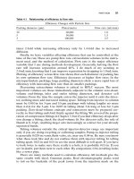
Schematic view of the Networking Interface Architecture.
The Aire network interface has two data traffic ports that can be assigned to transport in-band
management traffic. The out-of-band management port is terminated directly at the
Microprocessor that handles the network management communication. This port can be
connected to a passive PoE injector (supplied by LightPointe) to power the system. The RS232
port is used for initial setup and to reload software in case of a catastrophic software failure.
AireManager Network Management Platform (Standard) Revision D.4 Page 20