SS YNCHRONIZEYNCHRONIZE RRAUTOMATIC AUTOMATIC TROUBLESHOOTING GUIDE
Bạn đang xem bản rút gọn của tài liệu. Xem và tải ngay bản đầy đủ của tài liệu tại đây (2.71 MB, 15 trang )
AUTOMATIC
SYNCHRONIZER
TROUBLESHOOTING GUIDE
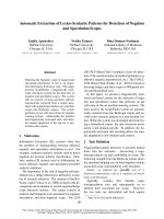
SOLENOID RELAY ASSEMBLY
(MODEL 1750)
LIMIT SWITCH
ENGINE CABLE — CABLE
TO ENGINE THROTTLE
“RED COLLAR”—ADJUST
LIMIT SWITCH OPERATION
“BRIDGE CABLE”—CONTROL
CABLE TO HELM STATION
GUIDE BRACKET BRIDGE CABLE TERMINAL—
ADJUST HERE FOR BRIDGE
CABLE OVERTRAVEL
LIMIT SWITCH BRIDGE CABLE TERMINAL— LIMIT SWITCH CLUTCH ADJUSTMENT
SCREW
ADJUST HERE FOR BRIDGE
CABLE OVERTRAVEL
ENGINE CABLE TERMI- TACH SENDER EXTENSIONS “RED COLLAR”—
NAL—ADJUST HERE FOR ADJUST LIMIT
THROTTLE CABLE OVER- SCREW IN HERE
SWITCH OPERATION
TRAVEL
GENERAL GUIDELINES FOR TROUBLESHOOTING
1) As a first step, verify that synchronizer is working electrically. If necessary apply voltage directly to solenoid.
2) When testing Synchronizer operation, move control handles to mid-travel position before turning Synchronizer ON. Some
problems, such as idle speed limit switch or lead engine drive cable failure can be hidden if Synchronizer is turned ON at idle
engine speed.
3) If Synchronizer does not appear to be matching engine speeds exactly, manually synchronize engines (by ear). Observe
tachometer readings. Turn ON Synchronizer and observe changes in slave engine speed.
4) If mechanical drive adapter fails very radpidly (less than 4-6 months), mechanical drive adapter is misaligned.
5) If Synchronizer has suddenly stopped operating, determine if other work was performed on boat recently. Sometimes other
work—such as engine governor repairs or control cable replacements, can change Synchronizer cable adjustments causing
problems with Synchronizer operation.
6) If slave engine speed varies, determine if lead engine speed is also varying. When Synchronizer is operating, it will attempt to
continuously match slave engine to lead engine speed. If lead engine RPM varies or fluctuates, Synchronizer will strive to repeat
variation / fluctuation in speed of slave engine. Of course, Synchronizer has no control of lead engine RPM; the Synchronizer
only controls slave engine speed.
7) IF Synchronizer has been electrically activated, and IF Synchronizer is receiving RPM signal from both engines with correct
input rotation, and IF Synchronizer clutch is not slipping->Synchronizer must operate; unit will attempt to exactly match slave
engine speed with lead engine.
PROBLEM / SYMPTOM: SYNCHRONIZER DOES NOT ACTIVATE WHEN CONTROL SWITCH IS TURNED ON.
Additional symptoms: 1) Pilot light may not illuminate
2) Synchronizer solenoid doesn’t make any noise
3) When moving slave engine handle after turning on switch, engine accelerates. Slave engine is
not “disengaged” from slave engine control.
Description of Operation: When Synchronizer control switch is turned on, power should be applied to synchronizer solenoid
input terminals. When power is applied to solenoid input terminals, it will make a sharp, metallic,
sound and slave engine handle will be “disconnected” from slave engine control.
POSSIBLE PROBLEM RECOMMENDED ACTIONS
Fuse is blown A fuse is typically installed at the control switch. Check and / or replace fuse. (10 amps at 12
VDC; 5 amps at 24 or 32 VDC)
Broken power supply or
ground connection wire Power supply to synchronizer (relay box terminal #1) or ground wire (relay box terminal #2) con-
nections may have broken or become disconnected. Check for voltage across relay box terminals
#1 and #2 when switch is turned on; if none; verify wiring connections.
Relay assembly / limit Change ground wire connection at relay box from terminal #2 to terminal #3. If unit becomes
switch failure operational, replace relay box assembly
12 VDC relay – PN 03312
24 or 32 VDC relay – PN 03324
NOTE: Synchronizer may be used temporarily with ground wire connected to terminal #3. Limit
switches will be disabled; avoid using synchronizer at idle or full throttle speed when limit switches
are disabled.
Limit switch collars (“red Move slave engine control handle away from idle speed position. Turn switch off and on. If syn-
collars”) are not set cor- chronizer now activates, idle speed limit switch is incorrectly set.
rectly
Disconnect wires from solenoid and apply correct voltage directly to solenoid terminals. If sole-
Solenoid failure noid does not make any noise, solenoid has failed.
PROBLEM / SYMPTOM: SYNCHRONIZER SOLENOID “CHATTERS” OR REPEATEDLY CLICKS WHEN CONTROL SWITCH IS TURNED ON.
Additional symptoms: 1) Pilot light is dim
2) Solenoid may hum instead of clicking or chattering
3) Fuse may blow after short time
Description of Operation: When Synchronizer control switch is turned on, the solenoid requires a large amount of power
(approximately 20 amps) to pull in its internal plunger.
POSSIBLE PROBLEM RECOMMENDED ACTIONS
Low voltage Check voltage applied to solenoid terminals when synchronizer is turned on. At least 90% of full
rated voltage must be applied to solenoid terminals during startup. Voltage may be reduced due
to corroded or too small power supply or ground wire connections, low battery, etc. To test sole-
noid, use wire jumpers to apply battery voltage directly to solenoid terminals.
Hold-in coil of solenoid Replace solenoid
defective.
Synchronizer clutch is If the synchronizer clutch is overtightened, the solenoid will not be able to completely pull in the
over-tightened internal plunger. Readjust clutch (see manual Section K).
PROBLEM / SYMPTOM: AFTER TURNING ON SYNCHRONIZER, PILOT LIGHT GOES OUT AFTER SEVERAL SECONDS.
Additional symptoms: None
Description of Operation: When Synchronizer control switch is turned on, the pilot light should remain on. Synchronizer
should be able to operate at any speed between idle and full throttle. If slave engine idle is set at
a speed higher than lead engine idle, synchronization will not be possible at idle speed.
POSSIBLE PROBLEM RECOMMENDED ACTIONS
Synchronizer turning off Advance lead engine to 50 – 100 RPM above idle before turning on Synchronizer. If desired to
automatically on idle operate Synchronizer with lead engine at idle speed, have engine technician reset lead engine idle
speed limit switch. speed to 25 RPM above slave engine idle speed.
Idle speed limit switch is Readjust idle speed limit switch, obtaining 1/16” to 1/8” gap between limit switch button and red
improperly set collar when engine governor / throttle is at full throttle mechanical stop.
Slave engine tach input Check for failure in tachometer drive input from slave engine to Synchronizer. Problem can occur
to synchronizer has in drive cable, engine outlet drive joint, or in mechanical drive adapter.
failed
PROBLEM / SYMPTOM: WHILE OPERATING WITH SYNCHRONIZER ON, OR IMMEDIATELY AFTER TURNING ON SYNCHRONIZER, SLAVE
ENGINE RPM MOVES QUICKLY TO IDLE.
Additional symptoms: 1) Pilot light may go out when slave engine speed reaches idle.
2) If lead engine tach input to Synchronizer has failed, helm station tachometer for lead engine
may indicate 0 RPM.
Description of Operation: When Synchronizer is operating, speed of slave engine will be matched with speed of lead engine.
If tachometer information from lead engine to Synchronizer indicates that lead engine has slowed
or stopped, Synchronizer will try to match slave engine RPM, reducing slave engine speed to mini-
mum (idle) speed.
POSSIBLE PROBLEM RECOMMENDED ACTIONS
Lead engine tach input Check for failure in tachometer drive input from lead engine to Synchronizer. Problem can occur
to Synchronizer has in drive cable, engine outlet drive joint, or in mechanical drive adapter. Be sure to check the fol-
failed lowing:
DRIVE CABLE – cable core failure, cable end tip failure
DRIVE JOINT – on many engines, a drive joint provides tachometer information to the
Synchronizer. Disconnect the tachometer cable from the drive joint, start the engine, and
verify that the outlet of the drive joint is rotating.
MECHANICAL DRIVE ADAPTER – if a mechanical drive adapter has been installed on
the engine, check the flex shaft for failure (broken cable, missing tip tang). Flex shafts will
fail due to misalignment or lack of lubrication. Reinstall the flex shaft following the instruc-
tions contained in the technical manual.
Improper tachometer The Synchronizer is sensitive to the direction of the input tach cable rotation. For new system
cable rotation installations, or after work is done to the engine, it is possible that the tachometer cable rotation
input is incorrect. Verify that the cable input rotation is installed per the matrix chart in the
Technical Manual (Section E).
PROBLEM / SYMPTOM: WHILE OPERATING WITH SYNCHRONIZER ON, OR IMMEDIATELY AFTER TURNING ON SYNCHRONIZER, SLAVE
ENGINE RPM MOVES QUICKLY TO FULL THROTTLE.
Additional symptoms: 1) Pilot light may go out when slave engine speed reaches full throttle.
2) If slave engine tach input to synchronizer has failed, helm station tachometer for slave engine
may indicate 0 RPM.
Description of Operation: When Synchronizer is operating, speed of slave engine will be matched with speed of lead engine.
If tachometer information from slave engine to Synchronizer indicates that slave engine has slowed
or stopped, Synchronizer will try to match slave engine RPM, increasing slave engine speed to full
throttle speed.
POSSIBLE PROBLEM RECOMMENDED ACTIONS
Lead engine tach input Check for failure in tachometer drive input from lead engine to Synchronizer. Problem can occur
to Synchronizer has in drive cable, engine outlet drive joint, or in mechanical drive adapter. Be sure to check the fol-
failed lowing:
Improper tachometer DRIVE CABLE – cable core failure, cable end tip failure
cable rotation DRIVE JOINT – on many engines, a drive joint provides tachometer information to the
Synchronizer. Disconnect the tachometer cable from the drive joint, start the engine, and
verify that the outlet of the drive joint is rotating.
MECHANICAL DRIVE ADAPTER – if a mechanical drive adapter has been installed on
the engine, check the flex shaft for failure (broken cable, missing tip tang). Flex shafts will
fail due to misalignment or lack of lubrication. Reinstall the flex shaft following the instruc-
tions contained in the technical manual.
The Synchronizer is sensitive to the direction of the input tach cable rotation. For new system
installations, or after work is done to the engine, it is possible that the tachometer cable rotation
input is incorrect. Verify that the cable input rotation is installed per the matrix chart in the
Technical Manual (Section E).
PROBLEM / SYMPTOM: WHILE OPERATING WITH SYNCHRONIZER ON AT OR NEAR WIDE OPEN THROTTLE (WOT), SYNCHRONIZER
TURNS OFF BY ITSELF / PILOT LIGHT GOES OUT.
Additional symptoms: None
Description of Operation: The Synchronizer should be able to operate at any speed between idle and full throttle. If the lead
engine is able to operate at a higher top end speed than the slave engine can run at, the
Synchronizer may turn itself off since it will not be possible to synchronize at this speed.
POSSIBLE PROBLEM RECOMMENDED ACTIONS
Synchronizer turning Turn Synchronizer control switch OFF and ON to reset Synchronizer. If pilot light turns OFF again,
OFF automatically on full it is likely that the full speed limit switch is being activated—it is not possible for the Synchronizer
speed limit switch. (This to operate at this RPM. If it is necessary to run at wide open throttle, operate engines manually
is a normal function of (Synchronizer OFF). If it is desireable to operate the boat with the Synchronizer ON, reduce the
the Synchronizer). speed of the lead engine by 50-100 RPM and turn Synchronizer back ON.
Full speed limit switch is Readjust full speed limit switch, obtaining 1/16” to 1/8” gap between limit switch button and red
improperly set collar when engine governor / throttle is at full throttle mechanical stop.
Slave engine tach input Check for failure in tachometer drive input from slave engine to Synchronizer. Problem can occur
to Synchronizer has in drive cable, engine outlet drive joint, or in mechanical drive adapter.
failed
SYNCHRONIZER OPERATION IS SLUGGISH; SLAVE ENGINE SPEED DOES NOT ALWAYS MATCH LEAD ENGINE
PROBLEM / SYMPTOM: SPEED.
Additional symptoms: None
Description of Operation: If the Synchronizer is turned ON with a 100 RPM differential between the two engine speeds,
approximately 5-6 seconds will be required to synchronize the engine speeds. If there is a larger
speed difference when the Synchronizer is turned ON, a longer time will be required to match
engine speeds. For a 900-1000 RPM speed differential between engines, perhaps seen when
making large changes in the lead engine RPM, approximately 10-12 seconds will be required to
adjust and match engine speeds.
POSSIBLE PROBLEM RECOMMENDED ACTIONS
Adjust Synchronizer clutch as described in the manual — Section K.
Synchronizer clutch is
slipping.
PROBLEM / SYMPTOM: AFTER TURNING SYNCHRONIZER OFF, SLAVE ENGINE CONTROL HANDLE IS NOT ABLE TO CONTROL SLAVE
ENGINE SPEED.
Additional symptoms: None
Description of Operation: When Synchronizer control switch is turned OFF, manual control of the slave engine must be
reestablished. This is normally accomplished by moving the slave engine control handle back to
the idle speed position, allowing the bridge control cable to be reconnected mechanically to the
engine control cable.
POSSIBLE PROBLEM RECOMMENDED ACTIONS
Lack of bridge cable Readjust the terminal eye on the bridge control cable at the Synchronizer to achieve proper over-
overtravel—terminal eye travel — see Section J of the manual.
on the control cable from NOTE: 1) If the overtravel adjustment is slightly OFF, slave engine control may be regained by
helm station control is
incorrectly adjusted. very rapidly pulling the slave engine handle back to the idle position. On a 2-station boat,
try regaining manual control at the other helm station.
2) The overtravel adjustment can be thrown off by improper adjustment of the stop screws
at the control head.
SYNCHRONIZER PARTS LIST
Part Number Item Description Part Number Item Description
21202 Solenoid 12 volt - 1750 (new style) 99203 43C Cable clamp
21204 Solenoid 24 volt - 1750 (new style) 99202 Cable shim
21203 Solenoid 32 volt - 1750 (new style) 50202 Term eye (33C - 43C)
21205 Solenoid 12 volt - SL (old style) 50206 Red - Stop collar
21207 Solenoid 24 volt - SL (old style) 50204 Bearing retainer (1-2-3)
21206 Solenoid 32 volt - SL (old style) 51201 Long control rod
03312 Relay assembly - Sync 12 volt 51202 Short control rod
03324 Relay assembly - Sync 24 volt 52201 Sync worm shaft
03332 Relay assembly - Sync 32 volt 60208 Guide bracket
03900 Clutch cable assembly 60205 Switch bracket
99201 33C Cable clamp 03201 Tach sender extension
21202-Solenoid12v-1750(newstyle)
21204-Solenoid24v-1750(newstyle)
21203-Solenoid32v-1750(newstyle)
21205-Solenoid12v-SL(oldstyle)
21207-Solenoid24v-SL(oldstyle)
21206-Solenoid32v-SL(oldstyle)
99201 - 33C cable clamp 3003031122-RelayAssy.12v
99203 - 43C cable clamp 03324 - Relay Assy. 24v
99202 - Cable shim 03332 - Relay Assy. 32v
03900 - Clutch Cable Assy.
50202 - Term Eye
(33/43C)
50206 - Red Collar
51201 - Long Control Rod 50204-BearingRetainer
51202 - Short Control Rod
60208 - Guide Bracket
03904-ClutchAssy. 52201 - Worm Shaft
WP001 - Camplate Assy.
69001 - Worm Shaft Bearings