Kết cấu chùa nhật bản
Bạn đang xem bản rút gọn của tài liệu. Xem và tải ngay bản đầy đủ của tài liệu tại đây (896.41 KB, 10 trang )
FURTHER STUDY ON RESISTANT EARTHQUAKE OF FIVE-STORIED TIMBER
PAGODAS IN JAPAN
Vo Minh Thien1 and Do Kien Quoc2
1Lecturer, Department of Civil Engineering, Private University of Technology, Vietnam
1Professor, Department of Civil Engineering, Ho Chi Minh City University of Technology, Vietnam
Abstract
The special ability resistant earthquake of five-storied timber pagodas in Japan remain a mystery up to now. This
paper presents the model of friction bearings, they connect the central pillar (shinbashira) and footing, the
surrounding pillars and beams which protect pagodas against earthquake. The response of five-storied pagoda
subjected earthquakes for different parameters is considered, such as the gap between the shinbashira and floors,
the coefficient of friction and the weight of the roof. The friction bearings can dissipate the energy of excitation by
sliding. The non-linear dynamic analysis skeleton of pagoda structure is solved to clarify the earthquake resistant
ability of timber pagodas. The results indicate that the proposed structural model is appropriate to reality structure
of Japanese pagodas.
Keywords: timber pagoda, skeleton, friction bearing, dynamic analysis, dissipate energy
Fig.1 Images of timber pagodas in Japan
1. INTRODUCTION
In a land swept by typhoons and shaken by earthquakes, the tower of Hohryuji, a typical traditional five-storied
wooden pagoda built approximately 1300 years ago remained standing for centuries. The attractiveness of Japanese
timber tower exists in their height and its perpendicular directly, representing the spiritural stretching out of their
tips into the sky. There still exists over 300 timber pagodas in Japan today, and are considered as one of the typical
Japanese beauty. Why are these pagodas can resistance against earthquake?
According to [1], [2], [3], [4], [5], the one and most important morphological factor in the construction of pagodas is
very deep projecting span of eaves. By extending the beam beyond the supporting points and applying the principle
of lever, it is able to support load applied on the beam outside the span. On the other hand, there is a central pillar
(shinbashira) is often supported on the central footing stone or large beam, it plays an important role as a religious
symbol. The frame of the pagoda is formed by placing lateral members (yokozai) between these surrounding pillars.
The frame is carefully constructed so as to keep gaps between the central pillar and itself. The central pillar is
independently placed in the center of the pagoda with no connection with other parts of structure. It may be
interesting to know that the shinbashira stands by itself without supporting any parts of the tower, it can create
flexible structure resistance against earthquake. The shinbashira is strictly a Japanese invention, it is not found in
pagodas elsewhere in the world. Furthermore, the secrete of enduring strength and stability lies in the tapered
configuration, the variation of cross-section with height, and the weight of eaves can play an important role to
protect pagodas against earthquake.
This paper is presented in Vietnam (2002) when the information about pagodas structure is not enough. The paper is
investigated again when the structure of pagodas is provided by Masaru Abe, based on the conclusions about the
proportion of body width to its total height, the ratio of the height of sohrin to its total height, the ratio of the roof
width and body width and the slenderness ratio of the rafter (total cantilever span of rafter/depth of rafter). This
paper considers the effect of the gap size between the central pillar and each floors, the friction connections
between central pillar and footing, between the surrounding pillars and beams which the energy dissipation occurs
at each level. The size and the weight of eaves can effect to the ability of the wooden pagodas are considered.
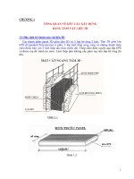
Fig.2a Section of Wooden pagodas
2. MODELLING OF FRICTION BEARINGS
According to [1], [2], [3], [4], [5] the central pillar directly supports on the stone footing, it can slide on surface of
the footing and isolated pagodas against earthquake by friction forces. The friction forces between the sliding
interfaces, on the other hand, plays a role of energy dissipating during the sliding motion. The motion of the friction
bearings can be solved into the following modes:
a. Stick mode: This occurs when the ground motion induced shear forces between the sliding interfaces of the
bearing fail to overcome the maximum friction force. In such occasions, the relative velocity between the
interfaces is zero.
b. Slide mode: When the ground motion induced shear force reaches the maximum friction force of sliding
interfaces, the bearing takes no more shear and is then forced to slide.
Under the assumption of small sliding displacement, the friction force acting along the sliding surfaces is governed
by
f £ mW (1)
Fig. 3a Model of the column and beam
We
Fig. 3b Model of the shinbashira on footing
Fig.2b Section of Wooden Pagoda (UEDA Atsushi, Ed.)
where m is the coefficient of friction. This coefficient is a constant as considered in Coulomb’s model, or dependent
on sliding velocity and the bearing pressure as proposed by Mokha and Constantinou for Teflon-steel interfaces as
. .
m = mmax –(mmax – mmin)exp(–a u1 u2
(2)
where mmax and mmin are, respectively, the maximum and the minimum values of the coefficient of friction, and the
coefficient a is to be determined from the bearing pressure, u1 – u2 is the relative displacement between the sliding
interfaces. The non-sliding conditions for the bearing are
..
f £ mW and u u2 = 0 (3)
1
..
And sliding occurs only if f mW sgn(u1 u2 ) (4), where sgn denotes the signum function.
Using the friction-pendulum isolators in SAP2000 program, this element can be used to model gap and friction
behavior between contacting surfaces. The response of a five-storied frame of timber pagoda subjected earthquakes
are considered. There are great differences between the response of time history for friction bearings and those for
fixed-base supports and hinge supports are investigated.
3. EQUATION OF MOTION FOR NONLINEAR DYNAMIC ANALYSIS
The equation of motion of a seismic-isolated pagoda structure under earthquake load w(t) can be represented as
.. .
M u(t ) + C u(t) + K u(t ) = B.F(t) + E.w(t)
Where u(t) is the n´1 displacement vector, M, C, K are, respectively, the n´n mass, damping and stiffness
matrices, E is the n´1 location matrix of the excitation load. B is the n´q location matrix of the friction forces and
F(t) is the q´1 friction vector with its satisfying the conditions described in equation (3) or (4).
4. NUMERICAL ANALYSIS
A five-storied frame of pagoda is considered in this study. According to Masaru Abe, the proportion of body width to
its total height is between the range of 4.5 - 6.5, the ratio of the height of sohrin to its total height is approximately
1/3 and the ratio of the roof width and body width is about 2.2, the slenderness ratio of the rafter (total cantilever
span of rafter/depth of rafter) is l < 16. Therefore, the frame has parameters, are considered.
Table I. Wooden member properties
Story height h = 4m The damping ratio 5%
Total height of shinbashira (central pillar) H = 30m Modulus elasticity of wood E = 107 kN/m2
Body width of frame B = 8m Coefficient of friction of wood m = 0.25
The ratio of the height of sohrin to total The gap between shinbashira and e = 3cm
height is approximately 1/3 D = 0.4m floors
Central pillar diameter d =0.3m Density of wood 12kN/m3
Others pillar diameter 0.25x0.4m The weight of roof q=10 kN/m
Rectangular beams and eaves Width of eaves 7m
Response to earthquake excitation
The response of a five-storied frame of timber pagoda by using the friction bearings can reduce the shear forces
resisted by the pillars that are most vulnerable during earthquake. The pillars can slide on footing surfaces, they
vibrate independently during the earthquake and thus interaction between them are minimized.
Table II. Effectiveness Assessment of seismic Isolation using Friction Bearings
Maximum response Types of timber pagoda
quantity*
Fixed –base Hinge supports Friction bearings isolation
a. El Centro
AP1 (kN) 554.6 428.5 73.75
AP2 (kN) 559 575.7 273
AP3 (kN) 599.8 448.2 73.74
MP1 (kNm) 86.09
MP2 (kNm) 232 0 0
MP3 (kNm) 86.55 0 0
VP1 (kN) 42.7 0 0
VP2 (kN) 104 20.79 2.299
VP3 (kN) 42.64 42.23 2.586
DB1 (cm) 22.48 1.8
DB2 (cm) 0 0 0.1495
DB3 (cm) 0 0 0.06162
DS (cm) 0 0 0.09044
18.75 20.42 6.176
b. Potrolia 812.8 653.2 88.43
AP1 (kN) 559.5 576.5 284.4
AP2 (kN) 694.2 661.5 119.4
AP3 (kN) 102.3
MP1 (kNm) 274.6 0 0
MP2 (kNm) 89.44 0 0
MP3 (kNm) 50.37 0 0
VP1 (kN) 122.8 45 10.31
VP2 (kN) 43.9 104.7 12.56
VP3 (kN) 51.83 4.663
DB1 (cm) 0 0 0.9613
DB2 (cm) 0 0 0.7645
DB3 (cm) 0 0 0.79098
DS (cm) 31.49 50.65 36.66
c. Loma Prieta 507.1 452 71.91
AP1 (kN) 558.9 576.5 272.4
AP2 (kN) 521.4 461.6 71.3
AP3 (kN)
MP1 (kNm) 57.05 0 0
MP2 (kNm) 167.6 0 0
MP3 (kNm) 65.94 0 0
VP1 (kN) 29.05 21.28 1.87
VP2 (kN) 74.8 40.59 1.4
VP3 (kN) 32.92 21.87 1.587
DB1 (cm) 0 0 0.116
DB2 (cm) 0 0 0.03065
DB3 (cm) 0 0 0.5979
DS (cm) 14.13 22.34 3.926
*AP1 = Axial of column C1, AP2 = Axial of column C2, AP3 = Axial of column C3, MP1 = Moment of column C1, MP2 =
Moment of column C2, MP3 = Moment of column C3, VP1 = Shear of column C1, VP2 = Shear of column C2, VP3 = Shear of
column C3, DB1 = Displacement of column C1, DB2 = Displacement of column C2, DB3 = Displacement of column C3, DS =
Displacement at sohrin.
Sohrin Sohrin Sohrin
C1 C2 C3 C1 C2 C3 C1 C2 C3
Friction bearings Fixed-base Hinge supports
Fig. 4 Analytical model for a five-storied timber pagoda
To show the effectiveness of seismic isolation, the axial, shear and moment at the column and displacement at the
friction bearings location, are examized. Simulations using the recorded earthquake ground motion of El Centro
(1940), Potrolia (1992) and LomaPrieta (1989) as inputs are presented.
a. El Centro earthquake (1940)
Simulation results are summarized in Table II.a. The responses of the fixed-base frames and hinge supports frame
are found to be very large during the time. When the friction bearings are constrained, the maximum shear forces
are reduced approximately from 94% at friction bearing 1 and 97% at friction bearing 2, the axial forces are reduced
from 51% at column 1 and 87% at column 3. The peak displacements at sohrin are reduced from 18.75 cm (fixed-
base) and 20.24 cm (hinge supports) to 6.176 cm (friction bearings). The maximum displacement of central pillar
(shinbashira) about 0.06162 cm, it very small, the shinbashira dissipates the energy of excitation by sliding, so the
pagoda is not collapsed during earthquake.
b. Potrolia earthquake (1992)
The scale of this earthquake is approximately two times of the 1940 El Centro earthquake in term of the resulted
peak structural responses of fixed-base, hinge supports while the maximum displacement at sohrin and shear forces
can be amplified five times (friction bearings model), as presented from Table II.b. However, the maximum
displacement at the friction bearings location is very small, and energy dissipation quickly by sliding. The isolation
by using friction bearings at the support show great performance in earthquake protection, as ilustrated in Table II.b
for the column’s base shear. The effectiveness of seismic isolation reduce base shear force from 80% at friction
bearing 1 and 89% at friction bearing 3. The axial at central pillar when using friction bearing reduce approximately
50% compare to fixed-base and hinge supports, this result can explain why the central pillar was hung during an
earthquake.
Fig.5a Response of displacement (El Centro earthquake) Fig.5b Response of displacement (Potrolia earthquake)
Displacement at sohrin (Friction bearings model) Displacement at sohrin (Friction bearings model)
Displacement at sohrin (Fixed-base model) Displacement at sohrin (Fixed-base model)
Displacement at sohrin (Hinge supports model) Displacement at sohrin (Hinge supports model)
c. Loma Prieta earthquake (1989)
Simulation results are summarized in Table II.c. The effectiveness of the isolation friction bearings and fixed-base
are reduced base shear forces about 90% in average, reduced axial forces about 50%. The base of column rarely
damage because shear force at column very small. Dynamic analysis of timber structure of pagoda indicate that the
sliding friction bearing is appropriate to reality structure.
Fig.6a Response of displacement (Loma Prieta earthquake) Fig.6b Response of displacement (Friction bearing model)
Displacement at sohrin (Friction bearings model) Displacement at friction bearing 2 (El centro)
Displacement at sohrin (Fixed-base model) Displacement at friction bearing 2 (Potrolia)
Displacement at sohrin (Hinge support model) Displacement at friction bearing 2 (Loma Prieta)
Effects of the coefficient of friction
The frames of pagoda are analysed when they are isolated for the coefficients of sliding friction from m = 0.1 ¸ 0.6.
The maximum displacements at the bearing location, axial force and shear force decrease slightly are presented, for
El Centro, Potrolia and Loma Prieta earthquakes (Fig.7a, 7b, 7c). The coefficient of friction is approximately 0.25¸0.35,
the response quantities have not changed very much, this result appropriate to the range of wood friction coefficient
(the coefficient of wood on wood m = 0.2 ¸ 0.5) .
Maximumdisplacement (cm) 0.4 DB1 Maximumdisplacement at the topcentral 30 El Centro earthquake
0.35 DB2 pillar (cm) 25 Potrolia earthquake
0.3 DB3 20 Loma Prieta earthquake
0.25 15
0.2 0.2 0.3 0.4 0.5 0.6 10 0.2 0.3 0.4 0.5 0.6
0.15 5
0.1 0
0.05
0.1
0
0.1
Coefficient of friction (Wood) Coefficient of friction (Wood)
El Centro earthquake
Fig. 7a Response of displacement at friction bearings Fig. 7d Response of displacement at sohrin
Maximumdisplacement (cm) 0.8 DB1 Axial forceat thebotomof central pillar (kN) 254 El Centro earthquake
0.7 DB2 252 Potrolia earthquake
0.6 DB3 250 Loma Prieta earthquake
0.5 248
0.4 0.2 0.3 0.4 0.5 0.6 246 0.2 0.3 0.4 0.5 0.6
0.3 244
0.2 242
0.1 240
238
0 236
0.1
0.1
Coefficient of friction (Wood) Coefficient of friction (Wood)
Potrolia earthquake
Fig. 7b Response of displacement at friction bearings Fig. 7e Response of axial force at friction bearings (VP2)
Maximumdisplacement (cm) 0.035 Shear force at the botomof central pillar (kN) 12 El Centro earthquake
0.03 10 Potrolia earthquake
0.025 8 Loma Prieta earthquake
0.02 6
0.015 0.2 0.3 0.4 0.5 DB1 4
0.01 DB2 2
0.005 DB3 0
0 0.6 0.1
0.1
0.2 0.3 0.4 0.5 0.6
Coefficient of friction (Wood) Coefficient of friction (Wood)
Loma Prieta earthquake
Fig. 7c Response of displacement at friction bearings Fig. 7f Response of shear force at friction bearing (AP2)
Effects of the gap between the central pillar and floors
Based on the conclusion of Masaru Abe, this paper is investigateed the gap between the shinbashira and each
floors, the gap changed from e = 1¸15 cm (Fig. 8a, 8b, 8c). The maximum displacements at the bearings location, and
at sohrin, the axial forces and shear forces at base columns have not changed very much in all cases. Therefore,
the appropriate gap is between the range from 3 to 5cm, the hole between the shinbashira and floors
prevent the pendulum movements from the main skeleton structure.
0.16 3.5
Maximum displacement (mm) 0.14 DB1
DB2
0.12 2.5
DB3
0.1 Normalized response quantities DS
0.08 DB1 AP2
0.06 DB2 1.5
VP2
0.04 DB3
0.02
0
1 3 5 7 9 11 13 15
Gap between central pillar and floor (cm) 0.5
El Centro earthquake 1 2 3 4 5 6
Effects of roof's weight
El Centro earthquake
Fig. 8a Effects of the gap between shinbashira and floors Fig. 9a Effects of roof’s weight b
1 3.5
0.9
0.8 3 DB1
0.7 Normalizedresponsequantities 2.5 DB2
Maximum displacement 0.6 DB1 DB3
(mm) 2
0.5 DB2
DS
0.4 DB3
1.5
0.3 AP2
0.2 1 VP2
0.1
0 0.5
1 3 5 7 9 11 13 15 1 2 3 4 5 6
Gap between central pillar and floor (cm) Effects of roof's weight
Potrolia earthquake Potrolia earthquake
Fig. 8b Effects of the gap between shinbashira and floors Fig. 9b Effects of roof’s weight b
0.1 3.5
3
Maximumdisplacement (mm) 0.08
2.5
0.06 DB1 Normalized response quantities 2 DB1
DB2 DB2
1.5 Db3
0.04 DB3 1 DS
AP
0.02 0.5 VP
1
0 6
1 3 5 7 9 11 13 15
Gap between central pillar and floor (cm) 2 3 4 5
Loma Prieta earthquake
Effects of roof's weight
Loma Prieta earthquake
Fig. 8c Effects of the gap between shinbashira and floors Fig. 9c Effects of roof’s weight b
Effects of roof’s weight
The unit weight of the roof considered in the analytical model is orginally 2.5 kN/m (0.25T/m), which corresponds to
light-weight. The effect of roof’s weight are investigated from light-weight to heavy-weight with weight ratio (b)
from 1¸ 6. The response quantities normalized with respect to those of the light-weight case b=1 are presented,
respectively, in Figure 9a, 9b, 9c for El Centro, Potrolia, and Loma Prieta earthquakes. The maximum
displacements at the bearings location (DB1, DB2, DB3) decrease slightly, while the peak displacement at sohrin,
axial force and shear force (AP, VP) increase with the roof’s weight, only slight variations in all the case. The
inertia forces of roof structures induced during earthquakes are almost transferred to the foundation. Therefore,
weight of roof effects a little to the responses of structure
5. CONCLUSIONS
The non-linear dynamic analysis of sliding structure has been proposed, based on reality structure and concept of
shear balance at sliding interfaces following a prescribed friction mechanism. The effectiveness of seismic isolation
by friction bearings reduce diplacement shear forces at the bearings, so the columns rarely damage under
earthquakes. The central pillar attached to the ground serves as a snubber, constraining each level from swinging
too far in any direction. The column and beam are not firmly connected, so each level can vibrates during an
earthquake, and the tapered configuration can endure strength and stability of timber pagodas. These features
combine to protect pagodas against earthquake. The basic principle of the flexible structure demonstrated by five-
storied pagodas in Japan is to let the building shake, thus dissipating the seismic force. This principle is now widely
used in modern highrises throughout the world, thus the wisdom of traditional architecture has become an essential
part of today’s state of the art building technology.
REFERENCES
1. Masaru Abe, Mamoru Kawaguchi, Structural Mechanism and Morphology of Timber Towers in Japan, Journal of
Asian Architecture and Building Engineering, November 2002, pp 25-32
2. The Economist print edition, Why pagodas don’t fall down, December 18th 1997, Kyoto
3. Unusual Mechanism, Five-storied Pagodas Resist Earthquakes by Quaking, Japanese Architecture.
4. Stephen Tobriner, Response of Traditional Wooden Japanese Construction, National Information Service for
Earthquake Engineering, University of California, Berkeley
5. Ahsan Kareem, Tracy Kijiewski, Yukio Tamura, Mitigation of Motions of Tall Buildings with Specific Examples of
recent Applications.
6. A.K.Chopra, 1995, Dynamics of Structures-Theory and Applications to Earthquake Engineering- Prentice Hall
International, Inc .
7. Hsiang-Chuan Tsai and James M.Kelly, 1993, Seismic Response of Heavily Damped Base Isolation Systems,
Earthquake Engineering and Structural Dynamics, Vol 22, pp 633-645.
8. R. Clough – W.J. Penzien, Dynamics of Structures, 1993, McGraw-Hill, Pubs. Co.
9. Tsung-Wulin and Chao-Chi-Hone, 1993, Base Isolation by Free Rolling Rods Under Basement, Earthquake
Engineering and Structural Dynamics, Vol 22, pp 261-273.
10. UEDA Atsushi, Spring 1995, The Riddle of Japan’s Quakeproof Pagodas, Japan Echo, Vol 22, No 1.
11. Yen-Po Wang, Lap-Loi Chung, Wei-Hsin Liao, 1998, Seismic Response Analysis of Bridges Isolated with
Friction Pendulum Bearings, Earthquake Engineering and Structural Dynamics, Vol 27, pp 1069-1093.