ARC WELDING pdf
Bạn đang xem bản rút gọn của tài liệu. Xem và tải ngay bản đầy đủ của tài liệu tại đây (31.35 MB, 330 trang )
ARC WELDING
Edited by Wladislav Sudnik
Arc Welding
Edited by Wladislav Sudnik
Published by InTech
Janeza Trdine 9, 51000 Rijeka, Croatia
Copyright © 2011 InTech
All chapters are Open Access distributed under the Creative Commons Attribution 3.0
license, which allows users to download, copy and build upon published articles even for
commercial purposes, as long as the author and publisher are properly credited, which
ensures maximum dissemination and a wider impact of our publications. After this work
has been published by InTech, authors have the right to republish it, in whole or part, in
any publication of which they are the author, and to make other personal use of the
work. Any republication, referencing or personal use of the work must explicitly identify
the original source.
As for readers, this license allows users to download, copy and build upon published
chapters even for commercial purposes, as long as the author and publisher are properly
credited, which ensures maximum dissemination and a wider impact of our publications.
Notice
Statements and opinions expressed in the chapters are these of the individual contributors
and not necessarily those of the editors or publisher. No responsibility is accepted for the
accuracy of information contained in the published chapters. The publisher assumes no
responsibility for any damage or injury to persons or property arising out of the use of any
materials, instructions, methods or ideas contained in the book.
Publishing Process Manager Marija Radja
Technical Editor Teodora Smiljanic
Cover Designer InTech Design Team
Image Copyright pmakin, 2011. DepositPhotos
First published December, 2011
Printed in Croatia
A free online edition of this book is available at www.intechopen.com
Additional hard copies can be obtained from
Arc Welding, Edited by Wladislav Sudnik
p. cm.
ISBN 978-953-307-642-3
free online editions of InTech
Books and Journals can be found at
www.intechopen.com
Contents
Preface IX
Part 1 Arc Welding Technology 1
Chapter 1 Hardfacing by Plasma Transferred Arc Process 3
Víctor Vergara Díaz, Jair Carlos Dutra
and Ana Sofia Climaco D'Oliveira
Chapter 2 Fusion Welding with Indirect Electric Arc 20
Rafael García, Víctor-Hugo López, Constantino Natividad,
Ricardo-Rafael Ambriz and Melchor Salazar
Part 2 Arc Welding Automation 45
Chapter 3 Arc Welding Automation 47
Eduardo José Lima II and Alexandre Queiroz Bracarense
Chapter 4 WHI Formula as
a New Criterion in Automatic Pipeline GMAW Process 71
Alireza Doodman Tipi and Fatemeh Sahraei
Chapter 5 Sensors for Quality Control in Welding 81
Sadek C. Absi Alfaro
Part 3 Weldability of Metals and Alloys 107
Chapter 6 Weldability of Iron Based Powder
Metal Alloys Using Pulsed GTAW Process 109
Edmilson Otoni Correa
Chapter 7 Assessment of Stress Corrosion
Cracking on Pipeline Steels
Weldments Used in the Petroleum
Industry by Slow Strain Rate Tests 127
A. Contreras, M. Salazar, A. Albiter, R. Galván and O. Vega
VI Contents
Chapter 8 Evaluation of the Shielding Gas Influence
on the Weldability of Ferritic Stainless Steel 151
Demostenes Ferreira Filho, Ruham Pablo Reis
and Valtair Antonio Ferraresi
Chapter 9 Corrosion Fatigue Behaviour
of Aluminium 5083-H111 Welded
Using Gas Metal Arc Welding Method 177
Kalenda Mutombo and Madeleine du Toit
Part 4 Mechanisms, Models,
and Measurements of Arc Welding 219
Chapter 10 The Mechanism of Undercut Formation
and High Speed Welding Technology 221
Zhenyang Lu and Pengfei Huang
Chapter 11 Physical Mechanisms and Mathematical Models
of Bead Defects Formation During Arc Welding 243
Wladislav Sudnik
Chapter 12 Using Solid State Calorimetry
for Measuring Gas Metal Arc Welding Efficiency 265
Stephan Egerland and Paul Colegrove
Chapter 13 Chemical and Physical Properties
of Fluxes for SAW of Low-Carbon Steels 281
Ana Ma. Paniagua-Mercado and Victor M. Lopez-Hirata
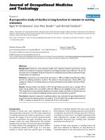
Chapter 14 Arc Welding Health Effects, Fume Formation
Mechanisms, and Characterization Methods 299
Matthew Gonser and Theodore Hogan
Preface
Ever since the invention of arc technology in 1870s and it's early use for welding lead
during the manufacture of lead-acid batteries, advances in arc welding throughout the
twentieth and twenty-first centuries have seen this form of processing applied to a
range of industries and progress to become one of the most effective techniques in
metals and alloys joining.
The objective of this book is to introduce relatively established methodologies and
techniques which have been studied, developed and applied in industries or
researches. State-of-the-art development aimed at improving technologies will be
presented covering topics such as weldability, technology, automation, modelling, and
measurement. This book also seeks to provide effective solutions to various
applications for engineers and researchers who are interested in arc material
processing.
This book is divided into 4 independent chapters corresponding to recent advances in
this field.
The editor expresses thankfulness to all authors for the presented materials and their
timely design, and also to the technical editor and to the book manager Mrs. Marija
Radja - for the big work on preparation and the edition of this book.
Editor
Prof. Dr. Wladislav Sudnik
R & E Center ‘Computer Hi-Tech in Materials Joining‘
Welding Department
Tula State University,
Russian Federation
Part 1
Arc Welding Technology
1
Hardfacing by Plasma Transferred
Arc Process
Víctor Vergara Díaz
1
, Jair Carlos Dutra
2
and Ana Sofia Climaco D'Oliveira
3
1
University of Antofagasta, Mechanical Engineering Department
2
University Federal de Santa Catarina, Mechanical Engineering Department
3
University Federal do Paraná, Mechanical Engineering Department
1
Chile
2,3
Brasil
1. Introduction
According to the literature, the plasma transferred arc welding process which employs the
filler metal in wire form is known as Plasma Arc Welding (PAW) while that which employs
powder filler material is generally referred to as Plasma Transferred Arc (PTA), Dai et al.,
2008.
The PTA process can be considered a derivation of the PAW process. The similarities
between the two processes can be observed in Figure 1. Both welding processes employ a
non-consumable tungsten electrode located inside the torch, a water-cooled constrictor
nozzle, shield gas for the protection of the molten pool, and the plasma gas. The difference
between the two welding processes lies in the nature of the filler material, powder instead of
wire, which requires a gas for its transport to the arc region. The diagram in Figure 1 shows
the two processes with their differences and similarities.
The equipment required to carry out the deposition through the PTA plasma process is very
similar to that used in PAW. When PAW is employed the equipment must be able to drive
spooled wires of various gages and different materials, at constant or pulsed velocities. In
the PTA plasma welding process, the filler material is used in the form of a powder, and
specific powder feeding equipment is required to transport it to the voltaic arc to produce
the coating. With respect to its application for coating, the PTA process is appropriate since
it produces dilution values of the order of 6 to 10 % (Gatto, et al., 2009), much lower than
those obtained with other arc soldering process which are around 20 to 25 %. The low
distortion, the small zone affected by the heat and the refined microstructure are also
features of this technique (Zhang, et al., 2008; Liu, et al., 2008).
In the PTA and PAW processes an inert gas is used as the plasma gas, which is forced to
pass through the orifice of the constrictor nozzle, where the electrode is concentrically fixed.
The shield gas passes through an external opening, concentric to the constrictor nozzle,
effectively protecting the weld against contamination from atmospheric air (active or inert).
On the other hand, in the PTA process a carrier gas is used to transport the filler material
through flexible tubes to the constrictor nozzle, allowing its entrance into the plasma arc in a
convergent form. The gas used for this purpose is generally argon.
Arc Welding
4
PAW PROCESSPTA PROCESS
Shield gas
Powder
Plasma arc
Plasma gas flow
Electrode
Substrate
Wire
Constrictor
nozzle
Fig. 1. Comparison of Plasma Transferred Arc processes PTA and PAW.
Given that the tungsten electrode lies within the constrictor nozzle of the welding torch, it is
difficult to open the arc by contact, and thus equipment called a plasma module must be
used to establish the arc opening. An electronic igniter provides voltage peaks between the
tungsten electrode and constrictor nozzle, generating a small spark in this region. Thus,
with the passage of the plasma gas a low intensity electric arc appears between the tungsten
electrode and constrictor nozzle, called the pilot arc (non-transferred arc). The pilot arc
forms a pathway of low electrical resistance between the tungsten electrode and the
workpiece to be welded facilitating the establishment of the main arc when a power source
is added.
In practice, the parameters which control the quality of the weld are the rate at which the
material is added, the gas flow rate (shield gas, plasma gas, carrier gas), the weld current,
the nozzle to workpiece distance (see below) and the welding speed.
The basic configuration of the constrictor nozzle is shown in Figure 2, where the parameters
employed in the process are indicated. The distance from the external face of the constrictor
nozzle to the substrate is called the nozzle to workpiece distance (NWD).
The recess (Rc) of the electrode is measured from the electrode tip to the external face of the
constrictor nozzle. Alterations in the arc characteristics are influenced by this factor, which
defines the degree of constriction and the rigidity of the plasma jet (Oliveira, 2001).
Oliveira (2001) studied the influence of the electrode recess of the plasma transferred arc
process fed by wire in order to identify whether the degree of arc constriction influences the
arc voltage. The results showed that, on average, a 2.4 V/mm variation in the voltage
occurred as a function of the electrode recess.
Hardfacing by Plasma Transferred Arc Process
5
Fig. 2. Nozzle to workpiece distance (NWD) and electrode setback (Rc) (Vergara, 2005).
In general, the maximum and minimum values for the adjustment of the electrode recess
vary according to the welding torch. The electrode recess of the welding torch PWM–300,
manufactured by Thermal Dynamics Corporation, for instance, has a range of adjustment of
0.8 to 2.4 mm.
As the electrode recess is reduced, the weld bead width increases and weld beads with
lower penetration depth are obtained. This variation in the geometric characteristics of the
weld bead is due to a reduction in the constriction effect producing a larger area of
incidence of the arc on the substrate.
The constrictor nozzle (made of copper), where the electrode is confined, has a central
orifice through which the arc and all of the plasma gas volume pass. The diameter of the
orifice of the constrictor nozzle has a great influence on the quality of the coating since this
relationship is directly related to the width and penetration of the weld bead produced. An
insufficient plasma gas flow rate affects the useful life of the constrictor nozzle since it leads
to its wear. The weld current reduces as a function of the decrease in the diameter of the
constricting orifice, due to an increase in the weld arc temperature.
The extent to which the nozzle to workpiece distance influences the coating is strongly
dependent on the electrode recess in relation to the constrictor nozzle and the diameter of
the constrictor orifice. The larger the electrode recess adopted and the smaller the
constrictor orifice diameter the greater the effect of the arc constriction, making it more
concentrated.
In the “melt–in” technique small electrode recess values are used, the arc being submitted to
a low degree of collimation, assuming a conical form. In this situation, a variation in the
nozzle to workpiece distance, even within normal limits, results in a change in the
characteristics of the weld bead, in the same way as occurs in the GTAW process. Thus, the
greater the nozzle to workpiece distance the lower the penetration and wider the width of
the weld bead due to the increase in the area of incidence of the arc on the substrate.
Arc Welding
6
Hallen et al. (1991) reported that to obtain a good deposition yield, the nozzle to workpiece
distance should not be greater than 10 to 15 mm. At values higher than this range the
efficiency of the shield gas is significantly reduced.
The authors of this paper have also reported results in relation to the nozzle to workpiece
distance, for two values: 15 and 20 mm. The study showed that as the nozzle to workpiece
distance increases the degree of dilution decreases.
The general objective of this study was to investigate the PAW and PTA welding processes
with a view to their application in surface coating operations, particularly on hydraulic
turbine blades worn by cavitation. This research was motivated by the observation that
information is scare in relation to the benefits offered by the plasma welding process using
powder instead of wire filler material in the application of coatings. The geometric
characteristics of the weld beads, degree of dilution, hardness and microstructure were
evaluated.
2. Materials and Methods
2.1 Test bench
Initially, a test bench was assembled based on equipment previously developed at
LABSOLDA (Oliveira, 2001; Vergara, 2005) which allowed tests to be carried out on the
plasma transferred arc welding process fed by wire. On the same test bench, a similar
process fed by powder was assembled. The welding source was equipment which, via an
interface, was connected to a PC. By way of a very versatile software program almost all of
the process variables could be controlled.
Of the three gas circuits, that which received most attention was the plasma gas given its
considerable relevance in terms of the quality of the deposits. A mass flow controller was
used, in which the control is carried out electronically and the command signal is a reference
voltage. The other gas flow circuits are simply monitored by electronic flow meters,
however these are volumetric.
One of the fundamental parts of the equipment is the device known as the plasma
module, which enables any version of plasma welding to be carried out based on
conventional welding sources for GTAW or coated electrode. For the displacement of the
welding torch an electronic device (Tartílope) was used. The system component which
was integrally designed for this specific development was the powder feeding device,
which functions through a combination of an endless screw and a gas flow as the powder
carrying mechanisms. The weld torch was developed based on the plasma torch for
keyhole welding. The great advantage of this lies in its multiprocess aspect which allows
it to work with plasma employing powder or with conventional plasma. Also, the design
adaptation allows the use of constrictor nozzles with different angles of convergence for
the powder feeding. Initially, analysis was carried out on the torches to be used in this
research. It was observed that the PTA torch had a nozzle with a constrictor diameter of
4.8 mm. In the case of the PAW torch, the manufacturer provides three nozzles with
constrictor diameters of 2.4, 2.8 and 3.2 mm, which are designed according to the welding
current to be applied.
In this case, the nozzle with the largest constrictor diameter available for the PAW torch was
selected, that is, 3.2 mm.
Figure 3 shows a general view of the equipment developed, that which forms part of the test
bench for the PAW and PTA welding processes being shown in the upper part of the figure.
Hardfacing by Plasma Transferred Arc Process
7
In this study argon with a purity of 99.99 % was used as the plasma, shield and carrier
gases. A tungsten electrode with 2% thorium oxide (EWTh-2) and with a diameter of 4.8
mm was used. The angle of the electrode tip was maintained at 30º for all of the
experiments.
Fig. 3. Test bench assembled at the welding laboratory. 1-Welding source; 2-Adapted
plasma torch; 3-Plasma module; 4-Powder feeder; 5-Torch displacement system; 6-Digital
gas meters; 7-Electronic gas valve; 8-Gases
2.2 Constrictor nozzle in PTA process
The configuration of the constrictor nozzle developed in this study included two conduits
for the passage of the carrier gas, the role of which is to feed the powder to the plasma arc in
a convergent form. Figure 4 shows a cross-section of the constrictor nozzle. At 60º the
constrictor nozzle allows the entrance of powder directly into the molten pool, when a
nozzle to workpiece distance of 10 mm is used.
Arc Welding
8
Fig. 4. Cross-section of constrictor nozzle showing the entrance of the powder flow into the
plasma arc. (Vergara, 2005).
2.3 Characterization
Deposits of the atomized alloy Stellite 6, Figure 5, were processed on carbon steel plates
(class ABNT 1020; dimensions 12.5 x 60 x 155 mm), using a constant continuous current.
Table 1 shows the chemical composition of the substrate. The chemical analysis of the
different filler materials was carried out by optical emission spectrometry and the results are
shown in Tables 2 and 3.
Single weld beads were deposited with the parameters indicated in Table 4 and samples
were removed for their characterization. This table gives the operational parameters for the
PTA and PAW plasma welding processes, in which there are parameters which could not
remain constant in the two process, for example: nature of the filler material (in PAW wire
and in PTA powder); wire speed (not required in PTA); carrier gas (not required in PAW);
constrictor nozzle diameter (in PTA 4.8 mm and in PAW 3.2 mm).
Initially, the weld beads were submitted to visual inspection for the presence of welding
defects, the degree of dilution was determined by the areas method using micrographs of
the cross-sections of the deposits, etched with 6% nital. Profiles of the Vickers
microhardness, with a load of 500g, enabled the evaluation of the uniformity of the weld
beads processed, according to the procedure of the standard ABNT6672/81. The
determination of the microhardness profiles, average of three measurements, was carried
out at the center of the weld beads and in the region where they overlap. To determine the
microstructure by optical microscopy a cross-section was prepared following standard
procedures, the microstructure being revealed after electrolytic attack with oxalic acid.
Hardfacing by Plasma Transferred Arc Process
9
Fig. 5. Morphology of powder deposited by the PTA process (Stellite 6).
C Si Mn P S Cr Mo Ni Al
0.11 0.22 0.74 0.021 0.008 0.027 0.024 0.011 0.06
Cu V W Sn Fe
0.016 0.015 0.026 0.065 98.6
Thickness: 12.7 mm
Table 1. Chemical composition of the low carbon steel substrate.
C Si Mn Cr Mo Ni Co W Fe
1.32 1.30 0.028 30.01 0.24 2.45 Bal 5.21 2.05
Hardness: 38-47 Rc; Particle size: 45 to 150 µm; Density: 8.3 g/cm
3
Table 2. Chemical composition of the filler material Stellite 6 in the form of a powder (BT-
906)
C Si Mn Cr Mo Ni Co W Fe
0.9-1.4 2.0 1.0 26-32 1.0 3.0 Bal 3.0-6.0 2.0
Table 3. Chemical composition of filler material Stellite 6 in the form of steel (BT-906T).
Arc Welding
10
PTA Process
Welding current
Welding speed
Plasma gas flow rate
Shield gas
Carrier gas
Feed rate
Constrictor nozzle diameter/ convergence
angle
Nozzle to workpiece distance
Setback
A
cm/min
l/min
l/min
l/min
kg/h
mm/º
mm
mm
160
20
2.2; 2.4; 3.0
10
2
1.4
4.8/30
10
2.4
PAW Process
Wire diameter (tubular)
Wire speed
Deposition rate
Constrictor nozzle diameter
mm
m/min
kg/h
mm
1.2
3.0
1.4
3.2
Welding current
Welding speed
Plasma gas flow rate
Shield gas
Feed rate
Nozzle to workpiece distance
Setback
A
cm/min
l/min
l/min
kg/h
mm
mm
160
20
2.2; 2.4; 3.0
10
1.4
10
2.4
Table 4. Welding variables and parameters.
3. Results and discussion
3.1 General characteristics
Figure 6 shows the external aspect of the beads where significant differences between them
can be observed. The PTA process produced a better surface finish, better dilution, better
wetting and wider width.
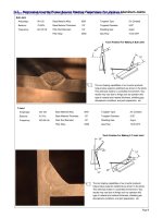
Figures 7 and 8 show cross-sections of the beads obtained using the two processes (PAW
and PTA) where considerable differences in the penetration profile of the welds can be
noted and Figure 9 shows the results for the geometric parameters of the beads, for the three
levels of plasma gas flow rate tested in this study: 2.2; 2.4 and 3.0 l/min. On comparing the
deposits obtained from the two processes it can be observed that the reinforcement and the
penetration are always smaller in the PTA process (Figure 9). In the PTA process there was
a significantly wider cord width, which is due to the use of a constrictor nozzle with a wider
diameter.
The data shown in Figure 9 together with an analysis of the variance in Tables 5, 6 and 7,
indicate that the welding process and plasma gas flow rate have significant effects on the
geometric parameters of the bead.
In relation to the convexity index (CI = 100*r/W), Silva et al. (2000) establishes that values
close to 30% are desirable for the relation between the width (W) and reinforcement (r) of
the weld bead. Figure 10 shows the convexity index of the weld bead for the PAW and PTA
processes as a function of the plasma gas flow rate.
Hardfacing by Plasma Transferred Arc Process
11
Analysis of Figure 10 shows that for the three plasma gas flow rates tested the PTA process
provided acceptable convexity of the weld beads (less than 30%), a highly desirable
condition. In the case of the PAW process, the convexity index was acceptable only for low
plasma gas flow rates.
The average values for the areas of the metal deposited varied for the two welding processes
studied, as expected, due to the difference in the diameters of the constriction orifices used
in each case and the material loss according to the efficiency of the deposition process.
Figure 11 shows that in the PTA process there was loss of material. Lin (1999) observed that
losses occur mainly due to vaporization and also dispersion of the particles after making
contact with the substrate.
Vergara (2005), reports that the carrier gas flow rate influences the dispersion of the
particles. In many cases it is possible, at the end of the finishing operation, to observe
unmolten powder particles adhered to the sides of the finish. On the other hand, when the
deposition rate is very high (1.5 kg/h) in relation to the welding current (160 A) unmolten
power can be seen spread over the substrate. Vergara [9] observed that the PTA process has
a deposition efficiency of the order of 87% when a constrictor nozzle of 30º is used. Similar
results have been reported by Davis (1993), who demonstrated a range of 85 to 95 %
deposition yield for the PTA process.
The graph in Figure 12 shows the effect of the plasma gas flow rate on the degree of dilution
using the wire Stellite 6, 1.2 mm tubular diameter. The results indicate that the dilution
increases with the plasma gas flow rate possibly due to the greater pressure of the plasma
jet. Similar results were found for the PTA process, with dilution values being lower than
those achieved with the PAW process, as expected, due to the difference in the diameters of
the constrictor orifice. Vergara (2005) reports that the diameter of the constrictor nozzle
orifice has a considerable influence on the quality of the finish since it is directly related to
the width and penetration of the weld bead produced. The data in Figure 12 together with
the analysis of variance in Table 8 indicate that, in general, the welding process and the
plasma gas flow rate significantly affect the dilution. Similar conclusions have been
reported by Silvério (2003) for the alloy Stellite 1.
The good results obtained for the PTA process are associated with:
Wider weld beads greater area of covering
Lower dilution deposits with composition closer to that of the filler alloy
Better wetting, lower convexity reduced risk of lack of penetration/ fusion between
weld beads.
a) PAW b) PTA
Fig. 6. Superficial aspect of Stellite 6 deposited by: a) PAW and b) PTA. Welding current =
160 A, Welding speed = 20 cm/min, Feed rate =1.4 kg/h, Plasma gas flow rate = 2.4 l/min.
Arc Welding
12
(a) (b)
(c)
Fig. 7. Cross-section of weld beads processed via PAW. Plasma gas flow rate: (a) 2.2 (l/min);
(b) 2.4 (l/min); and (c) 3.0 (l/min)
(a) (b)
Fig. 8. Cross-section of weld beads processed via PTA. Plasma gas flow rate: (a) 2.2 (l/min);
(b) 2.4 (l/min); and (c) 3.0 (l/min).
Hardfacing by Plasma Transferred Arc Process
13
8,4
8,2
7
9,4
9,9
9,6
0
2
4
6
8
10
12
Width (mm)
2,2 2,4 3,0 2,2 2,4 3,0
Plasma gas flow rate (l/min)
PAW
PTA
a) Width
2,4
3
2,8
1,66
2,12
1,86
0
2
4
6
8
10
12
Reinforcement (mm)
2,2 2,4 3,0 2,2 2,4 3,0
Plasma gas flow rate (l/min)
PAW
PTA
b) Reinforcement
1
1,7
1,4
0,12
0,19
0,2
0
2
4
6
8
10
12
Penetration (mm)
2,2 2,4 3,0 2,2 2,4 3,0
Plasma gas flow rate (l/min)
PAW
PTA
c) Penetration
Fig. 9. Effect of plasma gas flow rate on geometric parameters (Width, reinforcement,
penetration).
Arc Welding
14
28,6
36,6
40
17,7
21,4
19,4
0
5
10
15
20
25
30
35
40
45
IC (%)
2,2 2,4 3,0 2,2 2,4 3,0
Plasma gas flow rate (l/min)
PAW
PTA
Fig. 10. Effect of plasma gas flow rate on convexity index.
Source of variation
Sum of
squares
Degrees of
freedom
Average of
squares
F observed F critical
Welding process 17.85 1 17.85 1444.35
Plasma gas flow rate 2.316 2 1.16 93.67
Interaction 2.33 2 1.16 94.14 > 3.55
Residual 0.22 18 0.0124
Total 22.72 23
Obs.: Index of significance () = 5%
Table 5. Results of the analysis of variance for width.
Source of variation
Sum of
squares
Degrees of
freedom
Average of
squares
F observed F critical
Welding process 4.29 1 4.29 1353.78
Plasma gas flow rate 1.33 2 0.66 209.016
Interaction 0.098 2 0.049 15.45 > 3.55
Residual 0.057 18 0.0032
Total 5.77 23
Obs.: Index of significance () = 5%
Table 6. Results of analysis of variance for reinforcement.
Hardfacing by Plasma Transferred Arc Process
15
Source of variation
Sum of
squares
Degrees of
freedom
Average of
squares
F observed F critical
Welding process 8.35 1 8.354 5323.15
Plasma gas flow rate 0.58 2 0.288 183.74
Interaction 0.37 2 0.185 118.06 > 3.55
Residual 0.02825 18 0.00157
Total 9.33 23
Obs.: Index of significance () = 5%
Table 7. Results of analysis of variance for penetration.
23,6
25
21,4
12,6
16,5
15
0
5
10
15
20
25
30
Area of material deposited (mm
2
)
2,2 2,4 3,0 2,2 2,4 3,0
Plasma gas flow rate (l/min)
PAW
PTA
Fig. 11. Area of material deposited in PAW and PTA processes.
16,98
20,5
25,76
6,2
6,35
10,24
0
5
10
15
20
25
30
2,2 2,4 3,0
Dilution (%)
Plasma gas flow rate (l/min)
PAW
PTA
Fig. 12. Effect of plasma gas flow rate on degree of dilution in PAW and PTA processes.