WIND TUNNELS pdf
Bạn đang xem bản rút gọn của tài liệu. Xem và tải ngay bản đầy đủ của tài liệu tại đây (17.86 MB, 146 trang )
WIND TUNNELS
Edited by Satoru Okamoto
Wind Tunnels
Edited by Satoru Okamoto
Published by InTech
Janeza Trdine 9, 51000 Rijeka, Croatia
Copyright © 2011 InTech
All chapters are Open Access articles distributed under the Creative Commons
Non Commercial Share Alike Attribution 3.0 license, which permits to copy,
distribute, transmit, and adapt the work in any medium, so long as the original
work is properly cited. After this work has been published by InTech, authors
have the right to republish it, in whole or part, in any publication of which they
are the author, and to make other personal use of the work. Any republication,
referencing or personal use of the work must explicitly identify the original source.
Statements and opinions expressed in the chapters are these of the individual contributors
and not necessarily those of the editors or publisher. No responsibility is accepted
for the accuracy of information contained in the published articles. The publisher
assumes no responsibility for any damage or injury to persons or property arising out
of the use of any materials, instructions, methods or ideas contained in the book.
Publishing Process Manager Ivana Lorkovic
Technical Editor Teodora Smiljanic
Cover Designer Martina Sirotic
Image Copyright corepics, 2010. Used under license from Shutterstock.com
First published Februry, 2011
Printed in India
A free online edition of this book is available at www.intechopen.com
Additional hard copies can be obtained from
Wind Tunnels, Edited by Satoru Okamoto
p. cm.
ISBN 978-953-307-295-1
free online editions of InTech
Books and Journals can be found at
www.intechopen.com
Part 1
Chapter 1
Chapter 2
Chapter 3
Chapter 4
Part 2
Chapter 5
Chapter 6
Chapter 7
Preface VII
Wind Tunnel Technologies and Devices 1
Environmental Wind Tunnels 3
Jonathan Merrison
Dynamically Improved 6-DOF System for Measurements
of Forces and Torques in Wind Tunnels 23
V. Portman, B. Sandler and V. Chapsky
Stiffness Enhancement and Motion Control
of a 6-DOF Wire-driven Parallel Manipulator
with Redundant Actuations for Wind Tunnels 41
Xin Liu, Yuanying Qiu and Xuechao Duan
Rebuilding and Analysis of a SCIROCCO PWT
Test on a Large TPS Demonstrator 57
Sara Di Benedetto, Giuseppe C. Rufolo,
Marco Marini and Eduardo Trifoni
Applications of Wind Tunnels Testing 85
Flow Visualization and Proper Orthogonal
Decomposition of Aeroelastic Phenomena 87
Thomas Andrianne, Norizham Abdul Razak
and Grigorios Dimitriadis
Wind Tunnel Testing of Pneumatic Artificial
Muscles for Control Surface Actuation 105
Curt S. Kothera and Norman M. Wereley
Experimental Study of Flow-Induced Vibrations
and Scattering of Roof Tiles by Wind Tunnel Testing 121
Satoru Okamoto
Contents
Pref ac e
Wind tunnels are the primary research tools used in aerodynamic research. They are
used to study the eff ects of air moving past solid objects. Although great advances in
computational methods have been made in recent years, wind tunnel tests remain es-
sential for obtaining the full range of data required to guide detailed design decisions
for various practical engineering problems.
This book collects original and innovative research studies on recent applications in
wind tunnel tests, exhibiting various investigation directions and providing a bird’s
eye view on this broad subject area. It is composed of seven chapters that have been
grouped in two major parts. The fi rst part of the book (chapters 1–4) deals with wind
tunnel technologies and devices. The second part (chapters 5–7) deals with the latest
applications of wind tunnel testing.
The following is a brief description of the subjects that are covered in each chapter:
Chapter 1 reviews some examples of environmental wind tunnels.
Chapter 2 describes a 6-DOF system for the measurements of forces and torques in
wind tunnels.
Chapter 3 proposes a 6-DOF wire-driven parallel manipulator with redundant actua-
tions for wind tunnels.
Chapter 4 introduces the plasma wind tunnel test on a large thermal protection system
demonstrator.
Chapter 5 describes the fl ow visualization and the proper orthogonal decomposition
of aeroelastic phenomena.
Chapter 6 introduces the wind tunnel testing of pneumatic artifi cial muscles.
Chapter 7 provides the fl ow-induced vibrations and sca ering of roof tiles by wind
tunnel testing.
The text is addressed not only to researchers but also to professional engineers, engi-
neering lecturers, and students seeking to gain be er understanding of the current
status of wind tunnels.
Through its seven chapters, the reader will have an access to a wide range of works
related to wind tunnel testing.
VIII
Preface
I am extremely honored to be editing such a valuable book, which contains contribu-
tions of a selected group of researchers describing the best of their work. I would like to
express my sincere gratitude to all of them for their outstanding chapters.
I also wish to acknowledge the InTech editorial staff , in particular Ms. Ivana Lorković,
for indispensable technical assistance in book preparation and publishing.
Prof. Satoru Okamoto
Department of Mathematics and Computer Science
Shimane University
Matsue Japan
Part 1
Wind Tunnel Technologies and Devices
1
Environmental Wind Tunnels
Jonathan Merrison
Aarhus University,
Denmark
1. Introduction
Wind tunnels have been used extensively in industry and research applications over the
past 50 years. They vary greatly in scale and geometry, with some large enough to house
and test small aircraft (see for example NASA, ATP facilities) and others are miniaturized
flow generators used in the calibration of small sensors. However they invariably utilize the
same basic technology and design elements. Similarly environmental simulators are also
used widely in research, for example in climate and planetary studies. Here again they
superficially vary greatly in size and configuration, but basically consist of a hermetic
chamber with some form of temperature control [Jensen et al. 2008]. There is therefore a
broad array of standard and often commercial technologies and construction techniques
which have been successfully applied within the fields of wind tunnel and environmental
simulator design. Some of these technologies and techniques will be outlined in this chapter
to aid researchers or technology developers in their efforts to design or use environmental
wind tunnels and also serve as an informative guide to those new to these fields of
investigation.
The fusion of an environmental simulator and a wind tunnel is a natural evolution of
laboratory based technology to fulfill the need to reproduce specific physical conditions
found in nature. Although facilities of this kind are only now being fully developed, they
have the potential to expand into a new research field that could substantially contribute to
our understanding of climate and mediate growth in advanced sensor technologies. In this
chapter many of the challenges in designing and constructing environmental wind tunnels
will be introduced and possible solutions presented, with some emphasis placed on extreme
terrestrial and Martian planetary conditions. In addition some of the many and varied
scientific and industrial applications will be discussed. Generally environmental wind
tunnels are already in current use as a method of testing and calibrating meteorology
sensors of various kinds especially wind flow sensors (anemometers). Application of wind
tunnels in civil engineering and town planning is becoming common place. Here through
wind tunnel simulation and modeling the flow of air around buildings and through built-up
areas may be useful to avoid the generation of high wind shear and hazardous vortices at
periods of high wind or storms. Such simulations can also aid in the design and placement
of wind generation systems such as wind turbines.
The formalized scaling laws developed by Reynolds (Reynolds equations) allows
measurements, for example in smaller scale laboratory wind tunnels, which generate the
same (or extremely similar) flow to that generated in the natural setting [Monin and Yaglom
Wind Tunnels
4
1973, Hall 1988, Mollinger and Nieuwstadt 1996, Fay and Sonwalkar 1991]. This scaling law
involves the relationship between wind speed, spatial scale and viscosity such that adjusting
and combining these parameters can allow realistic laboratory simulation for example on
the cm-m scale of flow dynamics on the 10s to 100s of meters. It can also, for example, allow
comparison of effects in one fluid (e.g. air) to be translated into those seen in another fluid
such as water. This technique has been successfully applied in the design of all forms of
transport, such as aircraft, ships and cars.
Wind tunnel studies have and are contributing powerfully in attempts to understand and
describe the action of wind in arid areas. Following the pioneering work of Bagnold, including
the use of laboratory (and field) wind tunnels, the study of Aeolian (wind driven) sand
transport has evolved into a scientific research field [Bagnold 1941]. It is now clear that
Aeolian transport has a great impact on local environments and on the global climate through
the production of aerosols, the erosion of surface material and the serious environmental
problem of desertification. Aeolian transport of sand/dust under planetary conditions other
than Earths is also of great importance to understanding these extreme environments and can
help achieve a deeper understanding of our own environment. For example Aeolian processes
are seen on Mars, Venus and Saturn’s moon Titan, but are probably found on any planetary
body with a significant atmosphere. Sand features such as dunes are common on these planets
and in the case of Mars dust entrainment is seen to be the most powerful climatic factor.
Interesting differences in the Aeolian features seen in these extra-terrestrial environments is
the spatial scale compared to those on Earth. The study of extra terrestrial Aeolian phenomena
can only effectively be studied in the laboratory using an environmental wind tunnel
simulator. Even with such simulators, only some aspects of Aeolian transport on other planets
can be successfully reproduced, such as the surface shear stress, wind speed, fluid density,
temperature, humidity and (more ambitiously) surface microstructure, adhesive properties.
Other physical aspects are extremely problematic, for example gravity and specifics of the
surface composition (mineralogy).
An obvious application for an environmental wind tunnel is the study of the upper
atmosphere (the troposphere and stratosphere), specifically low temperatures, low
pressures and the presence of aerosols of various types. Clearly this is of relevance to the
aircraft industry, especially (high altitude) jet aircraft. The recent (2010) disturbance in
Atlantic flights due to the generation of dust aerosols by the Icelandic volcano
(Eyjafjallajökull) is a good example, where a deeper understanding of these aerosols in the
upper atmosphere could possibly have avoided a large degree of disruption. The
development of new aerosol sensor technologies also appears to be necessary. In fact wind
tunnels can both help to unravel the complex dynamics of aerosol behavior and to
understand their formation processes through the generation of fine suspended mineral
particulates (dust). It should be stressed here that the study of aerosols is far from being
limited to a global climatic factor. Aerosols present a real hazard to environmental and
human safety both in the home and in local environments. Conversely aerosols are also used
widely in medicine and the pharmaceutical and cosmetics industries. Specifically nano-
micro meter scale particulates suspended in the air can penetrate the deep lung as well as be
suspended for long periods of time (months) in the atmosphere and transported great
distances (globally). Smoke, clouds, dust, are just some of the many forms of aerosol that
affect our environment and can be studied in environmental wind tunnels to better
understand their (apparently complex) behavior as well as develop new technology in order
to quantify and control them.
Environmental Wind Tunnels
5
Fig. 1. Left upper and lower; satellite photographs of Mars and Earth, North Africa
respectively, showing dust storms and clouds. (Courtesy NASA/JPL-Caltech). Right upper
fog in Mars, Valles Marineris taken by the High Resolution Stereo Camera (HRSC) on board
ESA’s Mars Express spacecraft, Right lower; acid haze seen amongst the thick clouds of
Venus, photographed by the ESA's Venus Express spacecraft.
In the future the study of aerosols will probably be the single most important application of
environmental wind tunnels and it is hoped that the work presented here will contribute
towards these types of study.
2. Environmental wind tunnel mechanical design
There are two basic types of wind tunnel design which may be referred to as Open Circuit
or Closed Circuit (or closed cycle). In a terrestrial (ambient pressure) open circuit wind
tunnel design fresh air is drawn (or blown) into the entrance and expelled at the exit,
whereas in a closed circuit wind tunnel the expelled air is fed again into the inlet such that
the same air is re-circulated. Either of these two wind tunnel types can be housed in an
environmental (or planetary simulation) chamber giving rise to two distinct types of
environmental wind tunnel design. These different wind tunnel types (shown schematically
in figures 2a-2d) have distinct characteristics, their advantages and disadvantages will be
discussed.
The implementation of thermal and flow control within these differing system designs will
vary. In the case of the open circuit design flow and thermal control systems should be
implemented upwind and focus primarily on manipulating the gas which is inlet. In the
case of a re-circulating design, since the system is a closed cycle, flow correction and thermal
control can in principle be implemented in any (or all) sections of the circuit. In practice the
Wind Tunnels
6
implementation of thermal control will depend on the thermal control system chosen and
general technical restraints of the wind tunnel design. Similarly flow control will depend on
the desired flow characteristics and the practical limitations on resources.
Figure 2a Open Circuit
Ambient Pressure
Figure 2b Open Circuit
Enclosed (Pressure/Vacuum
Chamber)
Figure 2c Closed Circuit
Enclosed (Ambient Pressure)
Figure 2d Closed Circuit
Enclosed (Pressure/Vacuum
Chamber)
Fig. 2. Different types of Wind Tunnel geometry combining open/closed circuit designs and
ambient or enclosed (environmental control).
In traditional ambient pressure wind tunnel facilities the choice of construction materials is
largely unrestricted. Materials are therefore chosen dependent on mechanical properties
(strength, weight, etc.) and possibly also cost and availability, wood for example is used in
many wind tunnels. For environmental wind tunnels the choice of materials is generally far
more restrictive since, to maintain low pressure or gas purity, materials with low out-
gassing properties should be chosen and for temperature control the thermal properties and
mechanical properties at low temperatures must be considered. The choice of materials
subsequently affects the mechanical design of the wind tunnel structure.
External access to the wind tunnel (especially the test section) is also of great importance in
most cases, both during operation and installation or maintenance. Here access includes, for
Environmental Wind Tunnels
7
Fig. 3. Schematics of Left; Aarhus University Wind Tunnel I (AWTSI) design, Center; AWTS
II design, Right; open circuit ambient showing upwind flow control (see flow control)
example mechanical, electrical and optical (visual) systems. Specifically mechanical access
could involve being able to orientate a sample or sensor and therefore require rotation or
translation mechanisms. Electrical access may be in the form of cabling for power and data
transfer. Optical access could be cameras, lighting, spectrometers or other optical sensors.
Ideally these forms of access should be as spatially close to the active section of the wind
tunnel as possible and preferably large in cross section. For ideal flow (i.e. minimizing
boundary effects) a wind tunnel should be cylindrical in cross section, however for the
housing and access of samples/sensors, as well as many other practical applications of wind
tunnels, it is desirable to use a rectangular cross section. This does not constitute a problem
for most ambient-pressure applications; however for an enclosed (pressurized) wind tunnel
this does present a technical challenge. The two environmental wind tunnel systems at
Aarhus University apply two radically different geometrical solutions to this problem, with
the AWTS-I system housing the cylindrical wind tunnel within its own (cylindrical) return
flow, giving a rather attractive flow transport and uniform cross-section, though poor access
to the test section and a non-optimal (circular) cross-section [Merrison et al. 2008]. The
AWTS-II design conversely has an attractive, almost rectangular wind tunnel cross-section
and good access to the test section, however the return flow is divided into two, above and
below the test section, giving extremely non-ideal flow and constriction of the flow in the
return section, which resulted in the need for extensive flow correction. At low pressure
(below 100mbar) the highest wind speed achieved by AWTSI is around 15-20m/s, whereas
AWTSII has achieved 20-25m/s, with similar degrees of (free flow) turbulence for both wind
tunnels i.e. 5-20% increasing with wind speed.
Fig. 4. Photographs of the (10m long) AWTS-II facility showing the mobile environmental
chamber sections, the central test section can be removed laterally.
In contrast to the Aarhus environmental wind tunnels the NASA Ames MARSWIT (Mars
Surface Wind Tunnel, California USA) is an open-circuit, low pressure wind tunnel
powered by a high pressure nozzle ejector system, the total length is 13m with a main test
section of 1.2m by 0.9 m and is housed in a 4000 m
3
low-pressure chamber which can
operate at pressures down to ~3.8 mbar and wind speeds of 20m/s - 180m/s (at low
Wind Tunnels
8
pressure) [White 1981, Greeley and Iversen 1985]. This system cannot be cooled and has
been used for boundary layer studies.
For low pressure wind tunnel systems the structure of the vacuum chamber is one of the
primary design features. This will typically require the use of a thick (bulky) steel shell and
frame which, for mechanical strength, will optimally be cylindrical/spherical in form. This
is similarly true for high pressure vessels. For open circuit environmental wind tunnels the
limitations on the pressure vessel will limit the size and geometry of the test section.
However for a re-circulating environmental wind tunnel the pressure vessel will even more
strongly restrict design of the wind tunnel since, assuming the largest free flow cross section
is desired then there must still be sufficient space for the return flow to be housed. It is
desirable for this return flow cross section to be comparable to the test section cross section
to avoid high turbulence and turbulent losses. The AWTS-II facility is one of the largest
environmental wind tunnels with a cross section of around 2m×1m and a chamber volume
of around 40m
3
, it is significantly larger than the almost 1m
3
volume and cross section of
0.4m×0.4m of the AWTS-I.
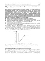
Fig. 5. A Light Emitting Diode based light source for solar simulation, illumination or crude
spectroscopy in an environmental wind tunnel. Upper Left shows a photograph of a single
array section including one of each of the seven different (wavelength) LEDs, Upper Right
shows the irradiance measured within the wind tunnel (with all LEDs activated) showing
the single wavelength components, the Lower photographs are taken inside the wind tunnel
test section as different colored LED arrays are activated (red, green blue), the LED array
strips are mounted in the upper two edges of this section.
In both industrial and scientific applications a common requirement is a light source which
simulates the solar irradiance over a broad wavelength range. A problem with many light
sources, for example halogen lamps and discharge lamps, is the generation of heat, both
conductive and as thermal radiation (infra-red) which can make environmental temperature
control difficult. Employing a light source outside the environmental chamber alleviates this
0
0,02
0,04
0,06
0,08
0,1
0,12
0,14
350 400 450 500 550 600 650 700 750 800
Intensity W/m
2
/nm
Wavelength nm
Environmental Wind Tunnels
9
problem, however it then restricts the illumination of samples considerably. Compromise
here will generally be necessary. An attractive option is the use of light emitting diodes
(LEDs) which are efficient and monochromatic, being available as intense sources though
generating relatively little heat. LEDs are low voltage making them technically easy to
implement in most cases. With the use of arrays of variously colored LED the correct light
irradiance can be achieved within broad optical wavelengths and even into the near infra-
red (more than 1000nm) and the Ultra Violet, with the latest UV LEDs below 250nm.
3. Flow control
Wind tunnels vary in their requirements for flow uniformity, while some are designed for
low turbulence (close to laminar) flow, others apply techniques in order to reproduce
particular boundary layer conditions (often referred to as boundary layer wind tunnels)
whereas for some a specific free-flow degree of turbulence is required. In these differing
cases it is probably fair to say that they are attempting to reproduce differing turbulence
regimes present in nature and that it is therefore difficult to generalize about these wind
flow designs. However it is worth discussing differing flow control techniques which are
commonly employed and how specifically they can be applied.
Flow guides are smooth plates of differing geometry which are installed in order to steer the
wind flow to obtain a desired wind pattern. For example they may be; curved in order to
guide the flow around bends, they may be planar in order to straighten the flow or they may
be used to partition the flow into sections in order to prevent unwanted lateral flow/eddies.
In open circuit wind tunnels flow control should (obviously) be installed upwind. However,
in a re-circulating wind tunnel they should generally be installed at the source of the
unwanted flow pattern, which could be upwind or down wind. In the case of the European
Mars Environmental Wind Tunnel (see figure 6) flow guides have been used to great effect
at the entrance to the wind generating fans system and prevented extremely destructive
back-flow caused by the rotation of the fan blades. Meshes are used to reduce turbulence in
the wind flow and to obtain a more homogeneous flow profile, especially on scales larger
than the mesh size which is typically of the order of 1mm. This is done at the expense of
wind speed. Meshes are often utilized as a set of two separated by some mm-cm. In this case
a pressure gradient is generated across the meshes, this helps to disrupt turbulence and non-
uniformities in the flow. It should be noted that both flow guides and meshes while
improving flow properties, will typically increase friction and therefore reduce the (net)
wind flow for a particular wind generation power. The use of upwind roughness blocks and
turbulence spires manipulate the vertical wind flow profile (at the test section) in order to
emulate an infinite upwind ‘fetch’ i.e. to reproduce the surface boundary layer flow which
would be produced if the wind tunnel were infinite in length. Clearly this is of great
importance when studying boundary layer effects such as the entrainment and transport of
sand or the flow patterns around a surface feature [Irwin 1981, Shao and Raupach 1992].
Expansion and compression stages can be used in wind tunnel design to increase wind
speed, improve flow linearity and reduce turbulence. Here compression of the wind tunnel
will increase the downwind flow speed and reduce the relative transverse turbulence.
Clearly this is done at the cost of wind tunnel cross-sectional size and is not always possible
to implement especially within a re-circulating wind tunnel. Often in open circuit wind
tunnels and invariably in re-circulating systems wind generation is provided by a fan or
fans. Fan design is in many cases non trivial, involving modeling and calculation regarding
Wind Tunnels
10
the specific choice of fan blade size, number, form, angle and also motor power, torque and
rotation rate. Such modeling and calculation can be aided by computational fluid dynamic
calculations. Here one begins with the required parameters of wind speed (and ambient
pressure), based on the wind tunnel design. The flow calculations will then predict a certain
degree of frictional loss as a function of wind speed. The fan system can then be modeled as
a system to generate a pressure gradient necessary to balance this frictional loss and
maintain the desired flow rate. Given the flow rate and the required pressure differential a
particular fan design can be chosen i.e. these are the required input parameters for the
choice of fan design. In the case of environmental wind tunnels the choice of fan material
must also be considered, for example to be compatible with out-gassing limits and low/high
temperature.
Fig. 6. Photographs into the flow generation section at the AWTS-II facility, Left shows the
1.8m diameter fans installed, Center shows with the upper and lower flow separators and
Right the system of vertical and horizontal flow guides compartmentalizing the flow,
preventing rotation and excessive turbulence.
Since almost all forms of high power motor are incompatible with the demands of (low)
pressure and temperature within an environmental chamber, the drive mechanism for a fan
system must be mounted externally. This presents a problem for the transfer of torque to the
fan since passing a rapidly rotating axel through a pressure seal system is also incompatible
with avoiding pressure leaks and maintaining low temperatures. A possible solution which
has been employed in the various facilities at Aarhus University is the use of a magnetic
coupling [Merrison et al. 2008]. Such couplings are commercially available and transfer
torque from the drive axel (external) to the fan axel (internal) through a complex of magnetic
fields generated by permanent magnets. This avoids physical contact of the two axels and
allows this coupling to be completely hermetic (vacuum tight). A drawback with this system
is the limited degree of torque which can be transferred by such couplings before they begin
to slip which may limit the rotation rate (wind speed) within the wind tunnel. It does
however have the benefit of protecting the drive-fan system from damage as slippage of this
coupling is not hazardous.
A type of open circuit environmental chamber has been employed for Mars simulation
conditions at Oxford University. Here gas is injected from an array of (relatively small)
inlets into a flow volume which is continually being evacuated by a pump. In this case an
extremely low turbulence flow can be achieved along with high flow speeds as well as
cooling. A drawback can be that the flow rate is dependent upon the chamber pressure such
that control of low flow speed involves inlet and pump rate control. Such a system can be
well suited to anemometer calibration and high wind speed tests [Wilson et al. 2008].
Discussion here has focused on low wind speeds (subsonic flows). There are however, forms
of wind tunnel which generate and utilize supersonic and even hyper sonic flows for
various studies. Specific applications are in the design and testing of supersonic aircraft or
Environmental Wind Tunnels
11
re-entry devices. It should be noted that such wind tunnels utilize specialized techniques
and the flow in such high velocity regimes differs from that at wind speeds significantly
below that of sound [Barlow 1999]. Generally environmental wind tunnels will involve
compromising the ‘ideal’ wind flow characteristics due to geometric constraints imposed by
the environmental chamber or environmental control systems, for example reduced cross
section, increased turbulence, reduced maximum wind speed or the use of cumbersome
flow control systems.
Fig. 7. Computational Fluid Dynamic calculations of an object within a wind tunnel
showing: Upper; the finite element structure, Center; the calculated wind speed flow from
red (high) to blue (low)and Lower; suspended (aerosol) particulates added to the flow and
their trajectories traced.
4. Computational fluid dynamics
This chapter has focused upon experimental/laboratory studies using environmental wind
tunnels, however discussion should be made of the use of computational fluid dynamic
modeling in this regard as in some cases this may be an alternative to laboratory simulation.
However in most cases these two techniques are complementary. When constructing a fluid
dynamic model in order to perform computational flow analysis it is necessary to make
simplifications and assumptions which in most cases must be verified experimentally in
order for confidence to be placed on the results [Peric et al. 1999]. A specific example is the
calculation of flow around an irregular shaped object. In this case it is necessary to construct
a finite element representation of this geometry before inputting wind flow boundary
conditions. Although the resolution of this finite element array can be increased in order to
Wind Tunnels
12
ascertain convergence, this will also be limited by computing power. Here comparison with
experiment can be of great benefit in identifying sources of high sensitivity in the flow such
that resolution be enhanced in this volume (see figure 7). A combination of targeted
laboratory measurements and computational analysis can be ideal in simulating complex
and difficult flow problems [Kinch et al. 2005]. Typically CFD is employed in the design
phase of wind tunnels, though often the flow is complex and multi-dimensional such that
empirical measurement and the implementation of correction elements is necessary to arrive
at the most satisfactory flow characteristics.
5. Environmental sensing technology
A crucial aspect to any application of wind tunnels and/or environmental simulators is the
use of accurate and reliable sensor systems for control and reproducibility of the simulated
conditions. Some sensor systems are readily and commercially available at a well evolved
level, for example for temperature and pressure. Other sensor systems can be complex,
expensive and require adaptation, examples are wind sensors (anemometers) and gas
composition. For some sensor systems there is a clear demand for new technology, yet this
technology awaits development, examples are shear stress sensing and aerosol analysis.
In temperature sensing thermo-resistors are widely available (for example 100 Ohm
platinum resistors i.e. Pt100), these are typically inexpensive and are accurate (typically
around 1°C) over a wide range. The same could also be said of thermocouples (e.g. K-type),
though these generally have a limited low temperature range. Thermocouples can also be
difficult to integrate into an environmental chamber due to the need to maintain the contact
potential i.e. maintain the exotic metal cables. Pressure sensor systems are available either
for high pressure use, low pressures or specific to terrestrial conditions, i.e. limited to
around 1 bar. Low pressure sensors are typically (generically) referred to as vacuum gauges.
A type of vacuum gauge which is ideal for moderate low pressures (down to say 0.1mbar)
and which is accurate even in differing gas compositions is the capacitance vacuum sensor,
it is therefore well suited to study of Earth’s upper atmosphere or Mars. Such capacitor
based techniques are also useful for determining pressure differentials which can be
important in wind tunnel design or wind sensing (see Pitot tube). Although absolute
humidity (water vapor pressure) sensors are typically complex and expensive, relative
humidity sensors are often extremely compact and operate over wide temperature and
pressure ranges. Specifically thin polymer film type sensors are commercially available and
are easily implemented into an environmental system (e.g. Honeywell HIH series).
In environmental systems where the atmospheric composition may be controlled it is
important to be able to monitor it. There are few available options in this case and typically a
sensor system called a Rest Gas Analyzer is used. These are often a type of quadrapole (radio
frequency) mass spectrometer. They operate by ionizing the gas at low pressure (i.e. leaked
through a valve) and extracting the ion fragments individually to determine their mass to
charge ratio. It may then be possible to re-construct the original molecular structure of the gas,
it is however difficult if the atmosphere contains several species where some fragments are
ambiguous and it is often difficult to precisely determine abundances without careful
control/calibration of the system and some expertise. Although these systems are relatively
expensive and cumbersome to install, there is at present a lack of viable alternatives.
Finally in any application where an array of sensory systems is used, it is desirable to
implement a data-logging system which records the various sensor outputs during
Environmental Wind Tunnels
13
measurement cycles. For environmental wind tunnel systems it is also natural then to
integrate this data logging capability into a computer system which also interfaces (and
records) some of the control parameters of the facility such as wind generation (driving fan
rotation rate), vacuum/pressure control system (pumps, valves etc,), cooling/heating
systems or lighting subsystems. Although this constitutes an added level of complexity it
allows for a higher level of reproducibility, sensor correlation and possibly safety.
6. Flow sensing technology
Clearly of primary importance with regard to wind tunnels is the accurate sensing of wind
flow (Anemometry). There is a wide variety of available anemometer techniques, some
dating back over 500 years, others are still being developed. These wind sensing systems
vary in accuracy, complexity, price, size, and so on. In the following paragraphs some of the
most common wind sensing technologies will be presented and briefly discussed,
specifically with respect to their application in wind tunnels.
Fig. 8. Photographs of Laser Anemometers (acting also as suspended dust sensors), Left
prototype time of flight instrument, Center the sensor during aerosol testing in an
environmental wind tunnel, Right A commercial Laser Doppler Anemometer operating
through an environmental wind tunnel access window, note the beams illuminating the
suspended dust in the flow.
6.1 Laser anemometers
These are probably the most advanced and desirable type of wind sensor which have been
applied in wind tunnels, specifically the Laser Doppler Anemometer (LDA) is used
extensively. Several more recent variations on this instrument can measure in multiple
dimensions, image and determine suspended grain size. This technique has the benefit of
being non contact, such that it is independent of the environmental conditions within the
flow (pressure, temperature, composition, etc.), it is also accurate and does not normally
require external calibration. In fact LDA based systems are widely used in wind tunnel
applications for the calibration of other types of wind sensor. The principle behind the
technique is the scattering and detection of light by suspended aerosol particles, by
measuring the frequency shift due to the velocity induced Doppler effect. More specifically
two (or more) beams are use to produce an interference pattern, measurement of the shift in
this pattern allows single velocity components of the grains to be determined. The system
does have the disadvantage of requiring the presence of suspended particulates within the
flow, which are introduced as smoke in many systems. However, for systems studying
aerosols this is a major advantage since the suspended grain concentration can be quantified
using this technique. Typically LDA systems are expensive and bulky, though can use
Wind Tunnels
14
optical fibers and therefore achieve a relatively compact sensing head. Miniature (even
micro-scale) laser based wind sensors are being developed, though have yet to advance
from prototyping. One such system is based on a time of flight principle in which a light
pattern is generated within the sensing volume. Single suspended aerosol particulates
traversing this light pattern will scatter light with a modulated signal from which its
velocity can be established, specifically in the case of the prototype shown in figure 8 a three
line light pattern is used and the scattered light signal will consist of three pulses the time
separation is then directly related to the velocity [Merrison et al. 2004, Merrison et al. 2006].
This type of technology has the potential to become miniaturized (on the sub-cm scale) and
have low power consumption as well as being robust. Although limited in precision
compared to LDA systems, it may be applied in systems too small or inaccessible for larger
sensors and provide an affordable (and portable/battery driven) aerosol sensor. The current
advancements in solid state laser and other optoelectronic technology give sensors of this
kind a promising future.
6.2 Mechanical (cup anemometers or wind socks)
Mechanical anemometers are by the far the oldest, simplest, most common and varied form
of wind sensor. Most widely used are cup anemometers and forms of wind sock or wind
vane. A cup anemometer consists typically of conical cups mounted on a axel such that
wind drag causes rotational motion which can be sensed by a tachometer in order to relate
the rotation rate to the wind speed. Wind vanes and socks are typically more primitive and
consist of a structure (tube/sock or plate) which is deflected by the wind such that the
deflection angle is a measure of the wind speed and the direction may often be seen in the
direction of the deflection. Such mechanical wind sensors are rarely used in wind tunnel
applications due to their poor accuracy/precision and often limited dynamic range. They
are however an invariable component of weather/climatic stations on Earth and have even
been adapted for the extreme environment of Mars and Venus. Such systems can potentially
be extremely compact, light weight, sensitive and robust given careful design and testing
[Gunnlaugsson et al. 2008].
6.3 Hot wire or hot film
These sensors have been used extensively in wind tunnel experiments over several decades.
They are typically accurate and sensitive in terrestrial conditions, they can also be multi
dimensional and have reasonably fast response times. Compared to mechanical wind
sensing techniques they therefore provide improvement in precision. The measurement
technique relies on (electrically) heating a thin wire or foil which is then cooled by the flow
of air. The cooling rate is therefore related to the wind speed. There are many variations on
the this concept including specialized geometries, multiple heated elements (to determine
wind direction), pulsed operation and heater-sensor feedback circuitry. Challenges to this
technique are thermal (conductive) losses and temperature dependences in addition to the
sensitivity to atmospheric properties. Also the heated sensors are often physically fragile
and poorly suited to harsh environments. However it has been demonstrated that careful
design, testing and importantly calibration can allow these sensors to be used even in low
pressure, thermally unstable environments such as Mars. The first successful wind sensor
system developed by NASA was such a hot film anemometer.
Environmental Wind Tunnels
15
6.4 Pitot tubes
Pitot tubes are a simple and widely applied wind velocity sensor. This type of sensor is used
in the aerospace industry (airplanes) as well as wind tunnels. The principle is measuring the
overpressure generated in a wind facing tube compared to a non wind facing aperture. This
pressure differential is a function of the wind speed relative to the tube. It is therefore well
suited to situations where the direction of the wind flow is known. Despite their wide use,
the Pitot tube is typically limited in range (due to its strong dependence upon wind speed)
and requires careful calibration, since it is dependent upon atmospheric conditions
(pressure, temperature, etc.).
6.5 Sonic anemometers
Sonic anemometers are a relatively modern and commercially available sensor for determining
wind flow, they utilize the transmission of high frequency sound (ultrasonic) in order to
measure wind flow by determining the acoustic propagation speed. Sonic anemometers can
simultaneously measure wind velocity in all three dimensions and at high sampling rate.
These sensors are precise and being three dimensional are capable of quantifying vertical as
well as lateral flow rates. This makes them the instrument of choice for the study of boundary
layer transport. They are currently used widely in climatic/atmospheric studies, though not
usually in wind tunnel applications. Unfortunately sonic anemometers are sensitive to the
physical properties of the atmosphere (composition, pressure, temperature, humidity etc.).
This makes them poorly suited to many environmental applications. Research groups have
attempted to adapt sonic anemometers to extreme environments such as that on Mars, though
have been hindered by the low pressure.
6.6 Shear stress
The quantification of surface shear stress within a wind tunnel is crucially important when
trying to evaluate the threshold or transport rates of granular material or more generally
mass transport rates or heat transfer. Currently a large body of semi-empirical work allows
the measurement of surface wind velocity to be related to the surface shear stress (friction
velocity). More crudely measurement of the wind velocity, turbulence and surface
roughness can be used to obtain estimates of shear stress [White 1991]. However
experimentally these are often difficult and indirect approaches to the determination of
surface shear stress. Ideally the application of nano-micro scale force/pressure sensors could
now allow the direct measurement of wind shear stress [Xu et al 2003], however these are
not commercially available and have not advanced from research prototypes.
7. Thermal control
Most of the discussion here will concern cooling within environmental wind tunnels rather
than heating, though in many respects the problems and solutions are essentially the same.
In industry environmental wind tunnels typically refer to wind tunnels within which the
temperature can be controlled, with heating and cooling over the range typically expected
on earth i.e. around -60°C to +50°C, though with no control of pressure. Such wind tunnels
are used extensively in the automobile and aerospace industries and are often on a scale
(many square meters cross section) such that full size vehicles can be housed. In this case
commercial refrigeration (freezer) technology can be employed. Cooling systems vary
depending on the temperature range and power requirements, typically for temperatures