ASTM D270 (1965) Methods of Sampling Petroleum and Petroleum Products (Withdrawn 1982)
Bạn đang xem bản rút gọn của tài liệu. Xem và tải ngay bản đầy đủ của tài liệu tại đây (1.37 MB, 26 trang )
NOTICE: This standard has either been superseded and replaced by a new version or discontinued.
Contact ASTM International (www.astm.org) for the latest information.
R
Designaion:D 270 - 65 (Reapproved 1980) American National standard 21 1 . 3 3 - 1 9 6 6
American National Standards Institute
Method 8001-Federal Test Method
Standard No 79 1b
Standard : 2546 Re fcducsd Bv GLOBAL ENGINEERING DOCUMENTS
p j IH! Undar Limie With ASTM
COP r' I American Sociew For Testing And M.teri.lr
1 9 d &e Street phiimieiphis, knnsyivmia 19103
R e o r i n t e- d from the Annual Book of ASTM Standards. CopyrightASTM
~~
If not listed in the current combined index, will appear in the nextedition.
Standard Method of
SAMPLING PETROLEUM AND PETROLEUM
PRO D UCTS'
This Standard is issued under the fixed designation D 270; the number immediately following the designaiion indicates the
year oforiginal adoption or, in the case of revision, the year of last revision. A number in parentheses indicates the year of last
rrapproval. This i s also a standard of the American Petroleum Institute issued under the fixed designation A P I 2546.
This method was adopted as a ioini A S T M - A P I standard in 1965.
1. Scope sample container, and the sampling procedure
that is to be used. A summary of the sampling
1.1 This method covers procedures for ob- procedures and their application is presented
in Table I . Each procedure is suitable for
taining representative samples of stocks or sampling a number of specific materials under
shipments of crude petroleum and petroleum definite storage, transportation, or container
products, except electrical insulating oils, and conditions. The basic principle of each proce-
butane, propane, and other petroleum prod- dure is to obtain a sample or a composite of
ucts that are gases at atmospheric tempera- several samples in such manner and from
ture and pressure. such locations in the tank or other container
that the sample or composite will be truly
NOTE I-The procedures described in this representative of the petroleum or petroleum
method may also find application in sampling most product.
noncorrosive liquid industrial chemicals.
3. Description of Terms
NOTE2-The procedure for sampling liquefied
petroleum gases is described in ASTM Method D- 3.1 Average Sample is one that consists of
1265. Sampling Liquefied Petroleum ( L P ) Gases.* proportionate parts from all sections of the
the procedure for sampling electrical insulating oils container.
in ASTM Method D 923. Sampling Electrical Insu-
k i n g Liquids3 and the procedure for sampling 3.2 All-Levels Sample is one obtained by
submerging a stoppered beaker or bottle to a
natural gas in ASTM Method D 1145. Sampling point as near as possible to the draw-off level.
then opening the sampler and raising it at a
Natural Gas.' rate such that it is about three-fourths full
NOTE3-The values stated in US. customary (maximum 85 percent) as it emerges from the
liquid. An all-levels sample is not necessarily
units are to be regarded as the standard. Metric an average sample because the tank volume
equivalents have been rationalized whcre tolerances
are considered non-critical. 'Th¡!. method is under the iurisdiction of A S T M Com-
mittee D-2 on Petroleum Product?,and Lubricants and i h r
2. Summary of Method A P I Central Committee on Petroleum Measurement.
2.1 Samples of petroleum and petroleurn Currcni edition effective Aup. 31. 1965. 0rigin;iIly is-
products are examined by various methods of
test for the determination of physical and sued 1927. Replace!. D 270 61.
chemical characteristics. I t is accordingly nec-
essary that the samples be truly representative I n 1965. this method was rewritien CI\ it joint meihod with
of the petroleum or petroleum products in [he American Petr
the representative character of the samples
are numerous and depend upon the type of ' A n n u a l B o d riI'A.STM Stnndard.~P. art 23. .
material being sampled. the tank, carrier,
container or line from which the sample is a Annual B i d u1 A S T M Srandurds. l'art JO.
being obtained, the type and cleanliness of the ' A n n u a l B o d o l A S T M .Srar~dur~Pl~a.rt ?h.
I
#lb D 270 - @ 2546
may not be proportional-to the depth and used in sampli etroleum products and is a
because the operator may not be able to raise
the sampler at the variable rate required for % blend of t h e r. middle,'and lower sam-
proportionate filling. The rate of filling is k of uniform'cróss section:
ples. For a
proportional to the square root of the depth
of immersion. such as an upright cylindrical tank, the blend
NOTE4-The tube sampling procedure. Section consists of equal parts of the three samples.
22, may be used to obtain an all-levels sample from
a barrel or drum. For a horizontal cylindrical tank, the blend
3.3 Running Sample is one obtained by consists of the three samples in the propor-
lowering an unstoppered beaker or bottle
from the top of the oil to the level of the tions shown in Table 2.
bottom of the outlet connection o r swing line,
and returning it to the top of the oil at a uni- 3.15 Multiple Tank Composite Sample
form rate of speed such that the beaker or
bottle is about three-fourths full when with- (Ships, Barges, etc.), is a mixture of indi-
drawn from the oil.
vidual all-levels samples from the several
3.4 Spot Sample is one obtained at some
specific location in the tank by means of a compartments each of which contains the
thief, bottle, or beaker.
same grade of petroleum material. The mix-
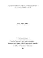
3.5 Top Sample is a spot sample obtained
6 in. (150 mm) below the top surface of the ture is blended in proportion to the volume of
liquid (Fig. i).
material in each compartment.
3.6 Upper Sample is a spot sample taken
at the mid-point of the upper third of the tank 3.16 Composite Spot Sample is a blend of
contents (Fig. i).
spot samples mixed in equal proportions for
3.7 Middle Sample is a spot sample ob-
tained from the middle of the tank contents testing. Tests may also be made on the spot
(Fig. i).
samples before blending and the results aver-
3.8 Lower Sample is a spot sample ob-
tained at the level of the fixed tank outlet or aged. Spot samples from crude oil tanks are
the swing line outlet (Fig. i).
collected as follows:
3.9 Clearance Sample is a spot sample
taken 4 in. (Io0 mm) below the level of the 3.16. I Three-Way-On tanks larger than
tank outlet (Fig. i).
1000-barrel ( I 60-m3) capacity which contain
3.10 Bottom Sample is one obtained from
the material on the bottom surface of the in excess of 15 ft (5 m) of oil, samples should
tank, container, or line at its lowest point.
be taken at the upper, middle, and lower, or
3.1 I Drain Sample is one obtained from
the draw-off or discharge valve. Occasionally, outlet, connection of the merchantable oil, in
a drain sample may be the same as a bottom
sample, as in the case of a tank car. the order named. On tanks of 1000-barrel
3.12 Water and Sediment Sample is one capacity and under, this method may be used
obtained with a thief to determine the amount
of nonmerchantable material at the bottom of also.
the tank.
3.16.2 Two-Way-On tanks larger than
3.13 Composite Sample is one made up of
1000-barrel capacity which contain in excess
equal portions of two or more spot samples
obtained from a tank. The term also applies of IO ft (3 m) and up to 15 ft (5 m) of oil.
to a series of line samples obtained from a
free-flowing pipe line. (See Fig. I for location samples should be taken at the upper and
of spot samples.)
lower, or outlet, connection of the merchant-
3.14 Single Tank Composite Sample is
able oil, in the order named. On tanks of
1000-barrel capacity and under, this method
may also be used.
3.17 Middle Spot Sample-On tanks
larger than 1000-barrel capacity containing IO
ft (3 m) or less of crude oil, one spot sample
should be taken as near the center of the ver-
tical column of oil as possible.
3.18 Continuous Sample is one obtained
from a pipeline in such manner as to give a
representative average of a moving stream.
3.19 Dipper Sample is one obtained by
placing a dipper or other collecting vessel imo
the path of a free-flowing stream so as to col-
lect a definite volume from the full cross sec-
tion of the stream at regular time intervals for
a constant rate of flow, or at time. intervals
varied in proportion t o the rate of flow.
3.20 Mixed Sample is one obtained after
mixing or vigorously stirring the contents of clean and free from holes and loose bits of
the original container, and then pouring out cork. Never use rubber stoppers. Contact of
or drawing off the quantity desired. the sample with the cork may be p r e w t e d by
wrapping tin or aluminum foil around the
3.21 Tube of Thief Sample is one obtained cork before forcing it into the bottle. Glass
with a sampling tube or specia; thief, either as stoppers must be a perfect fit. Screw caps
a core sample o r spot sample'from a specified must be protected by a fork disk faced with
point in the container. tin or aluminum foil, or other material that
will not affect petroleum or petroleum prod-
3.22 Borings Sample is one obtained by ucts.
collecting the chips made by boring holes with
a ship auger from top to bottom of the mate- 4.3 Cleoning Procedure-All sample con-
rial contained in a barrel, case, bag, or cake. tainers must be absolutely clean and free of
water, dirt, lint, washing compounds, naph-
3.23 Grab Sumpfe is one obtained by col- tha, or other solvents, soldering fluxes or
lecting loose solids in equal quantities from acids, corrosion, rust, and oil. Before using a
each part or package of a shipment and in container, rinse it with Stoddard solvent or
sufficient amount to be representative of all other naphtha of similar volatility. (it may be
sizes and components. necessary to use sludge solvents to remove all
traces of sediment and sludge from containers
3.24 Greose Sample is one obtained by previously used.) Then wash the container
scooping or dipping a quantity of soft or semi- with strong soap solution, rinse it thoroughly
liquid material, such as grease, from a with tap water, and finally with distilled
package in such a manner that the material water. Dry either by passing a current of
on the scoop or dipper is representative of the clean, warm air through the container or by
material in the package. placing it in a hot dust-free cabinet at 104 F
(40 C) or higher. When dry, stopper or cap
APPARATU s the container immediately. In the ordinary
field sampling of crude petroleum, washing
4. Sample Containers with soap and rinsing with water may be elim-
inated.
4. 1 Container Specifications-Sample con-
tainers may be clear or brown glass bottles, or 5. Sampling Apparatus
cans. The clear glass bottle is advantageous
because it may be examined visually for 5.1 Sampling apparatus is described in
cleanliness, and also allows visual inspection detail under each of the specific sampling
of the sample for free water or solid impuri- procedures. Clean. dry. and free all sampling
ties. The brown glass bottle affords some pro- apparatus from any substance that might con-
tection from light. The only cans permissible taminate the material. using the procedure
are those with the seams soldered on the exte- described in 4.3.
rior surfaces with a flux of rosin in a suitable
solvent. Such a flux is easily removed with SAMPLING INSTRUCTIONS AND
gasoline, whereas many others are very diffi-
cult to remove. Minute traces of flux may PRECAUTIONS
contaminate the sample so that results ob-
tained on tests for dielectric strength, resist- 6. Time anâ Place of Sampling
ance to oxidation, and sludge formation may
be erroneous. Sample containers for manual 6.1 Crude Petroleum: By mutual agree-
sampling of crude petroleum should be vapor- ment, samples may be taken either from
tight, equipped with delivery tube extending tanks or from pipelines. The pipeline samples
through the top to within Yz in. (12 mm) of the may be obtained by either manual or mechan-
bottom, and with a funnel and positive closure ical methods as described in Sections 18 to
to allow for submerged filling. 20, inclusive.
4.2 Contoiner Closure-Cork o r glass stop- 6.1.1 Storionory Tanks-Samples may be
pers, or screw caps of plastic or metal, may taken from tanks by mutual agreement as fol-
be used for glass bottles; screw caps only shall lows: composite spot, middle spot, all-levels,
be used for cans to provide a vaportight clo- running samples, or by sample cocks. Addi-
sure seal. Corks must be of good quality,
3
#lb D 270 - @ 2546
tional samples may be taken as deemed neces- ally permit a substantial relaxation of the electro-
static charge: under certain conditions a longer pe-
sary. riod may be deemed advisable.
6.1.2 Ship or Barge Tunk-Samples of 6.2.3 Packuge Lors (Cans, Drums, Barrels.-
or Boxes)-Take samples from a sufficient
crude petroleum shall be taken as follows: number of the individual packages to prepare
a composite sample which will be representa-
6.1.2.1 From the shore tanks before loading, tive of the entire lot or shipment. Select at
and both before and after discharging. These random the individual packages to be sam-
pled. The number of such random packages
shall be all-levels samples as described in 3.2 will depend upon several practical considera-
tions, such as:
or running samples as described in 3.3.
6.2.3.1 The tightness of the product specifi-
6.1.2.2 From the pipeline during loading cations,
and discharging. These shall be taken by the 6.2.3.2 The source and type of the material
and whether or not more than one production
procedures given in the Sections 18 to 20. batch may be represented in the lor. and
6.1.2.3 From the ship’s tanks after loading 6.2.3.3 Previous experience with similar
and before discharging. An all-levels sample shipments, particularly with respect to the
uniformity of quality from package to
as described in 3.2 or a running sample as de- package.
scribed in 3.3 shall be obtained from the ship’s
6.2.3.4 In most cases, the number specified
cargo tanks as follows: in Table 3 will be satisfactory.
Number of Grades Minimum Number of Samples 7. Obtaining Samples
I 3 compartments 7.1 Directions for sampling cannot be
made explicit enough to cover all cases. Ex-
Number of Compart- treme care and good judgment are necessary
ments Containing to ensure samples that represent the general
character and average condition of the mate-
One Grade rial. Clean hands are important. Clean gloves
may be worn but only when absolutely neces-
I to 2 each compartment sary, such as in cold weather, or when han-
3 to 6 dling materials at high temperature, or for
7 or more 2 compartments reasons of safety. Select wiping cloths so that
3 compartments lint is not introduced, contaminating samples.
6. I .3 Except as specifically exempted, when 7.2 As many petroleum vapors are toxic
and flammable. avoid breathing them or ig-
loading a ship, shore tank samples shall be niting them from an open flame or a spark
produced by static.
“official.” However. ship’s tank samples shall
7.3 When sampling relatively volatile prod-
also be tested for water and sediment, and for ucts (more than 2 Ib (0.14 kgf/cm2) Reid
vapor pressure (Rvp)), the sampling apparatus
other aspects of quality, when required; the shall be filled and allowed to drain before
drawing the sample. I f the sample is to be
results of these tests. together with tests of transferred to another container. this con-
tairirr shall also be rinsed with some of the
shore tank samples. shall be shown on the volatile product and then drained. When the
actual sample is emptied into this container,
cargo certificate. Except when specifically the samphng apparatus should be upended
into the opening of the sample container and
exempted, when discharging a ship, ship’s remain i n this position until the contents have
tank samples shall be ”official.” By mutual
agreement, line samples may be used for the
official samples, but samples from shore and
ship tanks are preferred.
6.2 Finished Products-When loading or
discharging finished products, take samples
from both shipping and receiving tanks, and
from the pipeline if required.
6.2.1 Ship o r Barge Tank-Sample each
product after the vessel is loaded or just be-
fore unloading.
6.2.2 Tank Curs-Sample the product after
the car is loaded or just before unloading.
NOTE 5-When taking samples from tanks sus-
pected of containing flammable atmospheres, pre-
cautions should be taken to guard against ignitions
due to static electricity. Metal or conductive ob-
jects. such as gage tapes. sample containers, and
thermometers. should not be lowered into or sus-
pended in. a compartment or tank which is being
filled.or immediately after cessation of pumping. A
waiting period of approximately I min will gener-
4
been transferred so that no unsaturated air during shipment. and to protect against mois-
will be entrainedin the transfer of the sample. lure and dust. cover the stoppers of glass bot-
tles with plastic caps that have been swelled in
7.4 When sampling nonvolatile liquid prod- water. wiped dry. placed over the tops of the
ucts (2 Ib (0.14 kgf/cm*) Rvp or less). the stoppered bottles, and allowed to shrink
sampling apparatus shall be filled and allowed tightly in place. The caps of metal containers
to drain before drawing the actual sample. If must be screwed down tightly and checked for
the actual sample is to be transferred to an- leakage. Postal and express office regulations
other container, the sample container shall be applying to the shipment of flammable liquids
rinsed with some of the product to be sampled must be observed.
and drained before it is filled with the actual
sample. 10. Labeling Sample Containers
8. Handling Samples 10.1 Label the container immediately after
a sample is obtained. Use waterproof and oil-
8.1 Volatile Samples-It is necessary to proof ink or a pencil hard enough to dent the
protect all volatile samples of petroleum and tag, since soft pencil and ordinary ink mark-
petroleum products from evaporation. ings are subject to obliteration from moisture.
Transfer the product from the sampling appa- oil smearing. and handling. include the fol-
ratus to the sample container immediately. lowing information:
Keep the container closed except when the
material is being transferred. When samples 10.1.1 Date and time (the period elapsed
of more than 16 Ib (1.12 kgf/cmz) Rvp are during continuous sampling and the hour and
being obtained, be sure to use containers minute of collection for dipper samples).
strong enough to meet local safety regula-
tions. After delivery to the laboratory, volatile IO. 1.Z Name of the sampler,
samples should be cooled before the container 10.1.3 Name or number and owner of the
is opened. vessel, car. or container.
10.1.4 Brand and grade of material, and
8.2 Lighr-Sensirive Samples-It is impor- 10.1.5 Reference symbol or identification
tant that samples sensitive to light, such as num ber.
gasoline containing tetraethyllead, be kept in
the dark, if the testing is to include the deter- SAMPLINPRGOCEDURES
mination of such properties as color, tetrae-
thyllead and inhibitor contents, sludge- l i . General Information
forming characteristics, stability tests, or neu-
tralization value. Brown glass bottles may be 1 1.1 The standard sampling procedures
used. Wrap or cover clear glass bottles imme- described in this method are summarized in
diately. I t is a definite advantage to use cov- Table I . Alternative sampling procedures may
ered cardboard cartons into which the sample be used if a mutually satisfactory agreement
bottles may be placed immediately after has been reached by the parties involved.
collection. Such agreement shall be put in writing and
signed by authorized officials.
8.3 Refined Materials-Protect highly re-
fined products from moisture and dust by BOTTLE OR BEAKERSAMPLING
placing paper, plastic, or metal foil over the
stopper and the top of the container. 12. Application
8.4 Conroiner Ouroge-Never completely 12.1 The bottle or beaker sampling proce-
fill a sample container, but allow adequate dure is applicable for sampling liquids of 16
room for expansion, taking into consideration Ib (1.12 kgf/cm2) Rvp or less in tank cars,
the temperature of the liquid at the time of tank trucks, shore tanks, ship tanks, and
filling and the probable maximum tempera- barge tanks. Solids or semiliquids that can be
ture to which the filled container may be sub- liquefied by heat may be sampled by this pro-
jected. cedure, provided they are true liquids at time
of sampling.
9. Shipping Samples
13. Apparatus
9.1 To prevent loss of liquid and vapors
13.1 A suitable sampling bottle or beaker,
5
#lb D 270 - 2546
as shown in Fig. 2. is required. Recommended T A PS A M P L I N G
uses and diameter of openings in the bottle or
beaker are given in Table 4. 15. Application
14. Procedure 15.1 The tap sampling procedure is appli-
cable for sampling liquids of 26 Ib (1.83
14. I All-Levels Sample-Lower the kgf/cm*) Rvp or less in tanks which are
equipped with suitable sampling taps or lines.
weighted, stoppered bottle or beaker as near This procedure is recommended for volatile
stocks in tanks of the breather and balloon-
as possible to the draw-off level, pull out the roof type. spheroids, etc. (Samples may be
taken from the drain cocks of gage glasses, if
stopper with a sharp jerk of the cord or chain the tank is not equipped with sampling taps.)
The assembly for tap sampling is shown in
and raise the bottle at a uniform rate so that Fig. 3.
it is about three-fourths full as it emerges NOTE 6-If R v p is more than i6 Ib (1.12
kgf/crn2)but not more than 26 Ib ( I 3 3 kgf/cm*) a
from the liquid. cooling bath as shown in 44.2. Fig. IO. shall be used
between the t a n k tap and the sample container 10
14.2 Running Sample-Lower the unstop- cool the sample and prevent volatilization of low-
boiling componenis.
pered bottle or beaker as near as possible to
16. Apparatus
the level of the bottom of the outlet connec-
16.1 Tank Tops-The tank should be
tion or swing line and then raise the bottle or equipped with at least three sampling taps
placed equidistant throughout the tank height
beaker to the top of the oil at a uniform rate and extending at least 3 ft ( I m) inside the
tank shell. A standard %-in. pipe with suit-
of speed such that it is about three-fourths full able valve is satisfactory.
when withdrawn from the oil. 16.2 Sample Cocks-Samples of crude pe-
troleum may be taken through sample cocks
14.3 Upper, Middle, and Lower Samples- properly placed in the shell of the tank. The
upper sample cock shall be located 18 in. (457
Lower the weighted. stoppered bottle to the mm) below the top of the tank shell; the lower
sample cock shall be located level with the
proper depths (Fig. I ) as follows: bottom of the outlet connection or at the top
of an upturned elbow or other similar fitting
Upper sample middle of upper third oí ihe iank con- if installed on the outlet connection; and the
tents middle sample cock shall be located halfway
Middle sample between the upper and lower sample cocks.
Lower sample middle of the iank conienis An additional cock for the clearance sample
level of the fixed iank ouilei or the should be located 4 in. (Io0 mm) below the
bottom of the outlet connection to determine
swingline ouilei whether the level of merchantable oil is at
least below this point. The sample cocks
Pull out the stopper with a sharp jerk of the should be located a minimum of 6 ft (1.8 m)
cord or chain and allow the bottle or beaker distant circurnferentially from the pipeline
to fill completely at the selected level, as evi- outlet and drain connections, and 8 ft (2.4 m)
denced by the cessation of air bubbles. When from the filling line connection. The sample
full, raise the bottle or beaker, pour off if cocks should be of Y4-in. ( I 9 mm) size, and the
small amount. and stopper immediately. lines should be of h - i n . nominal diameter for
crude oil of 18 deg API gravity or less. For
14.4 Multiple Tank Composiie Sample- lighter oil, %-in. (12.7-mm)-size cocks, with
Prepare a composite sample in the laboratory %-in. nominal diameter lines, should be used.
(not in the field) by mixing portions of the all-
levels samples as specified in 3.15.
14.5 Composiie Spor Sample-Prepare a
composite spot sample by mixing spot sam-
ples in equal proportions as specified in 3.16,
using either the three-way or the two-way
procedure, whichever applies.
14.6 Middle Spoi Sample-Obtain this
sample in the manner specified in Section
3.17.
14.7 Top Sample-Obtain this sample
(Fig. I ) in the same manner as specified in
10.3 but at 6 in. (150 mm) below the top sur-
face of the tank contents.
14.8 Handling-Stopper and label bottle
samples immediately after taking them, and
deliver to the laboratory in the original sam-
pling bottles.
6
$lb D 270 - .@ 2546
The lines should extend a minimum of 4 in. removed and the sample lines are filled with
(102 mm) inside -the tank shell, except on fresh oil from the tank.
floating-roof tanks, where flush installations
are necessary. All sample cocks should be 17.3.1 On tanks of 10,000-barrel (1600-m3)
equipped with sealable valves and plugged
inspection tees. capacity or smaller, samples of equal amounts
shall be taken from the lower. middle. and
16.2.1 On tanks of more than 10.000-barrel upper sample connections. A measuring cup
of proper size may be used to assure the
( 16ûû-m3)capacity. at least two sets of sample drawing of the proper quantity from each
cocks shall be installed, located equidistant sample cock.
apart. around the circumference of the tank.
Five or more sample cocks should be installed 17.3.2 On tanks of more than 10,000-barrel
per set, evenly spaced between lower and
upper sample levels. capacity. samples of equal amounts shall be
taken from each of the sample connections at
16.3 Tube-A delivery tube that will not each set of sample connections.
contaminate the product being sampled and
long enough to reach to the bottom of the 17.3.3 All samples shall be mixed in equal
sample container is required to allow sub- proportions for a composite sample, or the
merged filling. When a cooling bath is used samples may be tested separately and the re-
while tap sampling, a similar suitable tube suits averaged.
should be used between the tank tap and the
cooler inlet. 17.3.4 When crude oil in a tank fails to
reach the upper or middle sample cocks on u
16.4 Sample Containers-Use clean, dry tank equipped with three sample cocks. it is
glass bottles of convenient size and strength to suggested that the sample for the run be oh-
receive the samples. If the vapor pressure of tained as follows: if the level of the oil is
the product to be sampled is between 16 and nearer the upper sample cock than the mid-
26 Ib (1.12 and 1.83 kgf/cm2) Rvp, protect dle, two thirds of the sample shall be taken
the bottle with a metal cover until the sample from the middle sample cock and one-third
is discarded. I n some cases, such as the sam- from the lower. If the level of oil is nearer the
pling of crude petroleum, metal containers middle sample cock than the upper, one half
may be used instead of glass bottles. of the sample shall be taken from the middle
and one half from the lower. If the level of
17. Procedure the oil is below the middle sample cock. all of
the sample shall be taken from the lower
17.1 Before a sample is drawn, nush the cock.
tap (or gage glass drain cock) and line until
they are purged completely. Connect the clean C O N T I N U O USSA M P L I N G
delivery tube to the tap. Draw upper, middle,
or lower samples directly from the respective 18. Application
taps after the flushing operation. Stopper and
label the sample container immediately after 18.1 The continuous sampling procedure is
filling, and deliver it to the laboratory. applicable for sampling liquids of 16 (1.12
.kgf/cm2) Rvp or less and semiliquids in pipe-
17.2 When a sample cooler is used during lines, filling lines, and transfer lines. The con-
the tap sampling operation, flush the tap (or tinuous sampling may be done manually or by
gage glass drain cock). Then, using a section using automatic devices.
of clean tubing, connect the tap to the cooler
inlet. Flush the cooler throughly, after which 19. Apparus
connect the clean delivery tube to the cooler
outlet and proceed with the sampling opera- 19.1 Sampling Probe-The function of the
tion. sampling probe is to withdraw from the flow
stream a portion that will be representative of
17.3 In the sampling of crude petroleum, the entire stream. The apparatus assembly for
check for merchantable oil at the clearance continuous sampling is shown in Fig. 4.Probe
sample cock. Flush each sample connection designs that are commonly used are as fol-
until all oil from the previous run has been lows:
19.1.1 A tube extending to the center of the
line and beveled at a 45-deg angle facing up-
7
stream (Fig. 4(a)). for analvsis. and its composition should be
19.1.2A long-radius forged elbow or pipe identical with the composition of the batch
flowing in the line while the sample is being
bend extending to the center line of.the pipe taken. An autom. sampler installation nec-
and facing upstream. The end of the probe essarily includes n v t only the automatic sam-
should be reamed to give a sharp entrance pling device that extracts the samples from
edge. (Fig. 4(b)). the line. but also a suitable probe, connecting
lines, auxiliary equipment, and a container in
19.1.3 A closed-end tube with a round ori- which the sample is collected. Automatic
fice spaced near the closed end which should samplers may be classified as follows:
be positioned i n such a way that the orifice is
in the center of the pipeline and is facing the 19.4.i Continuous Sampler, Time C.de
stream as shown in Fig. 4(r). (Nonproporrional) Types-A sampler de-
signed and operated in such a manner that it
19.2 Since the fluid pumped ma\ ,ot in all transfers equal increments of liquid from the
cases be homogeneous, the positit,.. m d size pipeline to the sample container at a uniform
of tht -Jmpling probe should be >uch as to rate of one or more increments per minute is
minimize stratification or dropping out of a continuous sampler.
heavier particles within the tube or the dis-
placement of oil within the tube as a result of 19.4.2 Conrinuous Sampler, Flow-Respon-
variation in gravity of the flowing stream. The sive (Proportional) Tvpe-A sampler that is
sampling probe should be located preferably designed and operated in such a manner that
in a vertical run of pipe and as near as prac- it will automatically adjust the quantit? of
ticable to the point where the oil passes to the sample in proportion to the rate of flow is a
receiver. The probe should always be in a hor- flow-responsive (proportional) sampler. Ad-
izontal position. justment of the quantity of sample may be
made either by varying the frequency of trans-
19.2.1 The sampling lines should be as ferring equal increments of sample to the
short as practicable and should be cleared sample container, or by varying the volume of
before any samples are taken. the increments while maintaining a constant
frequency of transferring the increments to
19.2.2A suitable device for mixing the the sample container. The apparatus assembly
fluid flow to ensure a homogeneous mixture for continuous sampling is shown in Fig. 4.
at all rates of íìow and to eliminate stratifica-
tion should be installed upstream of the sam- 19.4.3 Inrermìrienr Sampler-A sampler
pling tap. Some effective devices for obtaining that is designed and operated in such a
a homogeneous mixture are as follows: reduc- manner that it transfers equal increments of
tion in pipe size; a series of baffles; orifice or liquid from a pipeline to the sample container
perforated plate; and a combination of any of at a uniform rate of less than one increment
these methods. per minute is an intermittent sampler.
19.2.3 The design or sizing of these devices 19.5 Standards of Insrallarion-A ut omat ic
is optional with the user, as long as the flow sampler installations should meet all safety
past the sampling point is homogeneous and requirements in the plant or area where used.
stratification is eliminated. and should comply with American National
Standard Code for Pressure Piping, and other
19.3 TO control the rate at which the applicable codes ( A N S I 831.1).The sampler
sample is withdrawn, the probe or probes should be so installed as to provide ample
should be fitted with valves or plug cocks. access space for inspection and maintenance.
19.4 Auromaric Sampling Devices-If 19.5.I Small lines connecting various ele-
mutually agreeable, automatic line-sampling ments of the installation should be so ar-
devices that meet the standards set out in 19.5 ranged that complete purging of the auto-
may be used to withdraw line samples for the matic sampler and of all lines can be acconi-
plished effectively. All fluid remaining in the
purpose of determining gravity, water, and sampler and the lines from the preceding
sediment, and other characteristics required in sampling cycle should be purged immediately
the custody transfer of crude petroleum.
These devices may also be used in obtaining
samples of petroleum products. The quantity
of sample collected must be of sufficient size
8
before the start of any given sampling opera- of pumping.
tion. 19.6.2 I f the samplini o f the delivery tank
19.5.2 In those cases where the sampler is to be delayed beyond 1 h. then the tank se-
design is such that complete purging of the lected must be equipped with an adequate
sampling lines and the sampler is not possible, mixing means. For valid comparison, the
a small pump should be installed in order to sampling of the delivery tank must be com-
circulate a continuous stream from the sam- pleted within 8 h after cessation of pumping.
pling tube past or through the sampler and even though the tank is equipped with a
back into the line. The automatic sampler motor-driven mixer.
should then withdraw the sample from the
sidestream through the shortest possible 19.6.3 When making a normal full-tank
connection. delivery from a tank, a properly secured
sample may be used to check the results of
19.5.3 Under certain conditions, there may the sampler if the parties mutually agree to
be a tendency for water and heavy particles to this procedure.
drop out in the discharge line from the sam-
pling device and appear in the sample con- 19.7 Receiver-The receiver must be a
tainer during some subsequent sampling pe- clean, dry container of convenient size to re-
riod. T o circumvent this possibility, the dis- ceive the sample. All connections from the
charge pipe from the sampling device should sample probe to the sample container must be
be free of pockets or enlarged pipe areas, and free of leaks. Two types of container may be
preferably should be pitched downward to the used, depending upon service requirements:
sample container.
19.7.I Atmospheric Container-The at-
19.5.4 To ensure clean, free-flowing lines, mospheric container shall be constructed in
piping should be designed for periodic such a way that it retards evaporation loss
cleaning. When sampling waxy or high-vis- and protects the sample from extraneous ma-
cosity oils, it may be necessary to heat the terial such as rain, snow, dust, and trash. The
lines and sampler. construction should allow cleaning, interior
inspection. and complete mixing of the sample
19.6 Field Calibration-Composite sam- prior to removal. The container should be
ples obtained from the automatic sampler in- provided with a suitable vent.
stallation should be verified for quantity per-
formance in a manner that meets with the 19.7.1 Closed Container-The closed con-
approval of all parties concerned. at least tainer shall be constructed in such a manner
once a month and more often if conditions that it prevents evaporation loss. The con-
warrant. In the case of time-cycle samplers, struction must allow cleaning, interior inspec-
deviations in quantity of the sample taken tion and complete mixing of the sample prior
should not exceed *5 percent for any given to removal. The container should be equipped
setting. In the case of flow-responsive sam- with a pressure-relief valve.
plers, the deviation in quantity of sample
taken per 1000 barrels of flowing stream 20. Procedure
should not exceed 15 percent. For the pur-
pose of field-calibrating an installation, the 20. I Nonautomatic Sample:
composite sample obtained from the auto- 20.1.1 Adjust the valve or plug cock from
matic sampler under test should be verified the sampling probe so that a steady stream is
for quality by comparing on the basis of phys- drawn from the probe. Whenever possible, the
ical and chemical properties, with either a rate of sample withdrawal should be such that
properly secured continuous nonautomatic the velocity of liquid flowing through the
sample or tank sample. The tank sample probe is approximately equal to the average
should be taken under the following condi- linear velocity of the stream flowing through
tions: the pipeline. Measure and record the rate of
sample withdrawal as gallons per hour. Divert
19.6.1 The batch pumped during the test the sample stream to the sampling container
interval should be diverted into a clean tank continuously or intermittently to provide a
and a sample taken within I h after cessation quantity of sample that will be of sufficient
size for analysis.
9
20.1.2 in sampling crude petroleum, sam- crude petroleum. the analysis of the sample
ples of 1/2 pt (0.24 liter) or more should be may be performed in the field.
taken every hour or less-whichever is
thought necessary. By mutual agreement, the NOTE i-When sampling semiliquida. heai ihe
sample period may be increased to 2-h inter-
vais. it is important that the size of the sam- sampler lines. sampler. and receiver io a tempera-
ples and the intervals between the sampling ture just sufficient to keep the material liquid and
operations be uniform for each batch of mate- to assure accurate operaiion o f lhe sampling de-
rial to be sampled. vices.
20.1.2.1 The sample of crude petroleum D I P P E RS A M P L I N G
should be placed in a closed container and at
the end of a 24-h period. or at a predeter- 21. Application
mined period, the combined samples should
be gently, yet thoroughly, mixed and a com- 21.1 The dipper sampling procedure is ap-
posite sample taken for test purposes. The plicable for sampling liquids of 2 Ib (0.14
sample container should be vapor-tight, kgf/cmz) Rvp or less and semiliquids where a
equipped with a delivery tuhe extending free or open discharge stream exists, as in
through the top to within '12 in. (i2 mm) of small filling and transfer pipelines (2-in. di-
the bottom, and with a funnel and positive ameter or less) and filling apparatus for bar-
closure for allowing submerged filling. The rels, packages. and cans.
sample container should be stored in a cool,
dry place; exposure to direct sunlight should 22. Apparatus
be avoided.
22.1 Dipper-Use a dipper with a flared
20.1.2.2 Duplicate line samples obtained bowl and a handle of convenient length. made
for gravity, and water and sediment tests may of material such as tinned steel that will not
be taken, according to the instructions for affect the product being tested. The dipper
sampling, and the tests made at that time. A should have a capacity suitable for the
record of the results of such tests should be amount to be collected (Section 23) and must
kept and averaged for a 24-h period, or for a be protected from dust and dirt when not
predetermined period. The composite or av- being used.
erage of hourly samples is acceptable.
22.2 Sample Conrainer-Use a clean, dry
20.1.3 Label the sample and deliver it to container of the desired size.
the laboratory in the container in which it was
collected. 23. Procedure
20.2 Auromaiic Sampling-Purge the 23.1 insert the dipper in the free-flowing
sampler and the sampling lines immediately stream so that a portion is collected from the
before the start of a sampling operation. i f full cross section of the stream. Take portions
the sampie design is such that complete at time intervals chosen so that a complete
purging is not possible, circulate a continuous sample proportional to the pumped quantity
stream from the probe past or through the is collected. The gross amount of sample col-
sampler and back into the line. Withdraw the lected should be approximately O. I percent.
sample from the side stream through the au- but not more than 40 gal (IO5 liters). of the
tomatic sampler using the shortest possible total quantity being sampled. Transfer the
connections. Adjust the sampler to deliver not portions into the sample container as soon as
less than one and not more than 40 gal (151 collected. Keep the container closed. except
liters) of sample during the desired sampling when pouring a dipper portion into it. As
period. For time-cycle samplers, record the soon as all portions of the sample have been
rate at which sample increments were taken collected, close and label the sample con-
per minute. For flow-responsive samplers, tainer, and deliver it to the laboratory.
record the proportion of sample to total
stream. Label the samples and deliver them to T U B ES A M P L I N G
the laboratory in the containers i n which they
were collected. Altcrnatively, in the case of 24. Application
24.1 The tube sampling procedure is appli-
cable for sampling liquids of 2 Ib (0.14
kgf/cm*) Rvp or less and semiliquids in
drums, barrels, and cans.
10
25. Apparatus manner as from drums and barrels (26.1).
using a tube of proportionately smaller di-
25.1 Tube-Either a glass or metal tube mensions. For cans of less than 5-gal capac-
may be used, designed so that it will reach to ity. use the entire contents as the sample. se-
within about '/a in. (3.2 mm) of the bottom lecting cans at random as indicated in Table 3
and have a capacity of approximately 1 pt or in accordance with agreement between the
(0.5 liters) or I qt ( I liter). A metal tube suit- purchaser and the seller.
able for sampling 50-gal (190-liter) drums is
shown in Fig. 5. T w o rings soldered to oppo- T H I E FS A M P L I N G
site sides of the tube at the upper end are
convenient for holding it by slipping two fin- 27. Application
gers through the rings. thus leaving the thumb
free to close the opening. 17.1 The thief sampling procedure is appli-
cable for obtaining bottom samples (Fig. I).
25.2 Sample Conrainen-Use clean. dry or of semiliquids in tank cars and storage
cans or glass bottles. tanks.
26. Procedure 27.2 The thief is also widely used in sam-
pling crude petroleum in storage tanks. In this
26.1 Drums anú Barrels-Place the drum application it may be used for taking samples
or barrel on its side with the bung up. I f the at different levels as well as for bottom sam-
drum does not have a side bung. stand it up- ples of nonmerchantable oil and water at the
right and sample from the top. I f detection of bottom of the tank.
water, rust or other insoluble contaminants is
desired, let the barrel or drum remain in this 28. Apparatus
position long enough to permit the contami-
nants to settle. Remove the bung and place it 28.1 Thiej-The thief shall be designed so
beside the bung hole with the oily side up. that a sample can be obtained within !h in.
Close the upper end of the clean. dry sam- (13 mm', of the bottom of the car or tank.
pling tube with the thumb, and lower the tube Two types of thiefs are illustrated in Fig. 6 .
into the oil for a depth of about 1 ft (0.3 m). One type is lowered into the tank with valves
Remove the thumb, allowing oil to flow into open to permit the oil to flush through the
the tube. Again close the upper end with the container. When the thief strikes the bottom
thumb and withdraw the tube. Rinse the tube of the kink. the valves shut automatically to
with the oil by holding it nearly horizontal trap a bottom sample. The other type has a
and turning it so that the oil comes in contact projecting stem on the valve rod which opens
with that part of the inside surface that will the valves automatically as the stem strikes
be immersed when the sample is taken. Avoid the bottom of the tank. The sample enters the
handling any part of the tube that will be container through the bottom valve and air is
immersed in the oil during the sampling oper- released simultaneously through the top. The
ation. Discard the rinse oil and allow the tube valves snap shut when the thief is withdrawn.
to drain. Insert the tube into the oil again, A core-type thief similar to that shown in Fig.
holding the thumb against the upper end. (If 6 (b). with a uniform cross section and
an all-levels sample is desired, insert the tube bottom closure and with a capacity depending
with the upper end open.) When the tube upon the size of the sample required, may be
reaches the bottom, remove the thumb and used for sampling crude petroleum. The thief
allow the tube to fill. Replace the thumb. should be capable of penetrating the oil in the
withdraw the tube quickly and transfer the tank to the required levei, mechanically
contents to the sample container. Do not equipped to permit filling at any desired level,
allow the hands to come in contact with any and capable of being withdrawn without
part of the sample. Close the sample con- undue contamination of the contents. The
tainer; replace and tighten the bung in the thief may be equipped with the following:
drum or barrel. Label the sample container
and deliver it to the laboratory. 28.1.1 Sample cocks for obtaining samples
for the determination of water and sediment,
26.2 Cans-Obtain samples from cans of
5-gai (19-liter) capacity o r larger in the same 28.1.2 Extension rods for use in obtaining
samples at levels corresponding with require-
11
ments for high connections or for samples to eign substances from the surface of the mate-
determine high settled water and sediment rial. Bore three test holes through the bod! of
levels, the material, one at the center. the other IWO
halfway between the center and the edge Gf
28.1.3 Water and sediment gage for deter- the package on the right and left sides. respec-
mining the height of water and sediment in tively. I f any foreign matter is removed from
the thief, the interior of the material during the boring
operation, include it as pari of the borings.
28.1.4 Windshield to be used when taking Put the three sets of borings in individual
the gravity and temperature of the oil, sample containers. label and deliver theni to
the laboratory.
28.1.5 Opener to break the tension on the
valve or slide at any desired level, 33. Laboratory Inspection
28.1.6 A thief cord marked so that sample 33.1 I f there are any visible differences in
can be taken at any depth in the vertical cross the samples, examine and test each set of bor-
section of the tank. and ings at the laboratory. Otherwise, combine
the three sets of borings into one sample. I f
28.1.7 Hook to hang the thief in the hatch subdivision of the borings is desired, chill,
vertically. pulverize (if necessary). mix. and quarter the
borings until reduced to the desired amount.
28.2 Sample Confainers-Use clean, dry
cans or glass bottles. G R A BSAMPLING
29. Procedure 34. Application
29.1 Lower the clean, dry thief through the 34.1 The grab sampling procedure is appli-
dome of the tank car or tank hatch until it cable for sampling all lumpy solids in bins,
strikes the bottom. When full, remove the bunkers, freight cars, barrels, bags, boxes,
thief and transfer the contents to the sample and conveyors. It is particularly applicable for
container. Close and label the container im- the collection of green petroleum coke sam-
mediately, and deliver it to the laboratory. ples from railroad cars and for the prepara-
tion of such samples for laboratory analysis.
29.2 I n the sampling of crude petroleum, Refer to ASTM Method D 346, Sampling
lower the clean, dry thief slowly into the oil to Coke for Analysis,' when other methods of
the desired depth, trip the thief t o secure the shipping or handling are used.
sample and raise slowly to avoid agitation.
The proper depths for sampling are described 34.2 Place o/ Sampling-Petroleum coke
in Section 3. may be sampled while being loaded into rail-
road cars from piles or after being loaded into
BORING SAMPLING railroad cars from coking drums.
30. Application 35. Apparatus
30.1 The boring sampling procedure is ap- 35. I S a m p l e Container-A polyethylene
plicable for sampling waxes and soft solids in pail of approximately IO-qt (IO-liter) capacity.
barreis, cases, bags, and cakes when they
cannot be melted and sampled as liquids. 35.2 Scoop, stainless steel or aluminum,
No. 2 size.
31. Apparatus
36. Procedure
31.1 Ship Auger-Use a ship auger V4 in.
(19 mm) in diameter, similar to that shown in 36.1 Sampling-Lumpy solids are usually
Fig. 7,and of sufficient length to pass through heterogeneous and therefore are difficult to
the material to be sampled. sample accurately. It is preferable ta take
samples during the unloading of cars, or
3I .2 Sample Containers-Use clean, wide- during transit of the material by conveyors.
mouth, metal containers or glass jars with From material in transit, obtain a number of
covers. portions at frequent and regular intervals and
combine them.
32. Procedure
32.1 Remove the heads or covers of barreis
and cases. Open bags and wrappings of cakes.
Remove any dirt, sticks, string, or other for-
12
36.2 When sampling from railroad cars. taining samples representative of production
use one of the following procedures: lots or shipments of lubricating greases. or of
soft waxes or soft bitumens similar to grease
36.2.1 Being Loaded from a Pile-Take a in consistency. The procedure is necessarily
full scoop of sample at each of the five sam- quite general to cover the wide variety of con-
pling points shown in Fig. 8 and deposit in the ditions encountered. and may require niodifi-
polyethylene pail. Cover the sample and de- cation to meet individual specifications. Pro-
liver to the laboratory. Each sampling point ceed in accordance with Sections 4 to IO. par-
shall be located equidistant from the sides of ticularly those pertaining to precautions. care.
the railroad car. and cleanliness. except where they conflict
with Sections 38 to 40.
36.2.2 Railroad Cars After Direct Loading
from Coking Drums-At any five of the sam- 38. Inspection
pling points shown in Fig. 9. take a full scoop
of coke from about I ft (0.3 mì below the sur- 38.1 I f the material is ;i lubricating grease
face and deposit it in the polyethylene pail. and inspection is made at the manufacturing
Cover the sample and deliver to the labora- plant. take samples from the finished shipping
tory. containers of each production batch or lot.
Never take grease samples directly from
36.3 When sampling from conveyors. take grease kettles, cooling pans. tanks. or proc-
one scoop for each 8 to I O tons (725 to 900 essing equipment. Do not sample the grease
kg) of coke transported. These samples may until it has cooled to a temperature not more
be handled separately. or composited after all than 15 F (8 C ) above that of the air surround-
samples representing the lot have been taken. ing the containers and until it has been in the
finished containers for at least I2 h. When the
36.4 When sampling from bags. barrels. or containers for a production batch of grease
boxes, obtain portions from a number of are of different sizes. treat the grease in each
packages selected at random as shown in size of container as a separate lot. When
Table 3. or in accordance with the agreement inspection is made at the place oí' delivery.
between the purchaser and the seller. obtain ;1 sample from each shipment. I f a
shipment consists of containers from more
36.5 Quartering-Carefully mix the sample than one production batch (lot numbers),
and reduce it in size to a convenient labora- sample each such batch separately.
tory sample by the quartering procedure de-
scribed in Method D 346. Perform the quart- 38.2 I f the material being inspected is of
ering operation on a hard. clean surface. free grease-like consistency. but is not actually a
from cracks, and protected from rain. snow, lubricating grease. but some mixture of heav)
wind. and sun. Avoid contamination with cin- hydrocarbons such as microcrystalline waxes
ders, sand, chips from the floor, or any other or soft bitumens. it will be permissible to take
material. Protect the sample from loss o r gain samples from pans. tanks, or other processing
of moisture or dust. Mix and spread the equipment, as well as from containers of the
sample in a circular layer, and divide it into finished product. The grease sampling niethod
quadrants. Combine two opposite quadrants shall be applicable to such s:ocks only if for
to form a representative reduced sample. I f some reason it is not possible to apply heat
this sample is still too large for laboratory and convert the material into a true liquid.
purposes, repeat the quartering operation. In
this manner. the sample will finally be re- 39. Sample Size
duced to a representative. suitable size for
laboratory purposes. Label and deliver the 39.1 Select containers at random from
sample to the laboratory in a suitable con- each lot or shipment to give the desired quan-
tainer. Subdivision may be made in the labo- tity specified in Table 5.
ratory by using a riffle sampler as described
in ASTM Method D 271, Laboratory Sam- 40. Procedure
pling and Analysis of Coal and Coke.'
40. I Inspection-Examine the opened con-
G R E A S ES A M P L I N G tainers to determine whether the grease is
homogeneous. comparing the grease nearest
37. Application
37.1 This method covers practices for ab-
13
- 4 2546
the outer surfaces of the container with that SAMPLINI NGD U S T R I A L A R O M A T I C
in the center, at least 6 in. (150 mm) below H YDROCAR BOSS
the top surface, for texture and consistency.
When more than one container .of a lot or 41. Application
shipment is opened, also compare the grease
in the respective containers. 41.1 For obtaining samples of industrial
aromatic hydrocarbons (benzene. toluene.
40.2 Sampling-If no marked difference in xylene. and solvent naphthas), proceed in ac-
the grease is found, take one portion from the cordance with Sections 4 to 6. particularly
approximate center and at least 3 in. (76 mm) those pertaining to precautions, care. and
below the surface of each opened container, in cleanliness.
sufficient quantity to provide a composite
sample of the desired quantity (Table 5). SAMPLIFNOGR SPECIFITCESTS
Withdraw portions with a clean scoop, large
spoon, or spatula and place them in a clean 42. Special Precautions
container. Very soft, semifluid greases may be
sampled by dipping with a I-lb (0,s-kg) can or 42.1 Special sampling precautions and in-
suitable dipper. I f any marked difference in structions are required for some ASTM
the grease from the various locations of an methods of test and specifications. Such in-
opened container is found, take two separate structions, Sections 43 to 48, supplement the
samples of about 1 Ib each. one from the top general procedures of this method and su-
surface adjacent to the wall, and the other persede them if there is a conflict. ASTM
from the center of the container. at least 6 in. methods in this category are as follows:
(150 mm) below the top surface. I f any
marked variations are noted between different Sections
containers of ;i lot or shipment. take separate AST \ S Methods of Test for:
samples of about I Ib (0.5 kg) from each con-
tainer. When more than one sample of a D 216-Distillarion of Natural Gabo-
batch or shipment is taken because of lack of line' ~ . . . . ~ ~ . . . . . ~ ~ ~43. ~ ~ ~ . . . . ~ . ~
uniformity, send them to the laboratory as
separate samples. D 323-Vapor Pressure of Petroleum
Products (Reid Method)? , . . . . . . . 14
40.3 Handling Samples-if more than one
portion is required to represent a lot or ship- D 525-Oxidation Stability o f Gaso-
ment of grease softer than 175 penetration
(see ASTM Method D 217, Test for Cone line (Induction Period Method)'. . . 45
Penetration of Lubricating Grease).' prepare D 873-Oxidation Stability of Avia-
a composite sample by mixing equal portions
thoroughly. Use a large spoon or spatula in a tion Fuels (Potential Residue
clean container. Avoid vigorous mixing or
working of air into the grease. As grease Method)'. . . . . . . . , . . . , . . . ., .. . . 45
samples become partially "worked" in being
removed from containers. the procedure is not D26X-Volatile Solvents for Usc in
suitable for obtaining samples of greases Paint. Varnish. Lacquer. und Rc-
softer than 175 penetration on which un-
worked penetration is to be determined. For lated Products5 . . . . . . . . . . . . . . . . . 46
greases having a penetration less than i 75, cut
samples from the container with a knife in the D 1856-Rccovery of Asphalt from
form of blocks about 6 by 6 by 2 in. (150 by
150 by SO mm). I f required, make unworked Solution by Abson Method.6 or. D
penetration tests on blocks as procured, and
other inspection tests on grease cut from the 2 172-Ouantitaiive Extraction of
blocks. Bitumen' from Bituminous Paving
Mixtures6_ . . _ . . . . ._.. . . . .. . _ . . 47
D 244-Emulsified Asphalts6 . . . . . . . 48
43. Distillation of Natural Gasoline
43.1 When obtaining samples of natural
gasoline which ;ire to be tested using Method
D 216, the bottle sampling procedure. Section
14 is preferred. Before obtaining the sample,
precool the bottle by immersing it in the
product. allow it to till. and discard the first
filling. I f the bottle procedure cannot be used.
obtain the sample by the tap procedure, and
with the use of the cooling bath. as described
in Section 17. Do not agitate the bottle while
' Annual Book o l A S T M Siondards. Parc 29.
'Annual Book oJ'ASTM Srandards. Puri 15.
14
#]b D 270 - 2546
drawing the sample. After obtaining the sam- to the gasoline chamber of the vapor pressure
ple, close the bottle immediately with a tight- apparatus. Open-type containers have a single
fitting stopper and store it in an ice bath or opening which permits samplins by immer-
refrigerator at a temperature of 32 to 40 F (O sion. Closed-type containers have two open-
to 4.5 0 . ings. one in each end ( o r the equivalent
thereof), fitted with valves suitable for sam-
44. Reid Vapor Pressure pling by water displacement or by purging.
44.1 When sampling products that are to 44.1.4 Transfer Connecrions-The transfer
be tested using Method D 323. observe the connection for the open-type container con-
following precautions and instructions: sists of an air tube and a liquid delivery tube
assembled in a cap or stopper. The air tube
44.I . I Precaurions--Vapor pressures are ex- extends to the bottom of the container. One
tremely sensitive to evaporation losses and to end of the liquid delivery tube is flush with
slight changes in composition. When obtaining. the inside face of the cap or stopper and the
storing. or handling samples. obsene the nec- tube is long enough to reach the bottom of
essary precautions to ensure samples represent-
ative of the product and satisfactory for Reid the gasoline chamber while the sample i s
vapor pressure tests Official samples should be
taken by. or under the immediate supervision being transferred to the chamber. The transfer
of a person of judgment. skill. and sampling connection for the closed-type container con-
experience. If sampling or sample requirements sists of a single tube with a connection suit-
for other tests differ from those described in able for attaching it to one of the openings of
44. I .2 to 44. I .9. obtain a separate sample for the sample container. The tube is long enough
the Reid vapor pressure test. Never prepare to reach the bottoni of the gasoline chamber
composite samples for this test. Make certain while the sample is being transferred.
that containers which are to be shipped by
common carrier conform to I.C.C.. state. or 44.I .5 Sampling Open Tanks-Use clean
local regulations. When flushing or purging containers of the open type when sampling
lines or containers. observe rhe perrinent r e p - open tanks and tank cars. An all-level sample
larions and precaurions againsr fire. explosion. obtained by the bottle procedure, Section 12.
and orher haiards. is recommended. Before taking the sample.
flush the container b’ imniersiny it in the
44.1.2 Cooling Bath-A bath (Fig. IO) of product to be sanipled. Then obtain the
sufficient size to hold the sample container sample imniediately. Pour off enough so that
and a cooling coil of about 25 ft (8 m) of the container will be 70 to 80 percent full and
copper tubing ( % in. (9 mm) or less outside close it promptly. Label the container and de-
diameter) shall be required when using the liver it to the laboratory.
procedure described in 44.1.7. One end of the
coil is provided with a connection for at- 44.1.6 Sampling Closed Tanks-Con-
taching it to the tank sampling tap or valve. tainers of either the open or closed type ma!
The other end is fitted with a suitable valve be used to obtain samples from closed or
(outlet) of good quality. A removable copper pressure tanks. I f the open type is used.
tube of in. or less outside diameter and of follow the cooling bath procedure described in
sufficient length to reach the bottom of the 44.1.7. I f the closed type is used. obtain the
sample container shall be connected to the sample using the water displacement proce-
open end of the outlet valve. dure. (44.1.8). or the pursing procedure.
(44.I .9). The water displacement procedure is
44. I .3 Sample Containers-Use containers preferable because the flow of product in-
of not less than I qt ( I liter) nor more than 2- volved in the purging procedure may be haz-
gal (7.5-liter) capacity, of sufficient strength ardous.
to withstand the pressures to which they may
be subjected, and of a type that will permit 44.1.7 Cooling Bath Procedure-When
replacement of the cap or stopper with suit- using a container of the open type. keep it at
able connections for transferring the sample a temperature of 3 1 to 40 F ( O to 4.5 C i
during the sampling operation b! using the
cooling bath (Fig. IO). Connect the coil to the
tank sampling tap or valve Lind flush i t with :I
#lb D 270 - 9 2546
sufficient amount of product to ensure com- open both the upper and lower valves slightly
plete purging. When obtaining a sample. to remove the excess. Promptly seal and lahel
throttle the outlet valve so that the pressure in the container and deliver it to the laboratory.
the coil will be approximately the same as
that in the tank. Fill the container once to 45. Oxidation Stability
wash and cool it, and discard the wash
product. Then draw the sample immediately. 45.1 When sampling products that are to
Pour off enough so that the container will be be tested for oxidation stability in accordance
70 to 80 percent full and close it promptly. with Method D 525. using ASTM Method D
Label the container and deliver it to the labo- 873, or by equivalent methods. observe the
ratory. following precautions and instructions:
44.1.8 Warer Displacemenr Procedure- 45. I . I Precaurions-Very small amounts
Completely fill the closed-type container with (as low as 0.001 percent) of some materials,
water and close the valves. The water should such as inhibitors, have a considerable effect
be at the same temperature or lower than that upon oxidation stability tests. Avoid contami-
of the product to be sampled. While permit- nation and exposure to light while taking and
ting a small amount of product to flow handling samples. To prevent undue agitation
through the fittings. connect the top or inlet with air which promotes oxidation. do not
valve of the cmtainer to the tank sampling pour. shake, or stir samples to any greater
tap or valve. Then open ail valves on the inlet extent than necessary. Never expose them to
side of the container. Open the bottom or temperatures above those necessitated by
outlet valve slightly to allow the water to he atmospheric conditions.
displaced slowly by the sample entering
container. Regulate the flow so that there is 45.1.2 Sample Containers-Use only
no appreciable change in pressure within the brown glass or wrapped clear glass bottles as
container. Close the outlet valve as soon as containers, since it is difficult to make certain
gasoline discharges from the outlet; then in that cans are free of contaminants, such as
succession close the inlet valve and the sam- rust and soldering flux. Clean the bottles by
pling valve on the tank. Disconnect the con- the procedure described in 43 and, if possible.
tainer and withdraw enough of the contents so finish with a cleaning solution of sulfuric acid
that it will be 70 to 80 percent full. I f the and potassium dichromate. Rinse thoroughly
vapor pressure of the product is not high with distilled water. dry. and protect the bot-
enough to force liquid from the container, tles from dust and dirt.
open both the upper and lower valves slightly
to remove the excess. Promptly seal and label 45. I .3 Samplinx-An all-levels sample
the container. and deliver it to the laboratory. obtained by the bottle proc: lure. 14. I . is rec-
ommended because the su,*rpleis taken di-
44. I .9 PurRing Procedure-Connect the rectly in the bottle. This reduces the possi-
inlet valve of the closed-type container to the bility of air absorption, loss of vapors, and
tank sampling tap or valve. Throttle the contamination. Just before sampling. rinse the
outlet valve of the container so that the pres- bottle with the gasoline to be sampled.
sure in it will be approximately equal to that
in the container being sampled. Allow a 46. Lacquer Solvents and Diluents
volume of product equal to at least twice that
of the container to flow through the sampling 46.1 When sampling b u l k shipments of
system. Then close all valves, the outlet valve lacquer solvents and diluents which are to be
first, the inlet valve of the container second. tested using Method D 268, observe the fol-
and the tank sampling valve last, and discon- lowing precautions and instructions:
nect the container immediately. Withdraw
enough of the contents so that the sample 46.1.1 Tanks and Tank Cars-Obtain
container will be 70 to 80 percent full. I f the upper and lower samples (Fig. I ) of not more
vapor pressure of the product is not high than 1 qt ( I liter) each by the bottle proce-
dure. 14.2. Prepare in the laboratory a com-
enough to force liquid from the container, posite sample of not less than % gai (2 iitecs)
by mixing equal parts of the upper and lower
samples.
46. I .2 Barrels, Drums and Cans-Obtain
16
4Clb D 270 - 2546
samples from a t least 5 percent of the number the largest lumps in the sample are I in. ( I 5
of containers i n any shipment. The number of mm). 2000 g will usually be required. and still
containers to be sampled may be increased at larger samples if the mistures contain largpr
the discretion of the-purchaser. In the case of aggregates.
expensive solvents which are purchased in
small quantities, it is recommended that each 48. Emulsified Asphalts
container be sampled. Withdraw a portion
from the center of each container to be sam- 48.1 I t is frequently necessary to test sam-
pled with a clean tube (Section 26) or ples in accordance with the requirements of
weighted bottle 14.2. (A smaller bottle may ASTM Specifications D 977. for Emulsified
be used.) Prepare a composite sample of at Asphalt.' and Method D 244. Obtain samples
least 1 qt ( I liter) by mixing equal portions of from tanks. tank cars. and tank trucks by the
not less than I pt (0.5 liter) from each con- bottle sampling procedure. Section 14. using u
tainer sampled. wide mouth ( I h-in. (38-mm) or greater)
bottle. Use the dipper procedure, Section 23.
47. Asphaltic Materials to obtain samples from filling or discharge
tines. Sample packages in accordance with
47.1 When sampling asphaltic materials Table 3. I f the material is solid or semisolid.
that are 10 be tested using Method D 1856, use the boring sampling procedure. Section
or, ASTM Method D 2172, obtain samples 33. Obtain at least 1 gai (4 liters) or IO Ib (4.5
by the boring procedure (Section 32) or the kg) from each lot or shipment. Store the
grab procedure (Section 36). A sample of suf- samples in clean, airtight containers al a tem-
ficient size to yield at least 100 g of recovered perature of not less than 4 C until tested. Use
bitumen is required. About 1000 g of sheet- glass or black iron containers for emulsified
asphalt mixtures usually will be sufficient. I f asphalts of the RS-I type.
17
TABLE 1 Summary of Sampling Procedures and Applicabilir~
Appiication Type of Container Procedure Seciilin
storage tanks. ship and barge tanks, precooled bottle sani- 44
Liquids of more than I 6 Ih (1.12 kgf/cm*)
and no more than 26 Ib (1.83 kgf/cm’) tank cars. tank trucks pling 45
RVP storage tanks with taps cooler tup sampling I?
Liquids of more than 16 Ib and not more
storage tanks. ship and barge tanks. bottle sanipling IS
than 26 Ih Rvp tank cars. tank trucks
Liquids o f more than 2 Ih (0.14 kgflcm’) tap sampling 18
storage tanks with taps
and not more than 16 Ih Rvp continuous lins snni- I?
Liquids more than 2 Ib and not more pipes o r lines pling 15
21
than I: Rvp bottle sampling 74
Liquids of 16 Ib or less Rvp tap siimpling y
dipper sampling
Liquids o f 2 Ih or less Rvp storage tanks. ship and barge iubc saniplinc II
Liquids o f 2 Ib or less Rvp storape tanks with taps thief sampling
Liquids o r ? Ib ur less Rvp free or open-discharge streams IX
Liquids of 2 Ih or less R v p drums. barrels. and cans dipper unipling 27
Bottom or thief sampling of liquids of 2 tank cars. siorage tanks 12
continuous line sarn- IS
Ih R i p or less free or open-discharge streams. Open plinp I2
Liquids and semiliquids o ỵ 2 Ib R \ , p or tanks or kettles or tanks or kettles 30
with open heads: tank cars and tank thief sampling
less trucks: drums bottle sampling 34
l a p sampling
Crude petroleum pipe lines bottle sampling 37
boring simpling 47
Crude petroleum storage tanks. ship and barge tanks.
tank cars. tank trucks grab sampling 48
Industrial aromatic hydrocarbons storape tanks. ship and barge tanks grease sampling
Waxes. solid bitumens. and other soft barrels. cases. bags. cakes
-
sûlida freight cars. conveyors. bays. barreis.
Petroleum coke: lumpy solids boxes
Greases. soh waxes. soft asphalts kettles. drums. cans. lubes
Asphaltic materials storage tanks. tank cars. lines, pack-
Emulsified asphalts ages
aiorage tanks, tank cars. lines. pack-
ages
TABLE 2 Sampling Instructions for Horizontal
Cylindrical Tanks
~-
Liquid Sampling Level. Composite Sample.
Depth. percent of diameter proporiionair
percent parts of
of di- above hoiiom
ameter
Upper Middle Lower Upper Middle Lower
loo 80 50 20 3 4 3
90 75 50 20 3 4 3
80 70 50 20 2 5 3
. . . 50 20 , . _ 6
70 4
60 . . . SO 20 . . . 5 5
50 . . . 40 20 . . < 4 6
10 ... .. .7 . . . . . . 10
18
$,bl D 270 - @ 2546
TABLE 3 Minimum Number of Packages to be Selected for Sampling
Number of Packages in Lot ~~
~ Number of Number of Packages in Lot \umber of
Packages to be Packages to he
It03
4 to64 Sampled Sampled
65 to 125
126 to 216 all 1332 to 1728 I2
217 io 343 I3
344 10 512 4 1129 to 2197 14
513 IO 729 I5
730 10 IO00 5 2198 to 2744 I6
1001 to 1331 17
6 2745 tu 3375 in
19
7 3376 10 4096 20
8 4097 to 49 I 3
9 4914 lo 5832
IO 5833 IO 6859
II 6860 or over
TABLE 4 Weighted Sampling Bottle or Beaker
Material Diameter of
Opening.
in. (mm)
Light lubricating oils. kerosines. gaso- 3 4 I19 mm)
I l.2 (3s mm)
lines. transparent gas oils. diesel .h ( i 9 mm)
fuels. and distillates I II>(38 mm)
Heavy lubncdting oils. nontransparent
gas oils
Light crude oils (less than 200 s Say-
bolt Universal Viscosii! at IM) F
(37.8 C ) )
Heavy crude and fuel oils
~~~ ~
T A B L E 5 Size of Grease Samples
Container - Lot or Shipment - Minimum Sample
Tubes or packages. less than I Ib all enough units for a ?-lh sample
a11 three cans
I-lb cans all «ne can
5 or IO-Ih cans less than 10 O00 Ih 2 t o 3 Ib from one or more container.\
Larger than IO Ib 10 OM) to 50 O00 I!, 2 to 5 Ib from [HO o r mure cont;iiner:.
more than 50 o00 Ih 2 I U 5 Ib from three or more containers
Larger than 10 Ib
Larger than 10 Ih
+6"
x 7T O P SAMPLE
x -UPPER SAMPLE UPPER THIRD
--------------------------
x -MIDDLE SAMPLE MIDDLE THIRD
>---x -LOWER SAMPLE LOWER THIRD
X- CLEARANCE SAMPLE
-BOTTOM SAMPLE
FIG. 1 Sampling Depths.
19
u
Metric Equivalents
in. 18 I I , ;a 7 3., 3 'I4 4 10 I2 13'4
rnm 3 25 45 70 83 I o2
250 300 350
FIG. 2 Assembly for Bottle Sampling.
20