STEP 5: USE COARSE SANDPAPER GLUED TO A STRAIGHT STICK AS A DISPOSABLE FILE TO REMOVE MATERIAL UP TO THE SCRIBE LINE REMOVE MATERIAL THAT PREVENTS THE HALVES FROM MATCHING SMOOTHLY TAKE THE TIME REQUIRED TO PRECISION FIT THE WHEEL FAIRING HALVES
Bạn đang xem bản rút gọn của tài liệu. Xem và tải ngay bản đầy đủ của tài liệu tại đây (949.77 KB, 16 trang )
<span class="text_page_counter">Trang 2</span><div class="page_container" data-page="2">
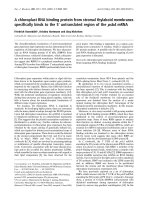
Step 5: Use coarse sandpaper glued to a straight stick as a disposable file to remove material up to the scribe line. Remove material that prevents the halves from matching smoothly. Take the time required to precision fit the wheel fairing halves. Assemble the U-00001A Wheel Fairing Front and U-00001B Wheel Fairing Aft and align the wheel hole openings. Tape them in this position and place a tape reference mark across the seam. Slit the tape on the seam with a razor blade and use this mark to realign the fairings during assembly.
<b>FIGURE 1: PREP FRONT FAIRING</b>
This section provides instruction for the installation of the left wheel only. The right side is a mirror of the left. <b>NOTE: Thefairings in this section must remain transparent to accomplish the installation. Do not sand or prime either side of thefairings until directed to do so or until installation is complete.</b>
The U-00001A Wheel Fairing Front and U-00001B Wheel Fairing Aft should mate as accurately as possible. Due to the variations in fiberglass molds it is necessary to first make the parts fit.
Step 1: The U-00001A Wheel Fairing Front has been laid up so that there are overlapping layers of cloth along its centerline. The area of overlap is thicker than the rest of the fairing. Sand down this thicker area so that at least 3/4 inch of the aft edge of the wheel fairing front is the same thickness all along its length.
Step 2: Trim the tire opening of the U-00001A Wheel Fairing Front to 1/16 inch from the scribe line with hand shears. Finish to the scribe line using a sanding block. See Figure 1.
LOCALLY REMOVE MATERIAL BUILDUP FOR PROPER FIT WITH WHEEL FAIRING AFT
CAREFULLY FIT FORWARD AND AFT FAIRING HALVES TO DETERMINE EDGE TRIM. FINISH TO SCRIBE LINE
<i><b>VAN'S AIRCRAFT, INC.</b></i>
09/21/16 <small>PAGE</small>
36A-02 RV-12
<small>REVISION:</small>0 <small>DATE:</small>Step 3: Square up the inside corner of molded step in the U-00001B Wheel Fairing Aft as required to allow for a good fit of the fairing halves as shown in Figure 2. A coarse file works well. Trim the wheel fairing aft flange to 3/4 inch from the molded step as shown in Figure 2.
Step 4: Trim the tire opening of the U-00001B Wheel Fairing Aft to 1/16 inch from the scribe line with hand shears. See Figure 2.
<b>FIGURE 2: PREP REAR FAIRING</b>
</div><span class="text_page_counter">Trang 3</span><div class="page_container" data-page="3">Step 4: Drill #30 the two dimples on each side of the U-00001A Wheel Fairing Front and U-00001B Wheel Fairing Aft as called-out in Figure 3.
<b>FIGURE 3: JOIN FAIRING HALVES & MATCH-DRILL</b>
Step 3: Join the U-00001A Wheel Fairing Front and U-00001B Wheel Fairing Aft as shown in Figure 3. Align the parts until they are fitting as well as possible then use several strips of tape to hold them together.
Using a #40 bit, match-drill the wheel fairing front to the wheel fairing aft at each of the nine "dimples" that are molded into the circumference of the wheel fairing front where it overlaps the wheel fairing aft. Cleco each drilled hole before drilling the next. Begin match-drilling at the top-center and work downward, alternating side-to-side until all nine dimples have been drilled. Hold the drill bit perpendicular to the surface of the wheel fairing halves while match-drilling.
Be aware of debris between parts as drilling progresses. Take apart and clean-out as necessary. Step 1: Check the length of each U-00002 Wheel Fairing Bracket for curve. If the part is curved, straighten as shown in Figure 1.
SURFACE SHOULD BE FLAT BETWEEN THESE ARROWS U-00002
<b>FIGURE 1: STRAIGHTENING</b>
THE WHEEL FAIRING BRACKETS
<b>NOTE: Use a bright light shining through the opposite side of the U-00001A Wheel Fairing Front and U-00001B WheelFairing Aft to align the holes and dimples in the following step.</b>
Step 2: With the U-00001A Wheel Fairing Front and U-00001B Wheel Fairing Aft joined, place a U-00002 Wheel Fairing Bracket flush on the interior surface of the wheel fairings. Align the holes in the wheel fairing bracket with the dimples in the wheel fairings. Check alignment on both sides of the wheel fairing halves. If required, sand the wheel fairing front's aft edge until the holes and dimples align properly. See Figure 2.
<i><b>VAN'S AIRCRAFT, INC.</b></i>
<small>DATE:</small>09/21/16 <small>REVISION:</small>0
RV-12
<small>PAGE</small>36A-03
</div><span class="text_page_counter">Trang 4</span><div class="page_container" data-page="4"><b>FIGURE 1:</b>
GEAR LEG CLEARANCE HOLE
Step 1: Use a fine point felt pen to mark gear leg opening on the U-00001A Wheel Fairing Front and U-00001B Wheel Fairing Aft as shown in Figure 1. Trim to within 1/16 of trim line then sand to finish edge.
Add a radius to wheel fairing aft for brake line clearance as shown in Figure 1. TRIM RADIUS FOR
BRAKE LINE CLEARANCE U-00001B
FWD UP
<b>NOTE: Illustration shows left side installation only, when modifying the right wheel fairings makethe cutout on the opposite side of the fairings.</b>
<small>REVISION:DATE:PAGEREVISION:DATE:</small>
<i><b>VAN'S AIRCRAFT, INC.</b></i>
09/21/16 <small>PAGE</small>
36A-04 RV-12
<small>REVISION:</small>0 <small>DATE:</small></div><span class="text_page_counter">Trang 5</span><div class="page_container" data-page="5"><b>NOTE: See Section 35 for information related to initialinstallation of the wheels and brakes. Specific details</b>
<b>pertaining to removal and reinstallation of wheels and brakeswill not be repeated in this section.</b>
Step 2: Remove the Main Wheel from the Axle.
Remove the bolts that attach the axle and Brake Plate to the U-1220-L Main Gear Leg.
Discard the two washers that were installed under each axle attach bolt head and reinstall the axle, brake plate, and U-00003 Bracket Mount to the main gear leg. The two holes in the axle must be horizontally aligned when installed as shown in Figure 2. Step 3: Attach one of the U-00002 Wheel Fairing Brackets to the U-00003 Bracket Mount as shown in Figure 3.
Reinstall the Main Wheel to the Axle. Step 1: Final-Drill #40 all the 3/32 holes in the 4 U-00002 Wheel Fairing Brackets. See Figure 1.
Machine countersink all the #40 holes in the wheel fairing brackets to fit the head of an AN426AD3 rivet. See Figure 1. Attach nutplates to the wheel fairing brackets using the rivets called-out in Figure 1.
<i><b>VAN'S AIRCRAFT, INC.</b></i>
<small>DATE:</small>09/21/16 <small>REVISION:</small>0
RV-12
<small>PAGE</small>36A-05
</div><span class="text_page_counter">Trang 6</span><div class="page_container" data-page="6"><b>FIGURE 2:</b>
MODIFYING WHEEL FAIRING HALVES
<b>FIGURE 1:</b>
ATTACH BRACKET MOUNT AND WHEEL FAIRING BRACKET
Step 1: Attach the U-00004 Bracket Mount andU-00002 Wheel Fairing Bracket to the axle with the hardware called out in Figure 1.
<b>NOTE: brake line may be gently re-formed by hand to fit inside wheel fairing.</b>
Step 2: Cleco the U-00001B Wheel Fairing Aft on the U-00002 Wheel Fairing Brackets. The clearance on the inboard and outboard side of the wheel opening are different; the inboard clearance is approximately 1/2 inch.
Step 3: With a fine point pen, mark the U-00001B Wheel Fairing Aft along the aft and outboard wheel opening so that the distance is the same as that of the inboard wheel opening. See Figure 2.
Remove the wheel fairing aft and trim to within 1/16 inch of the trim line. Finish to the trim line by sanding. Reinstall the wheel fairing aft on the U-00002 Wheel Fairing Brackets.
Step 4: Cleco the U-00001A Wheel Fairing Front to the U-00002 Wheel Fairing Brackets and the U-00001B Wheel Fairing Aft as shown in Figure 2.
Use a fine point pen to mark the wheel fairing front on the outboard side where it meets the wheel fairing aft wheel opening. Continue marking along the outboard side and front of the wheel opening to create the approximately 1/2 inch wheel clearance. Remove the wheel fairing front and trim to within 1/16 inch of the trim line. Finish to the trim line by sanding. Reinstall wheel fairing front and check that the wheel openings allow proper tire clearance. See Figure 2. <small>PAGEREVISION:DATE:</small>
<i><b>VAN'S AIRCRAFT, INC.</b></i>
09/21/16 <small>PAGE</small>
36A-06 RV-12
<small>REVISION:</small>0 <small>DATE:</small></div><span class="text_page_counter">Trang 7</span><div class="page_container" data-page="7"><b>NOTE: To locate the nutplate rivet holes the nutplate is held in</b>
<b>place with a mounting screw and the nutplate is used as a drill templateCleco the first rivet hole to prevent the nutplate from rotating whilelocating the second rivet hole. It is important on curved surfaces that</b>
<b>the nutplate is match-drilled from the side of the part on which it will later be installed.</b>
<b>NOTE: Machine countersinks into fiberglass that are up to .005 too shallow are acceptable , even preferable, tocountersinks which are too deep. Rivets should be slightly under set where installed in fiberglass parts.</b>
Step 4: Install nutplates at the three #27 holes drilled in Step 4. Final-Drill #40 and countersink the U-00001B Wheel Fairing Aft for nutplate rivets as shown in Figure 1. Deburr the holes. Rivet the nutplates to the wheel fairing aft as per the callouts.
Step 5: Reassemble the U-00001A Wheel Fairing Front and U-00001B Wheel Fairing Aft using three #6 screws and clecos at the rest of the holes. Final-Drill #27 the remainder of the #40 holes. Disassemble the wheel fairing halves. Install the remaining nutplates.
Countersink the #27 holes in the wheel fairing front as per the callout in Figure 2.
Step 6: Mount the U-00001B Wheel Fairing Aft and U-00001A Wheel Fairing Front to the U-00002 Wheel Fairing Brackets using the hardware called out in Figure 2. Use the screws called out in Figure 2 to attach the wheel fairing halves together.
Step 1: Final-drill #19 the U-00001B Wheel Fairing Aft and the U-00001A Wheel Fairing Front to the U-00002 Wheel Fairing Brackets. Avoid drilling into the nutplates mounted on the wheel fairing brackets. See Figure 1. Remove clecos and wheel fairings.
Step 2: Aggressively roughen the inside of the U-00001A Wheel Fairing Front and U-00001B Wheel Fairing Aft at the #19 screw locations. Clean.
Coat the threads of the 8-32 screws (called out in Figure 2) with wax to prevent epoxy from bonding to them. Tape the U-00002 Wheel Fairing Bracket tabs to prevent the epoxy/flox mixture from bonding to them.
Mix epoxy and flox (cotton or glass) to the consistency of peanut butter and build up the areas around the four screws on both the forward and aft main wheel fairings. Apply enough epoxy mixture (approximately 1/16 of an inch) to create a recess when the brackets are pressed against them, but not so much that the epoxy will capture the brackets. See Figure 1 Section A-A. Attach the wheel fairings to the brackets and to each other while the mixture is wet. Do not tighten the screws. Leave 1/16 protruding above the surface of the fairing.
Final-Drill #19 the screw holes again to remove any flox mixture.
Step 3: Final-Drill #27 three (of the nine) evenly spaced #40 screw attach holes in the U-00001A Wheel Fairing Front and U-00001B Wheel Fairing Aft as shown in Figure 1.
Remove the wheel fairing front and wheel fairing aft when the epoxy has fully cured.
<b>FIGURE 1:</b>
ATTACH WHEEL FAIRINGS TO WHEEL FAIRING BRACKETS
<i><b>VAN'S AIRCRAFT, INC.</b></i>
<small>DATE:</small>09/21/16 <small>REVISION:</small>0
RV-12
<small>PAGE</small>36A-07
</div><span class="text_page_counter">Trang 8</span><div class="page_container" data-page="8">Step 4: Remove the hatched area from the U-00006A-1 Wheel Fairing Bracket to create the U-00006A-L-1 and U-00006A-R-1 Wheel Fairing Brackets as shown in Figure 2.
<b>FIGURE 1: TRIMMING WHEEL FAIRING HALVES</b>
Check the inside of the wheel fairing front and aft in the areas where the parts are dimpled by running a finger over the interior surface. If there are thick spots, or bumps in the fiberglass, sand them down to make a uniform surface.
Step 2: Drill #40 the dimples in the U-00005A Wheel Fairing Front in six places as shown in Figure 1. Take care that the drill is held perpendicular to the surface.
Step 3: Holding the drill perpendicular to the surface, drill #40 the dimples in the U-00005B Wheel Fairing Aft as shown in Figure 1.
Step 5: Bend the U-00006B Splice Strips so that they fit the interior shape of the U-00005A Wheel Fairing Front. A close fit is desired. See Figure 3.
Step 6: Cleco the U-00006B Splice Strips to the inside of the U-00005A Wheel Fairing Front as shown in Figure 3. Match-Drill #40 and cleco the rivet attach holes between the nose wheel fairing and the splice strip. Clean debris as required.
Machine countersink holes in the wheel fairing front for the head of an AN426AD3 rivet.
<b>NOTE: Use a 1 inch step drill (if available) to finish the 3/4 holes drilled in Step 1.</b>
Step 7: Finish the holes drilled in the U-00005A Wheel Fairing Front in Step 1 to the finish diameter shown in Figure 3.
<b>FIGURE 2: WHEEL FAIRING</b>
Step 1: Remove material up to the scribe lines on both the U-00005A Wheel Fairing Front and U-00005B Wheel Fairing Aft.
Use a 3/4 inch step drill to remove the hatched areas on each side of the wheel fairing front. Center the drill on the dimples as
<b>FIGURE 3: FITTING SPLICE STRIPS</b>
AND WHEEL FAIRING FRONT
<i><b>VAN'S AIRCRAFT, INC.</b></i>
</div><span class="text_page_counter">Trang 9</span><div class="page_container" data-page="9">Step 1: Cleco the U-00005B Wheel Fairing Aft to the U-00006B Splice Strips and check fit. The parts fit together well when there is no strain or interference between the parts.
With the wheel fairing halves and splice strips clecoed together from the inside, the parts may be repositioned slightly. Make any additional adjustments to the fit by sanding the edges of the wheel fairing and forming the splice strips with smooth jawed and/or fluting pliers. See Figure 1.
Step 2: Final-Drill #19 the #40 holes in the U-00005B Wheel Fairing Aft to the U-00006B Splice Strips as shown in Figure 1. Secure the drilled holes with 8-32 screws and nuts to prevent the parts from shifting while drilling.
Match-Drill #19 the two top holes in the wheel fairing aft from the holes in the splice strips. See Figure 1.
Step 3: Cleco U-00006A-1 Wheel Fairing Brackets to the U-00006B Splice Strips as shown in Figure 2. The forward flanges of the wheel fairing brackets need to be adjusted slightly by hand for a good fit.
Final-Drill #27 All screw hole locations between the splice strips and wheel fairing brackets.
Final-Drill #40 all remaining 3/32 hole locations in the splice strips and wheel fairing brackets. Remove wheel fairing brackets. Dimple all nutplate attachment hole locations and the rivet hole locations common to the splice strips and the wheel fairing brackets. Dimple rivet holes in the corresponding nutplates. See Figures 1 and 2.
Step 4: With the U-00006B Splice Strips still clecoed to the U-00005A Wheel Fairing Front, carefully apply masking tape to the splice strip, following the edge of the nose wheel fairing front. Tape the entire length of the intersection between the parts. Step 5: Remove the clecoes and the U-00006B Splice Strips. Aggressively roughen the surface area on each part where the two overlap with 80 grit sandpaper. Leaving the tape in place, clean the parts.
Mix epoxy and flox (cotton or glass) to the consistency of peanut butter and smear a thin coating along the roughened surface of the U-00006B Splice Strips.
Step 6: While the epoxy mixture is still wet, cleco then rivet the U-00006B Splice Strips to the U-00005A Wheel Fairing Front with the rivets called out in Figure 1.
With a popsicle stick, remove any excess epoxy mixture that has squeezed out between the parts. Remove masking tape. Allow epoxy to cure.
U-00006A-L-1 U-00006A-R-1
<b>FIGURE 2: RIVETING WHEEL FAIRING BRACKETS</b>
AND NUTPLATES TO THE WHEEL FAIRING FRONT
<b>FIGURE 1: RIVETING SPLICE STRIPS TO THE WHEEL FAIRING FRONT</b>
<b>NOTE: Nutplates installed in tight radius areas will fitbetter if pre-bent.</b>
Step 7: Cleco then rivet the U-00006A-1 Wheel Fairing Brackets to the U-00006B Splice Strips. Install the nutplates called out in Figure 2.
APPLY MASKING TAPE TO THE SPLICE PLATE ALONG THIS INTERSECTION
<i><b>VAN'S AIRCRAFT, INC.</b></i>
<small>DATE:</small>09/21/16 <small>REVISION:</small>0
RV-12
<small>PAGE</small>36A-09
</div><span class="text_page_counter">Trang 10</span><div class="page_container" data-page="10">Step 1: Secure the U-00006C-1 Drill Template to the
U-00006A-L-1 and U-00006A-R-1 Wheel Fairing Brackets with #8 screws and nuts as shown in Figure 1.
<b>FIGURE 1: POSITIONING THE DRILL TEMPLATE</b>
Step 2: Attach the U-00005B Wheel Fairing Aft to the U-00006B Splice Strips. Clamp the drill template to the wheel fairing brackets. Use a fine point felt pen to mark the drill template along the intersection between the drill template and the wheel fairing brackets. See Figure 2.
Remove the nose wheel fairing aft.
Step 3: Check that the drill template is still aligned properly with the wheel fairing brackets by checking the alignment marks made in Step 2. Match-Drill #19 the drill template to the wheel fairing brackets. See Figure 1.
Remove the drill template and deburr the wheel fairing brackets.
<i><b>VAN'S AIRCRAFT, INC.</b></i>
<b>FIGURE 3: INSTALLING THE DOUBLER PLATES</b>
Step 4: Secure the U-00006D-1 Doubler Plates to the wheel fairing brackets with #8 screws and nuts as shown for the U-00006A-R-1 in Figure 3. Match-Drill #40 the doubler plates to the wheel fairing brackets.
Disassemble and deburr. Dimple all #40 rivet holes in the wheel fairing brackets.
Machine countersink the doubler plates to fit the dimples in the brackets.
Rivet the doubler plates to the wheel fairing brackets using the rivets called out in Figure 3.
</div>