MODEL 10 SERIES B PLANETARY GEAR DRIVE
Bạn đang xem bản rút gọn của tài liệu. Xem và tải ngay bản đầy đủ của tài liệu tại đây (1.17 MB, 12 trang )
<span class="text_page_counter">Trang 1</span><div class="page_container" data-page="1">
<small>Auburn, Indiana 46706-3499 • USA</small>
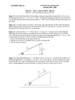
Planetary Gear Drive
Planetary Gear Drive
</div><span class="text_page_counter">Trang 2</span><div class="page_container" data-page="2"><b>MODEL 10 SERIES BFEATURES</b>
Seller warrants to Purchaser that its Power Wheel<small>®</small> planetary gear products are free from defects in material and workmanship under normal use and service for a period of one year from the date the product is shown to have been placed into operation by original user or for two years from date of shipment from seller’s plant, whichever shall first occur.
Seller’s obligation under this warranty is expressly limited to the repair or replacement at its option, of the Power Wheel which is returned with a written claim of defect f.o.b. seller’s factory, Auburn, Indiana, U.S.A., and which is determined by Seller to be defective in fact.
THIS IS THE SOLE AND ONLY WARRANTY OF SELLER AND NO OTHER WARRANTY IS AP-PLICABLE, EITHER EXPRESSED OR IMPLIED, IN FACT OR BY LAW, INCLUDING ANY WARRANTY AS TO MERCHANTABILITY OR FITNESS FOR A PARTICULAR USE OR PURPOSE.
The sole and only remedy in regard to any de-fective Power Wheel shall be the repair or replace-ment thereof herein provided, and seller shall not be liable for any consequential, special, incidental, or punitive damages, losses or expenses resulting from or caused by any defects.
AUBURN GEAR, INC. AUBURN, INDIANA, U.S.A.
Warranty
<b>WARRANTY INFORMATION</b>
Auburn Gear is your reliable source for a variety of power transfer products. This catalog features the Model 10 Series B family of Power Wheel<b><small>®</small> Planetary Gear Drives. Other models of Power Wheels are also available; for a complete offering, contact </b>
Auburn Gear.
We also offer planetary gear kits and limited-slip differentials. We offer you services for design, engineering, prototype support and full testing and production capabilities. Product applications include access, agricultural, automotive, construction, forestry, industrial and marine. Auburn Gear offers you quality and reliability backed by more than 60 years of experience.
<b> Greater Design Flexibility</b>
Power Wheel<b><small>®</small></b> planetary drives allow greater flexibility than conventional power train systems and often eliminate the need for components such as drive shafts, axles and chain drives. The many models and styles offered meet a wide range of mobile and industrial application requirements. Single, double and triple reduction ratios can be furnished. In addition, they can be supplied with a variety of motor mounts and inputs which allow them to be used with most makes of hydraulic motors.
<b> High Efficiency and Compact Design</b>
Providing 94 to 98% power transfer efficiency, Power Wheel<b><small>®</small></b>
planetary drives are significantly more efficient than many other types of drives, including differential design planetaries. The rug-ged, compact design of these drives saves space and provides for long service life.
All models can be furnished with parking brakes. Auburn Gear has designed integral parking brakes in Models 40, 5, 6, 6B, 60, 7, 75, 8, 8B and 9. These units provide a very compact planetary drive/parking brake package which is particularly useful in applications where space is limited.
<b> Responsive Performance</b>
Power Wheel<b><small>®</small></b> drives deliver the power you require for smooth operation and precise control. These units are also fully revers-ible. Reverse power is easily obtained by reversing rotation of the input. For vehicle applications, the positive traction provided by individually powered wheels results in superior maneuverability and improved ground clearance than conventional drive systems.
Auburn Gear Power Wheel drives can be an efficient solution for any application where you need to increase torque or reduce speed to achieve usable power. Let Power Wheel<b><small>®</small></b> planetary drives help you put power in its place.
<i><b><small>All specifications and data contained herein are nominal and subject to change without notice.Specific applications should be referred to Auburn Gear for current information.</small></b></i>
</div><span class="text_page_counter">Trang 3</span><div class="page_container" data-page="3">Seller warrants to Purchaser that its Power Wheel<small>®</small> planetary gear products are free from defects in material and workmanship under normal use and service for a period of one year from the date the product is shown to have been placed into operation by original user or for two years from date of shipment from seller’s plant, whichever shall first occur.
Seller’s obligation under this warranty is expressly limited to the repair or replacement at its option, of the Power Wheel which is returned with a written claim of defect f.o.b. seller’s factory, Auburn, Indiana, U.S.A., and which is determined by Seller to be defective in fact.
THIS IS THE SOLE AND ONLY WARRANTY OF SELLER AND NO OTHER WARRANTY IS AP-PLICABLE, EITHER EXPRESSED OR IMPLIED, IN FACT OR BY LAW, INCLUDING ANY WARRANTY AS TO MERCHANTABILITY OR FITNESS FOR A PARTICULAR USE OR PURPOSE.
The sole and only remedy in regard to any de-fective Power Wheel shall be the repair or replace-ment thereof herein provided, and seller shall not be liable for any consequential, special, incidental, or punitive damages, losses or expenses resulting from or caused by any defects.
AUBURN GEAR, INC. AUBURN, INDIANA, U.S.A.
Warranty
<b>WARRANTY INFORMATION</b>
Auburn Gear is your reliable source for a variety of power transfer products. This catalog features the Model 10 Series B family of Power Wheel<b><small>®</small> Planetary Gear Drives. Other models of Power Wheels are also available; for a complete offering, contact </b>
Auburn Gear.
We also offer planetary gear kits and limited-slip differentials. We offer you services for design, engineering, prototype support and full testing and production capabilities. Product applications include access, agricultural, automotive, construction, forestry, industrial and marine. Auburn Gear offers you quality and reliability backed by more than 60 years of experience.
<b> Greater Design Flexibility</b>
Power Wheel<b><small>®</small></b> planetary drives allow greater flexibility than conventional power train systems and often eliminate the need for components such as drive shafts, axles and chain drives. The many models and styles offered meet a wide range of mobile and industrial application requirements. Single, double and triple reduction ratios can be furnished. In addition, they can be supplied with a variety of motor mounts and inputs which allow them to be used with most makes of hydraulic motors.
<b> High Efficiency and Compact Design</b>
Providing 94 to 98% power transfer efficiency, Power Wheel<b><small>®</small></b>
planetary drives are significantly more efficient than many other types of drives, including differential design planetaries. The rug-ged, compact design of these drives saves space and provides for long service life.
All models can be furnished with parking brakes. Auburn Gear has designed integral parking brakes in Models 40, 5, 6, 6B, 60, 7, 75, 8, 8B and 9. These units provide a very compact planetary drive/parking brake package which is particularly useful in applications where space is limited.
<b> Responsive Performance</b>
Power Wheel<b><small>®</small></b> drives deliver the power you require for smooth operation and precise control. These units are also fully revers-ible. Reverse power is easily obtained by reversing rotation of the input. For vehicle applications, the positive traction provided by individually powered wheels results in superior maneuverability and improved ground clearance than conventional drive systems.
Auburn Gear Power Wheel drives can be an efficient solution for any application where you need to increase torque or reduce speed to achieve usable power. Let Power Wheel<b><small>®</small></b> planetary drives help you put power in its place.
<i><b><small>All specifications and data contained herein are nominal and subject to change without notice.Specific applications should be referred to Auburn Gear for current information.</small></b></i>
</div><span class="text_page_counter">Trang 4</span><div class="page_container" data-page="4">Max. intermittent output torque<small>1 </small>180,000 lb-in . (20,340 Nm)
Max. input speed ... 5,000 RPM
Approximate weight ... 375 lbs (170 kg) Oil capacity ... 96 oz (2,840 cc)
<small>1 Depending on the duty cycle and the nature of the application, a normal continuous output torque of 1/3 to 1/2 of the maximum Intermittent should yield satisfactory </small>
<i><small>Power Wheel life. Customer testing and application analysis is strongly recommended.</small></i>
<small>Dimensions given in: INCHES (mm)</small>
<b>Model 10 Series B Wheel Drives - Double Reduction</b>
<b>NON-POWERED UNITS ARE ALSO AVAILABLE - Contact Auburn Gear for InformationOPTIONAL PARKING BRAKES ARE ALSO AVAILABLE (See Page 11)</b>
<i><small>“O” Ring or Gasket required (not supplied by Auburn Gear)“O” Ring Size: SAE C 2-159</small></i>
<i>For Lubrication Data, see Page 11</i>
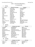
<b><small>BEARING LOAD, LIFE AND SPEED RELATIONSHIPS</small></b>
<b><small>SF x RR’LF =</small></b>
<b><small> R = Allowable resultant load for given location from mounting flangeR’ = Anticipated load at location from mounting flange</small></b>
<i><b><small>LF = Life Factor from table (see below)SF = Speed Factor from table (see below)</small></b></i>
<b><small>CAUTION: The same torsional loading constraints used in the driving mode must </small></b>
<small>be used in the braking mode when braking through the Power Wheel drive gear set.</small>
<b><small>The data presented in this catalog is for general information and preliminary layout purposes only. Auburn Gear, through its policy of continual improvement, reserves the right to update its products; therefore, the information presented is subject to change. For specific application and/or dimen-sional information, contact Auburn Gear.</small></b>
<small>BOLDFACE INDICATES REGULAR VOLUME PRODUCED ITEMS WITH BEST AVAILABILITY.</small>
<b>MODEL 10 WHEEL DRIVES - DOUBLE REDUCTION </b>
<small>Pipe Plugs Spindle Side High Strength Carrier </small><b><small>MAKE ALL SELECTIONS </small></b>
<b><small>USE OPTION ORDER CODES TO BUILD ORDER NUMBER </small></b>
<small>Select desired characteristics from chart, note correct order codes, and order using sample format shown at right:</small>
<small>DISTANCE FROM MOUNTING FACETO RADIAL LOAD (INCHES)</small>
<small>WHEEL MOUNTING FLANGE</small>
<b><small>NOTE: </small></b>
<small>These curves are supplied as a design guide and apply to resultant radial load only. They indicate the importance of maintaining wheel position over the bearing center.</small>
<small>For actual analysis, applications should be reviewed by Auburn Gear Engineering using data supplied on Application Data Form. </small>
<b>GENERAL SPECIFICATIONS</b>
</div><span class="text_page_counter">Trang 5</span><div class="page_container" data-page="5">Max. intermittent output torque<small>1 </small>180,000 lb-in . (20,340 Nm)
Max. input speed ... 5,000 RPM
Approximate weight ... 375 lbs (170 kg) Oil capacity ... 96 oz (2,840 cc)
<small>1 Depending on the duty cycle and the nature of the application, a normal continuous output torque of 1/3 to 1/2 of the maximum Intermittent should yield satisfactory </small>
<i><small>Power Wheel life. Customer testing and application analysis is strongly recommended.</small></i>
<small>Dimensions given in: INCHES (mm)</small>
<b>Model 10 Series B Wheel Drives - Double Reduction</b>
<b>NON-POWERED UNITS ARE ALSO AVAILABLE - Contact Auburn Gear for InformationOPTIONAL PARKING BRAKES ARE ALSO AVAILABLE (See Page 11)</b>
<i><small>“O” Ring or Gasket required (not supplied by Auburn Gear)“O” Ring Size: SAE C 2-159</small></i>
<i>For Lubrication Data, see Page 11</i>
<b><small>BEARING LOAD, LIFE AND SPEED RELATIONSHIPS</small></b>
<b><small>SF x RR’LF =</small></b>
<b><small> R = Allowable resultant load for given location from mounting flangeR’ = Anticipated load at location from mounting flange</small></b>
<i><b><small>LF = Life Factor from table (see below)SF = Speed Factor from table (see below)</small></b></i>
<b><small>CAUTION: The same torsional loading constraints used in the driving mode must </small></b>
<small>be used in the braking mode when braking through the Power Wheel drive gear set.</small>
<b><small>The data presented in this catalog is for general information and preliminary layout purposes only. Auburn Gear, through its policy of continual improvement, reserves the right to update its products; therefore, the information presented is subject to change. For specific application and/or dimen-sional information, contact Auburn Gear.</small></b>
<small>BOLDFACE INDICATES REGULAR VOLUME PRODUCED ITEMS WITH BEST AVAILABILITY.</small>
<b>MODEL 10 WHEEL DRIVES - DOUBLE REDUCTION </b>
<small>Pipe Plugs Spindle Side High Strength Carrier </small><b><small>MAKE ALL SELECTIONS </small></b>
<b><small>USE OPTION ORDER CODES TO BUILD ORDER NUMBER </small></b>
<small>Select desired characteristics from chart, note correct order codes, and order using sample format shown at right:</small>
<small>DISTANCE FROM MOUNTING FACETO RADIAL LOAD (INCHES)</small>
<small>WHEEL MOUNTING FLANGE</small>
<b><small>NOTE: </small></b>
<small>These curves are supplied as a design guide and apply to resultant radial load only. They indicate the importance of maintaining wheel position over the bearing center.</small>
<small>For actual analysis, applications should be reviewed by Auburn Gear Engineering using data supplied on Application Data Form. </small>
<b>GENERAL SPECIFICATIONS</b>
</div><span class="text_page_counter">Trang 6</span><div class="page_container" data-page="6"><small>*Spacer plate required when 52.35:1 ratio is used</small>
<i><small>with any “A” mount and the 14T input spline.</small></i>
<small>Spacer adds .600 (15.24) to overall length of drive</small>
<small>These curves are supplied as a design guide and apply to resultant radial load only. They indicate the importance of maintaining wheel position over the bearing center.</small>
<small>For actual analysis, applications should be reviewed by Auburn Gear Engineering using data supplied on Application Data Form. </small>
<b><small>BEARING LOAD, LIFE AND SPEED RELATIONSHIPS</small></b>
<b><small>SF x RR’LF =</small></b>
<b><small> R = Allowable resultant load for given location from mounting flangeR’ = Anticipated load at location from mounting flange</small></b>
<i><b><small>LF = Life Factor from table (see below)SF = Speed Factor from table (see below)</small></b></i>
<b><small>CAUTION: The same torsional loading constraints used in the driving mode must </small></b>
<small>be used in the braking mode when braking through the Power Wheel drive gear set.</small>
<small>The data presented in this catalog is for general information and preliminary layout purposes only. Auburn Gear, through its policy of continual improvement, reserves the right to update its prod-ucts; therefore, the information presented is subject to change. For specific application and/or dimensional information, contact Auburn Gear.</small>
<b>Model 10 Series B Shaft </b>
<b>Output Drives - Double Reduction</b>
<small>1 Depending on the duty cycle and the nature of the application, a normal continuous output torque of 1/3 to 1/2 of the Maximum Intermittent should yield satisfactory </small>
<i><small>Power Wheel life. Customer testing and application analysis is strongly recommended.</small></i>
<small>Dimensions given in: INCHES (mm)</small>
Max. intermittent output torque<small>1 </small>180,000 lb-in (20,340 Nm) Max. input speed ... 5,000 RPM
Approximate weight ... 300 lbs (136 kg) Oil capacity ... 96 oz (2,840 cc)
<i>For Lubrication Data, see Page 11</i>
<b>OPTIONAL PARKING BRAKES ARE ALSO AVAILABLE (See Page 11)</b>
<small>BOLDFACE INDICATES REGULAR VOLUME PRODUCED ITEMS WITH BEST AVAILABILITY.</small>
<b>MODEL 10 SHAFT OUTPUT DRIVES - DOUBLE REDUCTION</b>
<b><small>USE OPTION ORDER CODES TO BUILD ORDER NUMBER ORDER </small></b>
<small>Select desired characteristics from chart, note correct order codes, and order using sample format shown at right:</small>
<b><small>MAKE ALL CHOICES </small></b>
<small>* Spacer plate required when 52.35:1 ratio is used with any “A” mount and the 14T input spline.</small>
<b>MOTOR MOUNTING CHART</b>
<small>: “O” RING OR GASKET REQUIRED (Not Supplied by Auburn Gear) “O” RING SIZES: SAE “A” 2–042, SAE “B” 2–155, SAE “C” 2–159</small>
<b><small>MOTOR MOUNTING HOLE DIMENSIONSSAE A, A1, A2 (2) – .500 (12.70) -13 UNC - 2B </small></b>
<small>Holes Equally Spaced on 4.187 (106.35) B. C.</small>
<b><small>SAE B (2) – .500 (12.70) -13 UNC - 2B Holes </small></b>
</div><span class="text_page_counter">Trang 7</span><div class="page_container" data-page="7"><small>*Spacer plate required when 52.35:1 ratio is used</small>
<i><small>with any “A” mount and the 14T input spline.</small></i>
<small>Spacer adds .600 (15.24) to overall length of drive</small>
<small>These curves are supplied as a design guide and apply to resultant radial load only. They indicate the importance of maintaining wheel position over the bearing center.</small>
<small>For actual analysis, applications should be reviewed by Auburn Gear Engineering using data supplied on Application Data Form. </small>
<b><small>BEARING LOAD, LIFE AND SPEED RELATIONSHIPS</small></b>
<b><small>SF x RR’LF =</small></b>
<b><small> R = Allowable resultant load for given location from mounting flangeR’ = Anticipated load at location from mounting flange</small></b>
<i><b><small>LF = Life Factor from table (see below)SF = Speed Factor from table (see below)</small></b></i>
<b><small>CAUTION: The same torsional loading constraints used in the driving mode must </small></b>
<small>be used in the braking mode when braking through the Power Wheel drive gear set.</small>
<small>The data presented in this catalog is for general information and preliminary layout purposes only. Auburn Gear, through its policy of continual improvement, reserves the right to update its prod-ucts; therefore, the information presented is subject to change. For specific application and/or dimensional information, contact Auburn Gear.</small>
<b>Model 10 Series B Shaft </b>
<b>Output Drives - Double Reduction</b>
<small>1 Depending on the duty cycle and the nature of the application, a normal continuous output torque of 1/3 to 1/2 of the Maximum Intermittent should yield satisfactory </small>
<i><small>Power Wheel life. Customer testing and application analysis is strongly recommended.</small></i>
<small>Dimensions given in: INCHES (mm)</small>
Max. intermittent output torque<small>1 </small>180,000 lb-in (20,340 Nm) Max. input speed ... 5,000 RPM
Approximate weight ... 300 lbs (136 kg) Oil capacity ... 96 oz (2,840 cc)
<i>For Lubrication Data, see Page 11</i>
<b>OPTIONAL PARKING BRAKES ARE ALSO AVAILABLE (See Page 11)</b>
<small>BOLDFACE INDICATES REGULAR VOLUME PRODUCED ITEMS WITH BEST AVAILABILITY.</small>
<b>MODEL 10 SHAFT OUTPUT DRIVES - DOUBLE REDUCTION</b>
<b><small>USE OPTION ORDER CODES TO BUILD ORDER NUMBER ORDER </small></b>
<small>Select desired characteristics from chart, note correct order codes, and order using sample format shown at right:</small>
<b><small>MAKE ALL CHOICES </small></b>
<small>* Spacer plate required when 52.35:1 ratio is used with any “A” mount and the 14T input spline.</small>
<b>MOTOR MOUNTING CHART</b>
<small>: “O” RING OR GASKET REQUIRED (Not Supplied by Auburn Gear) “O” RING SIZES: SAE “A” 2–042, SAE “B” 2–155, SAE “C” 2–159</small>
<b><small>MOTOR MOUNTING HOLE DIMENSIONSSAE A, A1, A2 (2) – .500 (12.70) -13 UNC - 2B </small></b>
<small>Holes Equally Spaced on 4.187 (106.35) B. C.</small>
<b><small>SAE B (2) – .500 (12.70) -13 UNC - 2B Holes </small></b>
</div><span class="text_page_counter">Trang 8</span><div class="page_container" data-page="8"><i><small>*Spacer plate required when 52.35:1 ratio is used with any “A” mount and the 14T input spline.</small></i>
<small>Spacer adds .600 (15.24) to overall length of drive</small>
<small>These curves are supplied as a design guide and apply to resultant radial load only. They indicate the importance of maintaining load position over the bearing center.</small>
<small>For actual analysis, applications should be reviewed by Auburn Gear Engineering using data supplied on Application Data Form. </small>
<b><small>BEARING LOAD, LIFE AND SPEED RELATIONSHIPS</small></b>
<b><small>SF x RR’LF =</small></b>
<b><small> R = Allowable resultant load for given location from mounting flangeR’ = Anticipated load at location from mounting flange</small></b>
<i><b><small>LF = Life Factor from table (see below)SF = Speed Factor from table (see below)</small></b></i>
<b><small>CAUTION: The same torsional loading constraints used in the driving mode must </small></b>
<small>be used in the braking mode when braking through the Power Wheel drive gear set.</small>
<small>The data presented in this catalog is for general information and preliminary layout purposes only. Auburn Gear, through its policy of continual improvement, reserves the right to update its prod-ucts; therefore, the information presented is subject to change. For specific application and/or dimensional information, contact Auburn Gear.</small>
<small>Dimensions given in: INCHES (mm)</small>
Max. intermittent output torque<small>1 </small>180,000 lb-in (20,340 Nm) Max. input speed ... 5,000 RPM
Approximate weight ... 340 lbs (154 kg) Oil capacity ... 96 oz (2,840 cc)
<i>For Lubrication Data, see Page 11</i>
<small>1 Depending on the duty cycle and the nature of the application, a normal continuous output torque of 1/3 to 1/2 of the maximum Intermittent should yield satisfactory </small>
<i><small>Power Wheel life. Customer testing and application analysis is strongly recommended.</small></i>
<b>Model 10 Series B Spindle </b>
<b>Output Drives - Double Reduction</b>
<small>BOLDFACE INDICATES REGULAR VOLUME PRODUCED ITEMS WITH BEST AVAILABILITY.</small>
<b>MODEL 10 SPINDLE OUTPUT DRIVES - DOUBLE REDUCTION<small>MAKE ALL CHOICES </small></b> <small>Select desired characteristics from chart, note correct order codes, and </small>
<small>order using sample format shown at right:</small> <b><small> 0S3C2 14 52 F1 Z</small></b>
<small>* Spacer plate required when 52.35:1 ratio is used with any “A” mount and the 14T input spline.</small>
<small>** Guard available only with SAE A, B, C configurations</small>
<small>DISTANCE FROM MOUNTING FACE TO RADIAL LOAD – IN (MM)</small>
<b>MOTOR MOUNTING CHART</b>
<small> “O” RING SIZES: SAE “A” 2–042, SAE “B” 2–155, SAE “C” 2–159</small> <b><small>MOTOR MOUNTING HOLE DIMENSIONS</small></b>
<b><small>SAE A, A1, A2 (2) – .500 (12.70) -13 UNC </small></b>
<small>- 2B Holes Equally Spaced on 4.187 (106.35) B. C.</small>
<b><small>SAE B (2) – .500 (12.70) -13 UNC - 2B Holes </small></b>
</div><span class="text_page_counter">Trang 9</span><div class="page_container" data-page="9"><i><small>*Spacer plate required when 52.35:1 ratio is used with any “A” mount and the 14T input spline.</small></i>
<small>Spacer adds .600 (15.24) to overall length of drive</small>
<small>These curves are supplied as a design guide and apply to resultant radial load only. They indicate the importance of maintaining load position over the bearing center.</small>
<small>For actual analysis, applications should be reviewed by Auburn Gear Engineering using data supplied on Application Data Form. </small>
<b><small>BEARING LOAD, LIFE AND SPEED RELATIONSHIPS</small></b>
<b><small>SF x RR’LF =</small></b>
<b><small> R = Allowable resultant load for given location from mounting flangeR’ = Anticipated load at location from mounting flange</small></b>
<i><b><small>LF = Life Factor from table (see below)SF = Speed Factor from table (see below)</small></b></i>
<b><small>CAUTION: The same torsional loading constraints used in the driving mode must </small></b>
<small>be used in the braking mode when braking through the Power Wheel drive gear set.</small>
<small>The data presented in this catalog is for general information and preliminary layout purposes only. Auburn Gear, through its policy of continual improvement, reserves the right to update its prod-ucts; therefore, the information presented is subject to change. For specific application and/or dimensional information, contact Auburn Gear.</small>
<small>Dimensions given in: INCHES (mm)</small>
Max. intermittent output torque<small>1 </small>180,000 lb-in (20,340 Nm) Max. input speed ... 5,000 RPM
Approximate weight ... 340 lbs (154 kg) Oil capacity ... 96 oz (2,840 cc)
<i>For Lubrication Data, see Page 11</i>
<small>1 Depending on the duty cycle and the nature of the application, a normal continuous output torque of 1/3 to 1/2 of the maximum Intermittent should yield satisfactory </small>
<i><small>Power Wheel life. Customer testing and application analysis is strongly recommended.</small></i>
<b>Model 10 Series B Spindle </b>
<b>Output Drives - Double Reduction</b>
<small>BOLDFACE INDICATES REGULAR VOLUME PRODUCED ITEMS WITH BEST AVAILABILITY.</small>
<b>MODEL 10 SPINDLE OUTPUT DRIVES - DOUBLE REDUCTION<small>MAKE ALL CHOICES </small></b> <small>Select desired characteristics from chart, note correct order codes, and </small>
<small>order using sample format shown at right:</small> <b><small> 0S3C2 14 52 F1 Z</small></b>
<small>* Spacer plate required when 52.35:1 ratio is used with any “A” mount and the 14T input spline.</small>
<small>** Guard available only with SAE A, B, C configurations</small>
<small>DISTANCE FROM MOUNTING FACE TO RADIAL LOAD – IN (MM)</small>
<b>MOTOR MOUNTING CHART</b>
<small> “O” RING SIZES: SAE “A” 2–042, SAE “B” 2–155, SAE “C” 2–159</small> <b><small>MOTOR MOUNTING HOLE DIMENSIONS</small></b>
<b><small>SAE A, A1, A2 (2) – .500 (12.70) -13 UNC </small></b>
<small>- 2B Holes Equally Spaced on 4.187 (106.35) B. C.</small>
<b><small>SAE B (2) – .500 (12.70) -13 UNC - 2B Holes </small></b>
</div><span class="text_page_counter">Trang 10</span><div class="page_container" data-page="10"><small>External Involute Spline30 Flat Root-Side Fit perANSI Standard 92.1–1970 — Class 6 Fit</small>
<small>External Involute Spline30 Flat Root-Side Fit perANSI Standard 92.1–1970 — Class 5 Fit</small>
Maximum Operating Pressure ...3,000 psi (207 Bar) Pressure Spikes or Surges not to Exceed ...4,000 psi (276 Bar) Maximum Speed ...5,000 RPM Maximum Brake Cavity Cooling Oil Pressure ...15 psi (1 Bar) Oil Fill Volume ... 150cc - Horizontal, 300cc - Vertical Mounting Fluid Type ... Mineral Base Hydraulic Oil
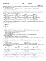
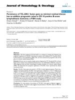
Model 10 drives (wheel, shaft, and spindle) can be supplied with an optional parking brake. The brakes are a bolt-on design, and have an SAE C 4-bolt motor mount. They operate wet and are intended for park-ing or holdpark-ing applications only. Three sizes are currently available. The torques and release pressures are shown at right, with the ordering code for each size. Note these brakes can be used for vertical and horizontal operation. Here is an example of an order code for a Model 10 with the parking brake option:
<i><b>TYPICAL MODEL SHOWN For detailed information on </b></i>
<i>other models, contact Auburn Gear</i>
<b>Boot Seal</b>
<small>An optional seal that protects the main oil seal from dirt and other de-bris. The boot seal will give extended life on applications operating in extremely muddy or dirty conditions. Boot seals are available on a selective model basis.</small>
<b>Weldable Hub</b>
<small>The hubs are 4140H steel and can be turned down and/or welded for mounting sprockets, pulleys, or other devices. A circular keeper plate secures the hub to the splined output shaft with two bolts (keeper plate and bolts included).</small>
<small>This optional disconnect is available on all wheel drives. No tools are needed to disengage or re-engage the drive. The planetary drive is disengaged with the push of a button. The quick disconnect eliminates removal of the disconnect cover and external contaminates are sealed from the units by internal o-rings and a gasket that is sandwiched between the disconnect and planetary cover. The rugged, compact design ensures dependable service.</small>
<b>Guard and Boot Seal System</b>
<small>A boot seal and metal guard are avail-able with the Model 10 SAE A, B and C configurations. These can be ordered separately or together. They function best together. The guard and boot seal system are utilized in extremely high grit applica-tions. The guard protects the boot seal from contaminants which will ultimately wear the boot seal lip.</small>
<b><small>Metal Guard</small></b>
<b><small>Boot Seal</small></b>
<small>Maximum Release Pressure (All Brake Models) = 3,000 PSI (207 Bar)A1 5,400 lb-in (610 Nm) 150 PSI (10.3 Bar)A2 7,200 lb-in (815 Nm) 190 PSI (13.0 Bar)A4 9,000 lb-in (1017 Nm) 230 PSI (16.3 Bar)</small>
<b>BRAKE RATINGS</b>
<small>Dimensions given in: INCHES (mm)</small>
<small>AGI recommends SAE 80W, 90, 80W-90 and 85W-90 grades of lube under normal climate and operating conditions. See chart below. For severe or abnormal applications with special requirements consult either Auburn Gear or a lubricant manufacturer for further assistance.</small>
<small>changes every 1000 hours or yearly whichever comes first.</small>
<small>Maximum intermittent temperature recommended is 200°F.</small>
<small>for other mounts will vary. Consult Auburn Gear for details.</small>
<small>special provisions apply to ensure adequate lubrication of output bearings. Consult Auburn Gear.</small>
<b>Auburn Gear Power Wheel Low Temperature Gear Lube Requirement</b>
<b>*</b><small> Maximum temperature for Brookfield Viscosity</small><b><sup>1</sup></b><small> of 150,000 centipoise (cP)</small><b><sup>2</sup></b><small> per SAE J306 MAR85</small>
<b><small>1 </small></b><i><sub>Brookfield Viscosity - apparent viscosity as determined under ASTM D 2983 </sub></i>
<b><small>2</small></b><sub> 150,000 cP determined to provide sufficient low temperature lube properties for Auburn Gear Power Wheels</sub>