Introduction to Microfluidics ppt
Bạn đang xem bản rút gọn của tài liệu. Xem và tải ngay bản đầy đủ của tài liệu tại đây (6.9 MB, 312 trang )
Introduction to Microfluidics
This page intentionally left blank
Introduction to
Microfluidics
Patrick Tabeling
ESPCI, Paris
translated by
Suelin Chen
MIT, Cambridge
Great Clarendon Street, Oxford OX2 6DP
Oxford University Press is a department of the University of Oxford.
It furthers the University’s objective of excellence in research, scholarship,
and education by publishing worldwide in
Oxford N ewYork
Auckland Cape Town Dar es Salaam Hong Kong Karachi
Kuala Lumpur Madrid Melbourne Mexico City Nairobi
New Delhi Shanghai Taipei Toronto
With offices in
Argentina Austria Brazil Chile Czech Republic France Greece
Guatemala Hungary Italy Japan Poland Portugal Singapore
South Korea Switzerland Thailand Turkey Ukraine Vietnam
Oxford is a registered trade mark of Oxford University Press
in the UK and in certain other countries
Published in the United States
by Oxford University Press Inc., New York
Édition originale: Introduction à la microfluidique © Éditions Belin- Paris 2003
English translation © Oxford University Press 2005
Aidé par le ministère français chargé de la culture
The moral rights of the author have been asserted
Database right Oxford University Press (maker)
First published in English 2005
All rights reser ved. No part of this publication may be reproduced,
stored in a retrieval system, or tr ansmitted, in any form or by any means,
without the prior permission in writing of Oxford University Press,
or as expressly permitted by law, or under terms agreed with the appropriate
reprographics rights organization. Enquiries concerning reproduction
outside the scope of the above should be sent to the Rights Department,
Oxford University Press, at the address above
You must not circulate this book in any other binding or cover
and you must impose the same condition on any acquirer
British Library Cataloguing in Publication Data
Data available
Library of Congress Cataloging-in-Publication Data
Tabeling, P.
[Introduction à la microfluidique. English]
Introduction to microfluidics / Patrick Tabeling ; translated by Suelin Chen.
p. cm.
Includes bibliographical references and index.
ISBN-13: 978–0–19–856864–3 (acid-free paper)
ISBN-10: 0–19–856864–9 (acid-free paper)
1. Fluidic devices. 2. Microfluidics. 3. Microelectromechanical systems. I. Title.
TJ853.T33 2005
629.8
042—dc22
2005019679
Typeset by Newgen Imaging Systems (P) Ltd., Chennai, India
Printed in Great Britain
on acid-free paper by
Ashford Colour Press, UK
ISBN 0–19–856864–9 978–0–19–856864–3
10987654321
Contents
ACKNOWLEDGEMENTS viii
Introduction 1
MEMS and microfluidics 1
The birth of microfluidics 8
Microfluidics and lab-on-a-chip devices 11
Microfluidics and chemical engineering 13
Astonishing microfluidic systems in nature 15
Different aspects of microfluidics 16
Possibilities offered by nanofluidics 18
Specialized publications 18
Organization of the text 19
Perspectives on microfluidics 21
References 21
1 Physics at the micrometric scale 24
1.1 Introduction 24
1.2 Ranges of forces of microscopic origin 26
1.3 Microscopic scales intervening in liquids and gases 36
1.4 Micromanipulation of molecules and cells in microsystems 38
1.5 The physics of miniaturization 45
1.6 Miniaturization of electrostatic systems 54
1.7 Miniaturization of electromagnetic systems 59
1.8 Miniaturization of mechanical systems 62
1.9 Miniaturization of thermal systems 65
1.10 Miniaturization of systems for chemical analysis 67
References 69
2 Hydrodynamics of microfluidic systems
70
2.1 Introduction 70
2.2 Hypotheses of hydrodynamics 71
2.3 Hydrodynamics of gases in microsystems 81
2.4 Flow of liquids with slip at the surface 86
2.5 Microhydrodynamics 90
vi CONTENTS
2.6 Microfluidics involving inertial effects 101
2.7 Interface phenomena: a few ideas about capillarity 105
2.8 Microfluidics of drops and bubbles 120
2.9 Diphasic flows, emulsions in microsystems 122
References 127
3 Diffusion, mixing, and separation in microsystems 130
3.1 Introduction 130
3.2 The microscopic origin of diffusion processes 131
3.3 Advection-diffusion equation and its properties 136
3.4 Analysis of some diffusion phenomena 141
3.5 Analysis of dispersion phenomena 144
3.6 Notions on chaos and chaotic mixing 148
3.7 Mixing in microsystems: a few examples 152
3.8 Adsorption phenomena 160
3.9 Dispersion with chemical kinetics 166
3.10 Chromatography 175
References 187
4 The electrohydrodynamics of microsystems 189
4.1 Introduction 189
4.2 Brief review of electrokinetics 191
4.3 Electro-osmosis 197
4.4 Electrophoresis 200
4.5 Dielectrophoresis 211
References 214
5 Microfluidics and thermal transfers 216
5.1 Introduction 216
5.2 Conduction of heat in gases, liquids, and solids 217
5.3 Gas flows at moderate Knudsen numbers 220
5.4 Convection-diffusion heat equation and properties 221
5.5 Thermalization of a heat source in a microsystem 227
5.6 Heat transfers in the presence of flows in microsystems 229
5.7 Evaporation and boiling 234
5.8 Microexchangers for electronic components 239
5.9 Conclusion 242
References 242
CONTENTS vii
6 An introduction to microfabrication 244
6.1 Introduction 244
6.2 Current situation of microtechnologies 244
6.3 The environment of microfabrication 248
6.4 Photolithography 248
6.5 Microfabrication methods for silicon and glass MEMS 254
6.6 Methods of fabrication of plastic MEMS 273
References 280
7 Some microfluidic devices 282
7.1 Introduction 282
7.2 Examples of microfluidic structures 282
7.3 A ubiquitous microplumbing problem: connections 288
7.4 Examples of microfabricated valves and pumps 290
References 295
CONCLUSION 296
INDEX 299
This page intentionally left blank
Acknowledgements
This book was created from course notes written during the period 2001–2003
for DEA students in Mechanics at Jussieu, DESS students in ‘Separated Envir-
onments’ at Paris VI, and students at the École Poly technique. I would like to
thank all those who took the time to make remarks on all the different versions:
C. Baroud, E. Brunet (brave readers of the first version), G. Degré, R. Dreyfus,
J. Goulpeau, P. Joseph, L. Ménétrier, F. Okkels and H. Willaime. My thanks
also go to C. Jullien for her multiple critiques, J. Bico who explained to me the
subtleties of certain capillary phenomena, and A. Dodge who helped me con-
siderably in balancing the references. I also thank A. Ajdari for his clarifying
discussions on electrokinetic phenomena. I was impressed by the readings of the
Belin editing team, who facilitated the elimination of a large number of mistakes.
I added a chapter in the English version, dealing with thermal phenomena. I am
indebted to D. Gobin for invaluable remarks on the chapter, and G. Hetsroni
for his reading of this part. I was very fortunate to have Suelin Chen translating
the French version. She made a number of sharp remarks that improved the
presentations of the subjects. Thanks to H. Stone who pointed out interesting
references I added in the English version. I am also grateful to Mado Seiffert
who inspired an elegant cover and to J. Sellier for a couple of ultimate remarks.
Finally, my thanks go to Pr. B. Bussel and to Dr. J B. Thibaut for their expert
explanations on int rathecal pumps, who one day may have the fortune of being
miniaturized.
Strange things at the microscale.
This page intentionally left blank
Introduction
In recent years, considerable progress has been made in the field of
miniaturization. It is now effectively possible to miniaturize all kinds of
systems—e.g. mechanical, fluidic, electromechanical, or thermal—down to sub-
micrometric sizes. In the 1980s,these achievements gave rise to a new fieldknown
as MEMS (microelectro-mechanical systems). Later, in the 1990s, this domain
became considerably diversified, with MEMS devices being fabricated for
chemical, biological, andbiomedical applications. These systems were employing
fluid flows operating under unusual and unexplored conditions, which natur-
ally led to the need for the creation of a new discipline—microfluidics
1
—which
constitutes the central subject of this book. Microfluidics can be defined as the
study of flows that are simple or complex, mono- or multiphasic, which are
circulating in artificial microsystems, i.e. systems that are fabricated using new
technologies
2
. This description is an engineering definition that is generally
accepted and understood, so we will adopt it here.
MEMS and microfluidics
Miniaturization and MEMS gave birth to microfluidics in the 1990s and today
still constitute a large portion of this young discipline. MEMS are electromechan-
ical systems whose total size varies between 1 and 300 micrometers. Alhough
these numbers are rough limits (there are actually MEMS of submicrometer
size and MEMS larger than 300 micrometers), the majority of MEMS devices
fabricated today have typical dimensions of this order. A famous example of
a MEMS is shown in Fig. 1. This MEMS is a microgear whose size is on the
order of a hundred micrometers. It is held by an actual ant who seems to be
questioning the usefulness of such an object. This photo, taken by a German
research group, is rather striking because it represents the intrusion of a man-
made machine into the micrometric world. The entry into micrometric scales
is clearly not a new feat, however. Since the invention of the optical microscope
1
Microfluidics already existed in the 1960s, but its use was limited to developing the analogous
systems of microelectronic circuits, with the electron flux being the analog to the fluid flux.
2
The new technologies that we consider here involve several techniques, including photolithography,
etching, deposition, microwetting, and microimpression, which permit the fabrication of miniaturized
systems. These technologies are considered ‘new’ because they only first appeared in the 1970s.
2 INTRODUCTION
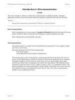
Figure 1 Ant holding a nickel micro-gear, made by LIGA technology (German for ‘lithographie, galvano-
formung, abformung’). This ant was metallized and placed in a vacuum in order to be photographed by
electron microscopy. This image was provided by the Karlsruhe group (Germany).
in the sixteenth century, the micrometr ic world has been scrutinized in detail.
The microscope permitted many scientific discoveries to be made, including
the discoveries of protazoa, Brownian motion, and chromosomes, to cite just a
few examples. However, it is far more difficult to actually act at a micrometr ic
scale, which is precisely what MEMS technology allows us to do; it is thus not
a far stretch to imagine that MEMS technology will lead to many technical and
scientific discoveries. At the time this text was written, MEMS had essentially
been created to make observations and measurements that were difficult to make
using traditional methods. Some examples include the proof of the quantum
nature of phonons [2], the measurement of fluid-phase chemical kinetics [3],
and the characterization of the slip phenomenon in gases [4]. These are all
discoveries and technical inventions that had been made possible by MEMS. In
certain cases, these advances became large industrial successes such as the usage
of MEMS in airbag activation (Fig. 2).
MEMS for airbags, which first appeared in the 1980s, consist of an integrated
system on a silicon wafer that is just a few millimeters long, and yet are able to
incorporate both electronic components and an electromechanical device cap-
able of detecting physical impact. The detection portion is only a few hundred
micrometers large and constitutes the heart of the chip. It is made of two combs,
one fixed and the other mobile; the capacitance of these combs varies under
the effect of an impact. As we will see in Chapter 1, the miniaturization of the
capacitor element allows the creation of a highly sensitive and rapid detector.
However, the industrial success of MEMS is not solely due to the improvement
INTRODUCTION 3
Figure 2 Device for the detection andcommand of airbag activation, based onMEMS technology. (Courtesy
of Analog Devices, Inc. All rights reserved)
in sensor response and sensitiv ity, but also due to the ability to integrate detec-
tion, information analysis, and signal processing all on one single chip. Just as
with integrated circuits, this chip can, in principle, be easily reproduced by the
millions. The cost, which is so critical in the field of automobile manufacturing,
becomes very advantageous as compared to traditional systems. For this reason,
all modern automobiles now use MEMS for their airbags, and tens of millions
of these devices are produced each year.
A second major industrial success came in the 1990s with the advent of MEMS
usage for inkjet printer heads (Fig. 3).
The printer head consists of a portion microfabricated from silicon that
serves as an ink reservoir, a heating element to put the fluid in motion, and a
nozzle. The fluid is pushed through the nozzle due to the formation of a bubble
near the heating element; this bubble is generated by the vaporization of the ink.
The bubble propels the fluid towards the exterior, forming a jet that destabilizes
under the action of capillary forces. Droplets created in this way have a size
similar to that of the nozzle diameter, which is generally on the order of 50 µm.
These droplets strike the paper, forming the basic spot. Smaller satellite droplets
also exist, and form a sort of procession accompanying the principal drop
(Fig. 3 right).
Today, the volume of MEMS activity is estimated to be worth between several
billion and several tens of billions of dollars
3
. In the United States, there was on
3
Due to the fluctuations of worldwide activity.
4 INTRODUCTION
2 mm
100 mm50 ms
55 ms
60 ms
65 ms
70 ms
85 ms
80 ms
85 ms
Break-off of Droplet 10V (50–85ms)
Figure 3 Figure showing a printer head of a commercial inkjet made using MEMS technology (left) and
the visualization of droplets of ink projected onto a target (right). Satellite droplets, which affect the printing
precision, are discernable [5].
average 1.6 MEMS per person in 2000, and this number is estimated at 4 MEMS
per person now. Today, there are numerous industries involved in MEMS, as
shown in Table 1, supplied by DARPA (defense)[6].
Note from the table thatthere are both new industries (ones that haveappeared
in just the last few years) as well as more traditional industr ies who use MEMS in
a significant way in their sector of activity, or who profit from developing novel
ventures by taking advantage of the potential of this young technology.
The history of the field of MEMS is an interesting one. The year 1959 is often
considered to be the beginning of the history of micro- and nanotechnologies.
In December of that year a visionary speech was given by Richard P. Feynman
during the APS (American Physical Society) meeting at Caltech. This speech was
entitled There is plenty of room at the bottom. The beginning of the speech went
as follows:
I would like to describe a field, in which little has been done, but in which an enormous
amount can be done in principle. This field is not quite the same as the others in
that it will not tell us much of fundamental physics (in the sense of, “What are the
strange particles?”) but it is more like solid-state physics in the sense that it might tell us
much of great interest about the strange phenomena that occur in complex situations.
Furthermore, a point that is most important is that it would have an enormous number
of technical applications.
INTRODUCTION 5
Table 1 Companies involved in MEMS technology in the United States (table created by DARPA)
Technological field Typical devices/
Applications
Companies Market 2003
($ Millions)
Inertial measurement accelerometers, rate sensors,
vibration detectors
TI,Sarcos, Boeing, ADI,
EG& GIC, Sensors,AMMI,
Motorola, Delco, Breed,
Systron Donner, Honeywell,
Allied Signals
700–1400
Microfluidics and
chemicaltesting/processing
gene chip, lab on chip,
chemical sensors, flow
controllers, micronozzles,
microvalves
Battelle, Samoff,
Microcosm, ISSYS, Berkeley
MicroInstruments,
Redwood, TiN Alloy,
Affymetrix, EG& GIC
Sensors, Motorola, Hewlett
Packard, tI, Xerox, Canon,
Epson Caliper, Agilent
3000–4450
Optical MEMS (MOEMS) displays, optical switches,
adaptive optics
Tanner, SDL, GE, Samoff,
Northrop-Grumman,
Westinghouse,
Interscience, SRI, CoraTek,
Lucent, Iridigm, Silicon
Light Macines, tI, optical
MEMS, Honeywell
450–950
Pressure measurement pressure sensors for
automotive, medical, and
industrial applications
Goodyear, Delco, Motorola,
Ford, EG& GIC, Sensors,
Lucas NovaSensor,
Siemens, TI
1100–2150
RF technology RF switches, filters,
capacitors, inductors,
antennas, phase shifters,
scanned apertures
Rockwell, Hughes,ADI,
Raytheon, TI, Aether
40–120
Other actuators, microrelays,
humidity sensors, data
storage, strain sensors,
microsatellite components
Boeing, Exponent, HP,
Sarcos, Xerox, Aerospace,
SRI, Hughes,AMMI, Lucas
Novasensor, Sarnoff, ADI,
EG& GIC Sensors, CP Clare,
Sielmens, ISSYS, Honeywell,
Northrop Grumman, IBM,
Kionix, TRW
1230–2470
6 INTRODUCTION
Figure 4 The first results of MEMS technology: a
beam and a spiral spring. (Courtesy of Professor
Richard S. Muller, Berkeley Sensor & Actuator
Center, University of California, Berkeley.)
First silicon beam
Feynman saw no physical reason why the 50 volumes of Encyclopedia Britannica
could not be inscribed on the head of a needle. One letter would only need to
consist of less than a dozen or so molecules. Confronted with the difficulty of
working at micrometric scales, he suggests that we should ‘train ants how to
teach mites’ how to construct miniaturized machines!
How many t imes when you are working on something frust ratingly tiny like your wife’s
wrist watch, have you said to yourself, ‘If I could only train an ant to do this!’ What I
would like to suggest is the possibility of training an ant to train a mite to do this. What
are the possibilities of small but movable machines? They may or may not be useful, but
they surely would be fun to make.
These suggestions or predictions did not remain just as part of a fantasy world,
since a few decades later, in 1995, the word ‘IBM’ was spelled out using only a
few atoms.
The first MEMS devices were created a decade after Feynman’s speech. A few
examples are listed here, without an attempt to establish a rigorous chronology.
The first microbeam was created in 1982, and the first microspring in 1988
(Fig. 4).
The first micromotor was created in 1989 (Fig. 5)
4
. It consists of an electro-
static motor, where the rotating electric field is generated by electrodes that have
been evaporated onto a platform of polysilicon. One major difficulty in its fab-
rication was that of the reduction of stiction (i.e. the combined phenomena
of adhesion and friction) of the rotor towards the substrate. Stiction is exacer-
bated by the effect of miniaturization and tends to impede the rotation of the
rotor. The solution to this problem consists of reducing the surface area of the
4
We will see in Chapter 1 that this micromotor can comprise the base element of a microturbine that
converts chemical energy to electrical energy. It is also interesting to note that microgears, fabricated
using MEMS technology, are often used today in clock making.
INTRODUCTION 7
Figure 5 The first micromotor, made at UC Berkeley by Tai and Muller in 1989. This motor has been placed
next to a human hair whose diameter is on the order of 200 µm. (Courtesy of Professor Richard S. Muller,
Berkeley Sensor & Actuator Center, University of California, Berkeley.)
2 micrometers
Figure 6 A microguitarwith nanostrings 30nm in diameter,made at Cornellby the groupof H.G.Craighead.
If this guitar could be played, it would produce a sound in the domain of MHz, which would require a
particularly sharp ear to hear.
rotor/substrate contact,which obviously makes microfabrication of this machine
more difficult.
Other examples of MEMS are presented below. A microgear, a pair of micro-
tweezers, a micro-electrovibrator, a system of inclinable mirrors that permit
communication between the ground and an airborne microengine [8], and an
astonishing microguitar possessing nanostrings that vibrate at a frequency of
MHz, Fig. 6. Not all of these objects are necessarily practical, but they allow for
exploration into a field of miniaturization where new concepts can be developed.
The invention of new microsystems has been the center of activities of laborator-
ies involved in MEMS in the 1990s. Today, a sort of maturation in the domain of
MEMS prevails, resulting in less time being spent on creating new systems and
more time being spent on investigating concrete applications.
8 INTRODUCTION
MICROVALVE FOR GAS INJECTION
SEPARATION COLUMN
(1.5 m LONG)
HEAT
CONDUCTANCE
SENSOR
Figure 7 Diagram of miniaturized gas chromatography, created by Terray in 1975 [9].
The birth of microfluidics
We now concentrate on microfluidics. In the period when silicon-based MEMS
began to take off, there were no technical obstacles in making simple microfluidic
systems [11]. Thus, the first miniaturized gas chromatography system was
created around 1975 [9,10].
This remarkable device circulated gas through microcanals etched in silicon.
The system consisted of miniaturized electromagnetic injection as well as
miniaturized thermal detection, all contained on a single chip just a few cen-
timeters wide. This achievement was an isolated one, most likely because
the separation-science community was not ready to develop silicon techno-
logies for its own needs [12]. It was only after 1991 that the advantages of
miniaturization were thrust into the spotlight, particularly for its application
to chromatography [13], and then all sorts of microfluidic systems began to
be fabricated. Appearing approximately chronologically were electrophoretic
separation systems, [14–16], electro-osmotic pumping systems [17], diffus-
ive separation systems [18], micromixers [19–22], DNA amplifiers [23–28],
cytometers [29–31], and chemical microreactors [32,33], to cite just a few
examples.
INTRODUCTION 9
Figure 8 Patients that have spinal cord lesions can
now be healed effectively thanks to the injection of
a product into the cereberospinal fluid. The efficacy
of this mode of injection is far greater than by oral
means. The company Medtronic has commercialized
these injection pumps, which are generally
implanted below the abdomen and connected to
the zone to be treated using a 500 µm diameter
catheter, which the neurosurgeon must manipulate
with great dexterity. There are also implanted
pumps for the injection of insulin into the liver for
the treatment of diabetes.
During the same period of time, microfluidics was being used to tackle fun-
damental physical questions. For example, the first experiments involving the
stretching of DNA, carried out by Chu et al. [34] in 1993, used a microfluidic
system to control the viscous stretching force applied to the molecule; for the first
time, it was possible to conduct a detailed study of the different configurations of
the stretched molecule. This experiment founded a new domain of fundamental
research: the study of the single molecule.
One of the amazing creations of microfluidics includes micropumps (Fig. 9).
Many tricky problems arise when constructing a mechanical micropump: for
example, miniaturized valves havea tendency to stick irreversibly to thesubstrate,
making it necessary to minimize the contact surface area (as was necessary for the
miniaturized motor). The micropump of the company Debiotech, schematically
represented in Fig. 9, overcame this problem elegantly. This pump is destined for
implantation in patients needing continuous injection of a product. Currently,
insulin injection pumps in the liver and Bactofen pumps in the spinal cord are
not easy to implant, particularly in children. As compared with traditional tech-
nologies, this micropump reduces its scale by an order of magnitude (Fig. 8), an
important improvement from the surgeon’s point of view as well as a significant
gain in comfort for the patient.
The first microfluidic product commercialized on a large scale was the
inkjet printer head described above (Fig. 10). Today, tens of millions of inkjet
10 INTRODUCTION
Inlet
Chamber
Counter electrode
Diaphragm
Insulating
layer
Actuation
unit
Valve
unit
Outlet
Figure 9 The future is moving towards the miniaturization of intrathecal pumps. The miniaturized pump is
just a few millimeters in size, which corresponds to an improvement of two orders of magnitude over current
intrathecal pumps.
Figure 10 The Debiotech micropump can be held on the
fingertip like a postage stamp.
printers use MEMS and billions of documents are written and read thanks to
microfluidics. By parallelizing ejection heads, droplet dispensers can also be con-
structed. In this case, the destination of these droplets is not sheets of paper, but
plates containing wells used for chemical or biological analyses.
Dropletdispensers at thistimeconstitutea substantial part of commercial activ-
ity in the field of microfluidics [7]. Currently, chips are produced by the millions
for chemistry and biology. These chips allow massive numbers of tests to be run
in parallel, allowing large amounts of data to be delivered that aid in the precise
characterization of a product. Today, this kind of technology is crucial in the
searchfor new types of medical treatments. Microfluidic systemsdo not normally
use moving parts (the micropump of the company Debiotech represents a rare
counterexample) and this constitutes a significant simplification with respect to
non-microfluidic MEMS. Consequently, it has become possible in microfluidic
systems to turn to simpler technologies, ones that are faster and less expensive
than silicon technology. We are generally referring to ‘soft’ technolog y, based on
elastomers such as PDMS (polydimethylsiloxane) or on plastic materials, which
comprise a large portion of the field today. We will return to these subjects
INTRODUCTION 11
in Chapter 6. Due to the absence of moving parts and the relative ease and
accessibility of many of these technologies, it has become possible to integrate
several elements on the same chip and to create lab-on-a-chip devices. The idea
of constructing microfactories from MEMS often came up in the 1980s, but
the difficulties involved in actually fabricating working devices using silicon
technology made this dream unattainable. For microfluidic MEMS and related
technologies that have no moving parts, the integration of different components
has since opened up a wide range of possibilities.
Microfluidics and lab-on-a-chip devices
The rapid expansion of the field of microfluidics seems to be driven in part by
the possibility of integration. The ultimate goal is to be able to detect biolo-
gical molecules, and transport, mix and characterize a raw sample, all with one
devi ce. In traditional genomic analyses, it was necessary to purify and amplify
a DNA fragment prior to analysis. This pre-treatment required complex labor
and highlights the advantage of being able to integrate all these procedures on
one chip to make it possible to directly analyse a raw sample, such as a drop of
blood or a piece of gruyere cheese. Achieving this would require miniaturizing
systems such as cytometers, separators, and bioreactors, and then connecting
them together. The domain of integra ted analysis systems has been designated
as µTAS (micro-total analysis systems) [35], or also ‘lab-on-a-chip’ systems. The
two terms are essentially synonymous. Lab-on-a-chip devices or µTAS delineate
an abundant field that includes analysers of air and water quality, diagnostics of
illnesses, and devices that replace the many functions of the nose, the tongue, etc.
The economic possibilities of this field have been estimated at tens of billions of
dollars per year.
Today, these possibilities have ceased to become just a dream. Already, in
1994, a group of researchers succeeded in fabricating a chip integrating three
different functions: the mixing of reactants, enzymatic reaction, and separation
[36]. Four years later, one single device capable of titrating aqueous solutes and
then performing the mixing, amplification, enzymatic digestion, electrophoretic
separation, and detection was published in the journal Science [37]. During the
last few years researchers have come up with all sorts of solutions to improve
and simplify the manipulation of fluids on-chip. There is still an enormous
amount of progress to be made in this domain, which is precisely one of the
tasks allocated to microfluidics.
In the meantime, lab-on-a-chip devices accomplishing a small number of
functions have already been commercialized. For example, the company Biosite
12 INTRODUCTION
Figure 11 Biosite chip. A droplet of blood is placed in an opening on
the chip. This drop is pulled towards the microfilter and the
microseparator (in the direction of the arrow) by capillarity. The results
of the analysis are given after data is analysed on a microcomputer. In
just 15 min, this diagnostic can determine whether or not a heart attack
has taken place.
Figure 12 This chip, commercialized by Agilent
Technologies, is a few centimeters long, and permits
the identification of specific genetic sequences in a
1-µl sample of roughly purified DNA. This process
takes place in just 10 min.
has commercialized systems that can take a drop of blood from a patient and
transport it by capillary force across a filter, analyse the blood in a functionalized
microcanal, and then diagnose whether or not the patient had suffered a heart
attack. The principle of the test is founded on the detection of three myocardial
proteins that are produced in abnormal quantities once a heart attack has taken
place. This system is shown in Figs. 11 and 12.
This system is not completely integrated because a computer is required to
analyse data produced by the chip, although the data-acquisition system itself
is portable. In this case, the interest of miniaturization is not just to allow for
portability, but also the rapidity of achieving results
5
. For the Biosite chip, a
5
Note that in this case, the reduction of diagnostic time is not only related to the physical phenomena
in play. It is also due to the reduction of necessary human involvement, since physico-chemical processes
are almost completely integrated.
INTRODUCTION 13
Figure 13 Agilent 2100 Bioanalyzer. The Agilent chip in the preceding figure is small in size, but it still
requires a non-miniaturized computer environment to analyse the acquired data.
diagnosis is given in 15 min, while traditional systems need several hours. Not
knowing the true nature of a patient’s condition, doctors needing to make quick
decisions sometimes end up treating non-existent cardiac problems. Further-
more, patients can be unnecessarily alarmed by a false diagnosis, believing they
have a fatal condition when in fact the problem may be much less serious.
It is worthwhile to mention other commercialized systems that are precursors
of the lab-on-a-chip systems of the future. Figure 12 represents a remarkable
miniaturized system commercialized by Agilent. Among other functions, this
system can perform genotyping, i.e. the identification of an object (a virus for
example) from characteristic sequences of genes. It is not necessary to sequence
the whole genome of a strand of DNA, but just to identify fragments. The chip
is made of a network of gel-filled microcanals, and uses a powerful separation
technique known as CEC (capillary electro-chromatography). This chip can also
idenfity RNA and proteins.
Just as for the Biosite system, integration is not complete; the device must be
used in tandem with a system for data analysis, as shown in Fig. 13
6
.
Microfluidics and chemical engineering
Another problem in microfluidics is that of miniaturization of processes for
chemical engineering. We will see in Chapter 1 that miniaturization favors heat
6
This fact can sometimes lead to a discussion of whether it is more appropriate to call these systems
‘chip-in-a-laboratory’ instead of ‘laboratory-on-a-chip.’ Clearly, there remains much progress to be
made for the complete miniaturization of a chain of analysis.
14 INTRODUCTION
Figure 14 Can a refinery be miniaturized? The problem of production volume would require massive
parallelization of lab-on-a-chip systems for chemical engineering (© J. Walker/S.P.L./Cosmos).
exchange, and allows the control of strongly endo- or exothermic reactions
that can be difficult to manage in traditional chemical engineering systems.
By improving control, selectivit y is also improved (by avoiding the formation
of unwanted chemical species). Emerging from all this came the idea of the
miniaturization of chemical factories, as shown in Fig. 14.
It is not clear whether it is possible to miniaturize the factory shown in Fig. 14.
The obvious problem that arises is whether there would be sufficient production
volume
7
: can enough volume be produced using a miniaturized system? Is it pos-
sible to displace a mountain with a small spoon? One possible idea would be to
multiply the system using massive parallelism, an approach know n as numbering
up. It is undoubtedly necessary to rethink modes of production in this domain
so that it can best profit from the advantages of miniaturization, especially to
break down units of production or install them near the users. The latter would
present many advantages, such as the reduction of transport and the reduc-
tion of chemical-contamination risks. The appeal of microsystems for chemical
engineering has been perceived at least since 1996, as cited by several references
[38, 39]. Today, microsystems are seen as an important source of innovation;
international conferences organized on this subject, such as the IMRET series,
have seen a strong vitality in research activity on the theme of miniaturization.
A recent review of these subjects is given in [40].
7
A related issue in the domains of biology and analytical chemistry is how to obtain a large amount
of data by parallelizing many miniaturized analysis units. These systems are called high-throughput
devices.