Thiết Kế Bộ Chuyển Đổi Tương Tự - Số 12 Bits Sar-Adc Nhằm Cải Thiện Hiệu Năng Màn Hình Tft.pdf
Bạn đang xem bản rút gọn của tài liệu. Xem và tải ngay bản đầy đủ của tài liệu tại đây (1.62 MB, 69 trang )
<span class="text_page_counter">Trang 1</span><div class="page_container" data-page="1">
ĐẠI HỌC QUỐC GIA HÀ NỘI TRƯỜNG ĐẠI HỌC CÔNG NGHỆ
Nguyễn Tuấn Anh
THIẾT KẾ BỘ CHUYỂN ĐỔI TƯƠNG TỰ - SỐ 12 BITS SAR-ADC NHẰM CẢI THIỆN
HIỆU NĂNG MÀN HÌNH TFT
KHĨA LUẬN TỐT NGHIỆP ĐẠI HỌC HỆ CHÍNH QUY Ngành: Cơng nghệ kỹ thuật điện tử truyền thông
HÀ NỘI – 2023
</div><span class="text_page_counter">Trang 2</span><div class="page_container" data-page="2">ĐẠI HỌC QUỐC GIA HÀ NỘI TRƯỜNG ĐẠI HỌC CÔNG NGHỆ
Nguyễn Tuấn Anh
THIẾT KẾ BỘ CHUYỂN ĐỔI TƯƠNG TỰ - SỐ 12 BITS SAR-ADC NHẰM CẢI THIỆN
HIỆU NĂNG MÀN HÌNH TFT
KHĨA LUẬN TỐT NGHIỆP ĐẠI HỌC HỆ CHÍNH QUY Ngành: Cơng nghệ kỹ thuật điện tử truyền thông
Cán bộ hướng dẫn: PGS.TS Mai Anh Tuấn
HÀ NỘI - 2023
</div><span class="text_page_counter">Trang 3</span><div class="page_container" data-page="3">VIETNAM NATIONAL UNIVERSITY, HANOI UNIVERSITY OF ENGINEERING AND TECHNOLOGY
Nguyen Tuan Anh
DESIGN 12-BIT SUCCESSIVE-APPROXIMATION DIGITAL-TO-ANALOG CONVERTER (SAR-ADC) TOWARD AN IMPROVEMENT OF TFT DISPLAY
Major: Faculty of Electronics and Telecommunications
Supervisor: Assoc. Prof. Mai Anh Tuan
HA NOI - 2023
</div><span class="text_page_counter">Trang 4</span><div class="page_container" data-page="4">TÓM TẮT NỘI DUNG
Tóm tắt: Ngày nay, trong thế giới của các dụng cụ đo lường khoa học, hầu như tất cả các kết quả đo lường đều được số hoá, tức là được chuyển đổi sang miền kĩ thuật số. Đầu ra tương tự của các cảm biến như cặp nhiệt điện, máy đo biến dạng, máy đo gia tốc, cảm biến lực và chuyển vị, v.v., được số hoá cho mục đích ghi, hiển thị và phân tích. Máy tính kĩ thuật số có thể tương tác với các tín hiệu phổ biến này nhờ chuyển đổi tương tự sang kĩ thuật số. Bộ chuyển đổi tương tự sang số là bộ chuyển đổi tín hiệu tương tự sang tín hiệu số, gọi tắt là ADC ( Analog to Digital Converter). Có rất nhiều loại ADC trên thị trường, trong đó có SAR-ADC, loại này có nhiều ưu điểm hơn các loại ADC khác, nó có độ chính xác cao và tiêu thụ điện năng thấp. Do có độ chính xác cao nên SAR-ADC thường được dùng để cải thiện hiệu năng cho các loại màn hình cảm ứng điện trở có trên thị trường. Loại màn hình cảm ứng điện trở là loại màn hình cảm ứng đơn điểm, nhược điểm của loại màn hình này là có độ trễ khá lớn và độ chính xác khơng cao. SAR-ADC hồn tồn có thể khắc phục những nhược điểm đó trên màn hình cảm ứnng điện trở, cụ thể là màn hình TFT.
Từ khóa: SAR-ADC.
i
</div><span class="text_page_counter">Trang 5</span><div class="page_container" data-page="5">Abstract: Today, in the world of scientific measuring instruments, almost all measurement results are digitized, i.e. converted to the digital domain. Analog outputs of sensors such as thermocouples, strain gauges, accelerometers, force and displacement sensors, etc., are digitized for recording, display and analysis purposes. Digital computers can interact with these common signals by converting analog to digital. An analog to digital converter is an analog to digital converter, referred to as ADC (Analog to Digital Converter). There are many types of ADCs on the market, including SAR-ADC, which has many advantages over other ADCs, it has high accuracy and low power consumption. Due to its high accuracy, SAR-ADC is often used to improve the performance of resistive touch screens on the market. Resistive touch screen type is a single-point touch screen, the disadvantage of this type of screen is that it has a large delay and is not accurate. SAR-ADC can completely overcome those disadvantages on resistive touch screens, specifically TFT display
Keywords: SAR-ADC.
ii
</div><span class="text_page_counter">Trang 6</span><div class="page_container" data-page="6">First of all, I would like to express my sincere and deep gratitude to Assoc. Prof. Mai Anh Tuan for his dedicated guidance and advice, providing valuable experiences for me during the time of researching and carrying out my thesis.
I also want to express my sincere thanks to the teachers in the University of Engineering and Technology for creating opportunities for me to study and develop myself during my four years at the school, helping me acquire the basic skills to be able to complete my thesis. Furthermore, having these skills prepared me to take on the world with confidence.
Although I have tried my best, my graduation thesis cannot avoid some shortcomings. I respectfully request the teachers and friends to provide suggestions to improve my thesis.
Finally, I wish the teachers and everyone good health and success in their life and teaching careers, and to prepare the next generation of knowledgeable citizens for the
</div><span class="text_page_counter">Trang 7</span><div class="page_container" data-page="7">LỜI CAM ĐOAN
Tôi xin cam đoan đề tài “Thiết kế bộ chuyển đổi tương tự - số 12 bit SAR-ADC nhằm cải thiện hiệu năng của màn hình TFT ” là khóa luận tốt nghiệp do chính bản thân mình thực hiện trong suốt thời gian vừa qua dưới sự hướng dẫn của PGS.TS. Mai Anh Tuấn. Những số liệu và kết quả nghiên cứu là hoàn toàn trung thực và không sao chép của người khác mà không chỉ rõ về mặt tài liệu tham khảo. Nếu khơng đúng sự thật, tơi xin chịu hồn tồn trách nhiệm.
Hà Nội, ngày…tháng…năm 2023 Sinh viên
Nguyễn Tuấn Anh
iv
</div><span class="text_page_counter">Trang 8</span><div class="page_container" data-page="8">1.4. The impact of ADC on the performance of TFT Display...18
1.5. Compare SAR ADC and conventional ADC...19
1.6. Objective... 19
v
</div><span class="text_page_counter">Trang 9</span><div class="page_container" data-page="9">CHAPTER 2. LITERATURE REVIEW...21
CHAPTER 3. DESIGN...24
3.1. SAR ADC architecture and operation...24
3.2. Sample and Hold circuit...25
3.2.1. Cmos Technology...27
3.2.2. Bootstrapped sample and hold circuit...29
3.3. Digital Analog Converter circuit...30
3.3.1. Split capacitor Digital to Analog Converter...35
3.3.2. Perform...36
3.4. Comparator circuit...36
3.4.1. Comparative Criteria...40
3.5. Successive-Approximation-Register control logic block...41
3.5.1. D flip-flops with Set/Reset...42
3.5.2. Perform...43
CHAPTER 4. RESULTS AND CONCLUSIONS...46
4.1. RESULTS... 46
4.1.1. Sample and Hold...46
4.1.2. Digital to Analog converter...46
</div><span class="text_page_counter">Trang 10</span><div class="page_container" data-page="10">vii
</div><span class="text_page_counter">Trang 11</span><div class="page_container" data-page="11">IMAGE CATALOG
Figure 1: Vacuum Tubes... 6
Figure 2: Typical example of Nyquist frequency and rate...7
Figure 3: Early telegraph machine...8
Figure 4: Electronic magazine, Jun 1954-The silicon transister...8
Figure 5: Block diagram of the Delta-sigma ADCs...11
Figure 6: Showing the comparator, timer, and controller...12
Figure 7: Pipelined ADC illustration...13
Figure 8: Block diagram of the SAR-ADC...15
Figure 9: TFT LCD Display Layer...16
Figure 10: Application of TFT...17
Figure 11: SAR-ADC blocks...22
Figure 12: A 3-bit SAR ADC example...23
Figure 13: Sample and Hold simulation...24
Figure 14:Basic Track & Hold (T&H) circuit...25
Figure 15: NMOS pass gate and a PMOS pass gate...27
Figure 16:Working principle of Bootstrapped...28
Figure 17: Operation diagram of DAC block...30
Figure 18: DAC block simulation...30
Figure 19: DAC classification...32
Figure 20: Structure of Split Capacitor DAC...33
Figure 21: Switches of capacitors...34
Figure 22: Comparator block simulation...36
Figure 23: Positive feedback decision circuit...37
Figure 24: Self bias buffer...37
Figure 25: Pre-amplifier...37
Figure 26: SAR block simulation...39
viii
</div><span class="text_page_counter">Trang 12</span><div class="page_container" data-page="12">Figure 27: Successive-Approximation-Register control logic block...40
Figure 28: D Flip-flop circuit which uses NAND gate 3-to-1 to build up this structure ... 41
Figure 29: Simulation the Sample and Hold...44
Figure 30: Simulation DAC with Vin = 600mV, Vref = 1V...45
Figure 31: Simulation Comparator with Vin = 600mV, Vref = 1V...45
Figure 32: Simulation SAR control logic with Vin = 600mV, Vref = 1V...46
Figure 33: Simulation SAR control logic with Vin = 900mV, Vref = 1V...47
Figure 34: Simulation SAR control logic with Vin = 700mV, Vref = 1V...47
Figure 35: Simulation SAR control logic with Vin = 600mV, Vref = 1V...48
ix
</div><span class="text_page_counter">Trang 13</span><div class="page_container" data-page="13">LIST OF TABLES
Table 1: First Row Register Outputs...42 Table 2: Second Row Outputs...42
x
</div><span class="text_page_counter">Trang 14</span><div class="page_container" data-page="14">The meaning of the topic
The SAR ADC digital-to-analog converter aims to optimize the conversion from analog signal to digital signal in TFT display. This converter will help improve image quality, increase processing speed and reduce errors in the conversion process.
The project "Designing a SAR ADC digital-to-analog converter to improve TFT display performance" tries to solve performance problems in converting analog to digital signals on TFT screens. . A SAR ADC digital-to-analog converter is used to improve the signal quality and ensure the accuracy of the output signal.
In addition to improving performance, SAR ADC digital-to-analog converters also help save costs and reduce complexity in the manufacturing process.
Through the implementation of this topic, it is desired to solve the problems of signal conversion on TFT screens and provide users with a better experience in using TFT screens.
Content of the topic
Theses “Design 12-Bit Successive-Approximation Digital-To-Analog Converter (SAR-ADC) Toward An Improvement of TFT Display Performance” will describe, design and test a SAR ADC digital-to-analog converter that can improve the performance of the TFT. Specifically, the accuracy, mode and power consumption of the TFT
In order to enhance the performance of TFT, I shall create an analog to digital converter in my thesis. Therefore, ideal power and excellent resolution are needed. The Analog-to-Digital Converters of Consecutive Approximation are the most appropriate ADC to meet the criteria, according to section 1.2 analysis of the benefits and drawbacks of ADCs.
My goal is not only to develop a low power 12-bit sequential approximation Analog to Digital Converter (SAR-ADC) based on CMOS technology (90nm protocol) with internal voltage reference + 2.5V, 10ms transition time, basic features of SAR ADC, including Differential Nonlinearity – DNL (1 LSB) and Integral Nonlinearity – INL (1 LBS), were measured, but also to cultivate more knowledge about integrated circuit design such as design diagram, digital design, simulation, IC layout, basic knowledge
1
</div><span class="text_page_counter">Trang 50</span><div class="page_container" data-page="50">A standard comparator circuit has two inputs: an analog input signal and a DAC output signal. Based on the comparison of these two input signals, the comparator circuit provides a digital output signal. If the DAC output signal exceeds the input signal, the comparator produces a digital output of '0,' indicating that the DAC output voltage should be reduced. If the DAC output signal is less than the input signal, the comparator outputs a digital value of '1,' indicating that the DAC output voltage should be increased.
The precision and speed of the comparator circuit are essential variables in determining the overall performance of the SAR ADC. The offset voltage, hysteresis, and noise of the comparator circuit determine its accuracy. When the input signals are equal, the offset voltage is the voltage difference between the comparator's input terminals. The difference in voltage levels at which the comparator flips from high to low and low to high is referred to as hysteresis. The random variation in the comparator's output voltage caused by internal and external sources is referred to as noise.
Several strategies for optimizing the performance of the comparator circuit have been devised. Offset voltage, for example, can be reduced by designing the comparator circuit using symmetrical input transistors. By incorporating feedback into the comparator circuit, hysteresis can be reduced. Noise can be reduced by using low-noise amplifiers and filtering techniques in the comparator circuit design. The comparator circuit in modern SAR ADCs is frequently developed utilizing advanced techniques like as dynamic comparators, latch comparators, and regenerative comparators. These modern comparator circuits are built for high accuracy, fast speed, and low power consumption.
To summarize, the comparator circuit is an important component of the SAR ADC and has a substantial impact on the ADC's overall performance. Researchers and engineers will continue to explore new and inventive techniques to developing comparator circuits that improve the performance of SAR ADCs in diverse applications as technology advances.Comparator circuits are built with high precision, fast speed, and low power consumption in mind.
37
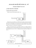
</div><span class="text_page_counter">Trang 51</span><div class="page_container" data-page="51">Figure 22: Comparator block simulation
A SAR ADC's comparator circuit can be implemented using a variety of amplifier circuits, including open-loop amplifiers, folded-cascode amplifiers, and two-stage amplifiers. The open-loop amplifier is the most basic, but its performance is limited due to its low gain and bandwidth. Higher gain and bandwidth are provided by the folded-cascode amplifier and the two-stage amplifier, but they are more complex and consume more power.[30]
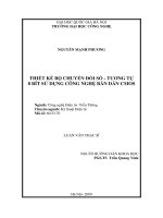
Figure 23: Positive feedback decision circuit
38
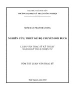
</div><span class="text_page_counter">Trang 52</span><div class="page_container" data-page="52">Figure 24: Self bias buffer
Figure 25: Pre-amplifier
To achieve high resolution and accuracy in SAR ADCs, the comparator circuit should have a high gain, high speed, and a low offset voltage. Furthermore, to reduce power consumption, the comparator circuit should be designed to operate at low supply voltages[31]
39
</div><span class="text_page_counter">Trang 53</span><div class="page_container" data-page="53">The main calculation formula used in the block as:
In there:
- V<small>out</small> is the output of the comparator block. - V<small>REF</small> is the reference voltage of the DAC block. - D is the bit being compared during sampling. - V<small>in</small> is the input voltage from the DAC block. - V<small>cm</small> is the common voltage of the comparator block.
The above formula allows to compare the input voltage from the DAC block with a threshold set by adjusting D. If the input voltage is greater than the threshold, the output of the comparator block will be "1", otherwise it will be "0". Therefore, this formula along with other parameters of the SAR ADC affects its accuracy and resolution.
3.4.1. Comparative Criteria
The comparator is an important component in SAR ADC because it compares the input voltage to a reference voltage and generates a digital output based on the result of the comparison. The characteristics of the comparator can have a significant impact on the SAR ADCs overall performance. Some of the important comparator characteristics in SAR ADC are:
- Input offset voltage: The minimum voltage difference required between the input and the reference voltage to change the comparator's output state. A low input offset voltage reduces the output error of the comparator [32]
- Input offset drift: Input offset drift is the change in the input offset voltage over time and temperature. A low input offset drift ensures that the comparator's output remains stable over a wide range of temperatures and operating conditions[33]
- Input common-mode range: Input common-mode range is the range of input voltages that the comparator can handle without saturating or producing an incorrect output. A wide input common-mode range ensures that the comparator can handle a broad range of input signals[34]
- Propagation delay: Propagation delay is the time it takes for the comparator to change its output state after the input voltage changes. A low propagation delay
40
</div><span class="text_page_counter">Trang 54</span><div class="page_container" data-page="54">is essential for high-speed SAR ADCs as it directly impacts the overall conversion rate[35]
- Hysteresis: Hysteresis is the difference between the input voltages required to change the comparator's output state from high to low and low to high. A small hysteresis improves the comparator's stability and reduces noise in the output.36]
- Power consumption: Comparator power consumption is an important consideration in SAR ADC design as it can affect the overall power consumption of the system. Low power consumption comparators can significantly improve the energy efficiency of the SAR ADC.
In summary, the comparator's characteristics in SAR ADCs are essential to ensure high accuracy, stability, and speed in converting the input analog signal into digital form. Designers need to carefully consider these characteristics to choose the right comparator for their SAR ADC design.
3.5. Successive-Approximation-Register control logic block
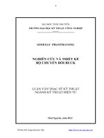
Figure 26: SAR block simulation
Successive-Approximation-Register control logic block (control logic) is required to execute the binary search algorithm in order to determine the quantization level that corresponds to the final analog input of SAR ADC.
41
</div>