International journal of engineering science invention
Bạn đang xem bản rút gọn của tài liệu. Xem và tải ngay bản đầy đủ của tài liệu tại đây (735.96 KB, 10 trang )
<span class="text_page_counter">Trang 1</span><div class="page_container" data-page="1">
<i>ISSN (Online): 2319 – 6734, ISSN (Print): 2319 – 6726 www.ijesi.org ||Volume 4 Issue 6|| June 2015 || PP.52-61 </i>
www.ijesi.org 52 | Page
<b>Theoretical Analysis of Stress and Design of Piston Head using CATIA & ANSYS </b>
Dilip Kumar Sonar,
<sup>2,</sup>Madhura Chattopadhyay
<i><small>1, </small> Asst.Prof. of Mechanical Engg. </i>
<i><small>1, 2, </small>Dept of College of Engineering & Management Kolaghat. KTPP Township </i>
<i><b>ABSTRACT: </b></i>
<i>Engine pistons are one of the most complex components among all automotive or other industry field components. The engine can be called the heart of a car and the piston may be considered the most important part of an engine. There are lots of research works proposing, for engine pistons, new geometries, materials and manufacturing techniques, and this evolution has undergone with a continuous improvement over the last decades and required thorough examination of the smallest details. Notwithstanding all these studies, there are a huge number of damaged pistons. Damage mechanisms have different origins and are mainly wear, temperature, and fatigue related. Among the fatigue damages, thermal fatigue and mechanical fatigue, either at room or at high temperature, play a prominent role. In this present work a piston is designed using CATIA V5R20 software. Complete design is imported to ANSYS 14.5 software then analysis is performed. Aluminium alloy have been selected for structural and thermal analysis of piston. An analysis of thermal stress and damages due to application of pressure is presented and analyzed in this work. Results are shown and a comparison is made to find the most suited design. </i><i><b>KEY WORDS: </b></i>
<i>Stress, pressure, temperature </i>Engine pistons are one of the most complex components among all automotive and other industry field components. The engine can be called the heart of a vehicle and the piston may be considered the most important part of an engine. There are lots of research works proposing, for engine pistons, new geometries, materials and manufacturing techniques, and this evolution has undergone with a continuous improvement over the last decades and required thorough examination of the smallest details. Notwithstanding all these studies,
<i><b>there are a huge number of damaged pistons. Damage mechanisms have different origins and are mainly wear, </b></i>
<i><b>temperature, and fatigue related. But more than wear and fatigue, damage of the piston is mainly due to stress </b></i>
<i><b>development, namely- Thermal stress, Mechanical stress. . This paper describes the stress distribution on </b></i>
piston of internal combustion engine by using FEA. The FEA is performed by CAD and CAE software. The main objectives are to investigate and analyze the thermal stress and mechanical stress distribution of piston at the real engine condition during combustion process. The paper describes the FEA technique to predict the higher stress and critical region on the component. With using CATIAV5 software the structural model of a piston will be developed. Using ANSYS V14.5 software, simulation and stress analysis is performed. A piston is a component of reciprocating IC-engines. It is the moving component that is contained by a cylinder and is made gas-tight by piston rings. In an engine, its purpose is to transfer force from expanding gas in the cylinder to the crankshaft via a piston rod. In engine, transfer of heat takes place due to difference in temperature and from higher temperature to lower temperature. Thus, there is heat transfer to the gases during intakes stroke and the first part of the compression stroke, but the during combustion and expansion processes the heat transfer take place from the gases to the walls. So the piston crown, piston ring and the piston skirt should have enough stiffness which can endure the pressure and the friction between contacting surfaces. In addition, as an important part in engine, the working condition of piston is directly.
</div><span class="text_page_counter">Trang 2</span><div class="page_container" data-page="2">
<b>II. LITERATURE REVIEW </b>
An optimized piston which is lighter and stronger is coated with zirconium for bio-fuel. In this paper[1], the coated piston undergone a Von misses test by using ANSYS for load applied on the top. Analysis of the stress distribution was done on various parts of the coated piston for finding the stresses due to the gas pressure and thermal variations. Vonmisses stress is increased by 16% and deflection is increased after optimization. But all the parameters are well with in design consideration. Design, Analysis and optimization of piston [2] which is stronger, lighter with minimum cost and with less time. Since the design and weight of the piston influence the engine performance. Analysis of the stress distribution in the various parts of the piston to know the stresses due to the gas pressure and thermal variations using with Ansys. With the definite-element analysis software, a three-dimensional definite-element analysis [3] has been carried out to the gasoline engine piston. Considering the thermal boundary condition, the stress and the deformation distribution conditions of the piston under the coupling effect of the thermal load and explosion pressure have been calculated, thus providing reference for design improvement. Results show that, the main cause of the piston safety, the piston deformation and the great stress is the temperature, so itis feasible to further decrease the piston temperature with structure optimization. This paper [4] involves simulation of a 2-stroke 6S35ME marine diesel engine piston to determine its temperature field, thermal, mechanical and coupled thermal-mechanical stress. The distribution and magnitudes of the afore-mentioned strength parameters are useful in design, failure analysis and optimization of the engine piston. The piston model was developed in solid-works and imported into ANSYS for preprocessing, loading and post processing. Material model chosen was 10-node tetrahedral thermal solid 87. The simulation parameters used in this paper were piston material, combustion pressure, inertial effects and temperature. This work [5] describes the stress distribution of the piston by using finite element method (FEM). FEM is performed by using computer aided engineering (CAE) software. The main objective of this project is to investigate and analyze the stress distribution of piston at the actual engine condition during combustion process.. The report describes the mesh optimization by using FEM technique to predict the higher stress and critical region on the component. The impact of crown thickness, thickness ofbarrel and piston top land height on stress distribution and total deformation is monitored during the study[6] of actual four stroke engine piston. The entire optimization is carried out based on statistical analysisFEA analysis is carried out using ANSYS for optimum geometry.This paper describes the stress distribution and thermal stresses of three different aluminum alloys piston by using finite element method (FEM). The parameters used for the simulation are operating gas pressure, temperature and material properties of piston. The specifications used for the study of these pistons belong to four stroke single cylinder engine of Bajaj Kawasaki motorcycle.
The piston are made of different materials such as Carbon steel,Cast Iron , Aluminum alloys etc. For our work, material selected as Aluminum Alloy .Pistons are commonly made of aluminum alloy .Generally in this material aluminum is the main component. In addition to main component aluminum it consists of copper 4-5%, ferrous -1.3%, silicon- 16 to18%, magnesium- 0.45-65%, zinc- 1.5% and nickel- 0.1% aluminum alloy is used for excellent and lightweight thermal conductivity. Thermal conductivity is the ability of a material to conduct and transfer heat. Aluminum expands when heated and proper clearance must be provided to maintain free piston movement in the cylinder bore. Piston material was assumed to be aluminum alloy which is homogenous, isotropic and linear elastic with a Poisson’s ratio of 0.33.
The Physical and material properties of Aluminum Alloy are given below: [4] Density – 2770 (Kg/m<sup>3</sup>)
Poisson Ratio – 0.33
Young Modulus – 7.1x10<sup>10</sup> (Pa) Tensile Ultimate Strength – 3.1x10<sup>8</sup>(Pa) Tensile Yield Strength – 2.8x10<sup>8</sup>(Pa) Compressive Yield strength – 2.8 x10<sup>8</sup>(Pa)
<i><b>Calculations : Analytical Design </b></i>
<i><b>mp = mass of the piston (Kg) V = volume of the piston (mm</b></i><sup>3</sup>)
<i><b> th = thickness of piston head (mm) </b></i>
<i>D = cylinder bore (mm) </i>
<i><b> pmax = maximum gas pressure or explosion pressure (MPa) </b></i>
<i><b> σt = allowable tensile strength (MPa) </b></i>
</div><span class="text_page_counter">Trang 3</span><div class="page_container" data-page="3">www.ijesi.org 54 | Page
<i><b> k = thermal conductivity =174.15(W/m C) </b></i>
<i><b> Tc = temperature at the centre of the piston head (</b></i><sup>0</sup>C)
<i><b>Te = temperature at the edge of the piston head (</b></i><sup>0</sup>C)
<i><b>HCV = Higher Calorific Value of fuel (KJ/Kg) = 47000 KJ/Kg (petrol) </b></i>
<i><b> BP = brake power of the engine per cylinder (KW) =4KW. Value obtained experimentally considering the </b></i>
following conditions. N=1500rpm, Compression Ratio (r<sub>c</sub>) =16.5, fully loaded condition.
<i><b>m = mass of fuel used per brake power per second (Kg/KW s) =0.25/3600 (Kg/KW s).Value obtained </b></i>
experimentally considering the following conditions:B.P=4KW, CV=47000Kj/kg (petrol), N=1500, fully loaded condition.
<i><b> C = ratio of heat absorbed by the piston to the total heat developed in the cylinder = 5% or 0.05 b = radial thickness of ring (mm) </b></i>
<i><b> Pw = allowable radial pressure on cylinder wall (N/mm</b></i><sup>2</sup>) = 0.042 MPa
<i><b> h2 = axial thickness of piston ring (mm) </b></i>
<i><b> t1 = thickness of piston barrel at the top end (mm) t2 = thickness of piston barrel at the open end (mm) do = outer diameter of piston pin (mm) </b></i>
Engine Specifications: Engine make: Kirloskar Bore Diameter: 80mm Stroke Length: 110mm.
<i><b>Calculation of Dimensions Of Piston For Analysis:[8] </b></i>
<b>Thickness of Piston Head (tH) : The piston thickness of piston head calculated using the following Grashoff’s </b>
t<sub>H</sub>= 8.9mm.
<b>Heat Flow through the Piston Head (H) </b>
The heat flow through the piston head is calculated using the formula H = 12.56*t<sub>H</sub> * k * (Tc-Te) KJ/sec
t<sub>H</sub> = H/(12.56 x k (Tc – Te)) = Hx1000/12.56 x 174.15 x 75 =3.98mm.
Comparing both the dimensions, for design purpose we will be considering the maximum thickness, hence required thickness of piston head is 8.9mm.
</div><span class="text_page_counter">Trang 4</span><div class="page_container" data-page="4"><b>Radial Thickness of Ring (t1): </b>
t<sub>1</sub> = D√3p<sub>w</sub>/σ<sub>t</sub>Where,
D = cylinder bore in mm=80mm.
Pw= pressure of fuel on cylinder wall in N/mm². Its value is limited from 0.025N/mm² to 0.042N/mm². Here P<sub>w</sub>value is taken as 0.042N/mm² while σ<sub>t</sub>= 124.4Mpa for aluminum alloy.
(t1): 3mm.
<b>Axial Thickness of Ring (t2) </b>
The thickness of the rings may be taken as t<sub>2</sub> = 0.7t<sub>1</sub> to t<sub>1</sub>
<b>Width of the top land (b1) </b>
The width of the top land varies from b<sub>1</sub> = t<sub>H</sub> to 1.2 t<sub>H</sub>
=1.2 t<small>H</small> = 1.2 x8.9 =10.68mm.
<b>Width of other lands (b2): </b>
Width of other ring lands varies from b<sub>2</sub> = 0.75t<sub>2</sub> to t<sub>2</sub>
=0.75 t<small>2</small>= 0.75x2.1=1.575mm.
<b>Maximum Thickness of Barrel at the top end (t3): </b>
Radial depth of the piston ring grooves (b) is about 0.4 mm more than radial thickness of the piston rings(t<sub>1</sub>),therefore
b = 0.4 +t<sub>1 </sub>=0.4+3 =3.4 mm t<sub>3</sub> = 0.03*D + b + 4.5 mm t<sub>3</sub>=0.03*80+3.4+4.9=10.7mm.
<b>Thickness of piston barrel at the open end (t</b><sub>4</sub>): t<sub>4</sub>= 0.25 t<sub>1</sub> to 0.35 t<sub>1</sub>)
t<sub>4</sub>=0.25*10.7=2.675mm
<b>Piston pin diameter (d<sub>o</sub>): </b>
d<sub>o</sub>=0.03D=24mm.
<b>Theoretical Stress Calculation: </b>
<i>The piston crown is designed for bending by maximum gas forces Pzmax as uniformly loaded round plate freely </i>
supported by a cylinder. The stress acting in MPa on piston crown: σb=Mb/Wb=Pzmax(ri/δ)2
Where ,
<i>M<sub>b</sub> = (1/3) Pzmax r<sub>i</sub><sup>3</sup> is the bending moment, MN m; </i>
<i>W<sub>b</sub> = (1/3) riδ<sup>2</sup> is the moment of resistance to bending of a flat crown, m3; </i>
</div><span class="text_page_counter">Trang 5</span><div class="page_container" data-page="5">www.ijesi.org 56 | Page
This value varies from 2Mpa-5Mpa in case of aluminium alloy.<i> ri = [D / 2 - (s + t1 + dt)] is the crown inner radius, m.; </i>
Where, Thickness of the sealing part s = 0.05D= 0.05X80=4mm. Radial clearance between piston ring and channel :dt= 0.0008m
<i>Radial thickness of ring (t<sub>1</sub></i>) =3mm.
<i>Therefore, ri=[0.08/2-(0.004+0.003+0.0008)]=0.0322m </i>
Thickness of piston crown δ=(0.08 to 0.1)XD= 0.085X80=7mm. σb= 5X[(0.0322/0.007)^2] Mpa= 105.8Mpa.
<i><b>Hence required theoretical stress obtained from calculation is 105.8Mpa. </b></i>
For the design to be failsafe, the obtained value of theoretical stress must be less than the allowable stress. Allowable stress calculated previously was 124.4Mpa, which is greater than the obtained stress
<i><b>(105.8Mpa). Hence the design is safe. i,e Obtained stress (105.8Mpa) < Allowable stress (124.4Mpa) </b></i>
<b> </b>
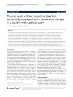
Designing the model using CATIA:
FIG:1 Considering the above calculations, the model has been designed in CATIA
</div><span class="text_page_counter">Trang 6</span><div class="page_container" data-page="6"><b>Analysis Of the Model: </b>
Here Stress analysis of the piston model has been performed to obtain the value and parameters at which the piston would be damaged. Damages may have different origins: mechanical stresses; thermal stresses; wear mechanisms; temperature degradation, oxidation mechanisms; etc. For this analysis parameters like Pressure, Temperature, Thermal Stress. have been used and to discuss the effects of these parameters on the model are as follows:
<b>PRESSURE: </b>
When air-fuel mixture is ignited, pressure from the combustion gases is applied to the piston head, forcing the piston towards the crankshaft. Due to the pressure at the piston head, there are mainly two critical areas: piston pin holes and localized areas at the piston head. Subsequently will be presented different engine pistons where the cracks initiated on those areas. The pressurized gases travel through the gap between the cylinder wall and the piston. The upward motion of the piston is against the pressure of the gases. The causes a tremendous effect on the piston head leading to its damage and deformation of the piston head.
<b>THERMAL STRESS: </b>
a) Thermal stresses are difficult to simulate because there are, in a piston, two kinds of thermal stresses. Thermal stresses due to the vertical distribution of the temperature along the piston high temperatures at the top and lower temperatures at the bottom. There is a homogeneous and regular gradient of temperature on the radial direction along the head of the component. It is observed that the bowl rim area is the area where temperatures are higher. Thermal deformations under the operating bowl rim temperature are constrained by the surrounding material. This causes large compressive stresses on the total bowl rim circumference that often exceed the yield strength of the material. After creep relaxation of the high compressive stresses and when the piston gets cold creep effect gives rise to tensile residual stresses on the bowl rim. This cyclic stresses origins cracks distributed all around the rim area.
b) Thermal stresses due to the different temperatures at the head of the piston due to the flow of the hot gases or to fuel impingement (related to high-pressure injection). This distribution causes localized warmer areas. The mechanism under which the thermal cracks form is the same as mentioned in (a) with the exception that in this case these warmer areas will have higher compressive stresses – followed by creep – followed by higher tensile stresses when the piston gets cold. Thus, in this case is most probable that localized areas at the bowl rim will concentrate the thermal fatigue cracks.
<b>Analyzing the model in ANSYS: </b>
After designing the model in CATIA, the CAT FILE has been converted to IGES format. This format enables the design to be compatible in the ANSYS software. After importing the design in ANSYS, the process of analysis begins. The different steps performed for the proper analysis of the model are as follows:
<b>Applying material to the model: </b>
Since here we are considering that the material with which he model is made up of is Al Alloy, hence we add this particular material to the designed model constructed in CATIA. By doing this the model will be having similar characteristics of the Al Alloy, such as Density, Poisson Ratio, Young Modulus, Tensile Ultimate Strength, Tensile Yield Strength, Compressive Yield strength.
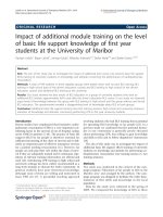
<b>Meshing the model: </b>
Mathematically, the structure to be analyzed is subdivided into a mesh of finite sized elements of simple shape. Within each element, the variation of displacement is assumed to be determined by simple polynomial shape functions and nodal displacements. Equations for the strains and stresses are developed in terms of the unknown nodal displacements. From this, the equations of equilibrium are assembled in a matrix form which can be easily programmed.
</div><span class="text_page_counter">Trang 7</span><div class="page_container" data-page="7">www.ijesi.org 58 | Page
FIG:2 Meshing the piston model using ANSYS<b>Analysis Of the Model using ANSYS: </b>
<i><b>PRESSURE: </b></i>
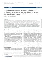
In this project, KIRLOSKAR ENGINE is considered and design is made according to the specification of its commercial piston. From calculation, we obtained that the allowable stress or failsafe stress of the piston is 124.4MPa and the obtained stress is 105.8MPa. While analyzing, using STATIC STRUCTURAL ANALYSIS, first analysis is performed considering pressure only. Here the pressure under consideration is 5MPa. Pressure is applied on the piston head and the pin hole is considered as the fixed support. After the completion of the analysis, stress obtained is exactly same as the theoretical result, i.e. stress obtained only considering stress is 105.8MPa.
<b>Integration Point Results </b>
Display Option Averaged
<b>Results </b>
Minimum 0. MPa 0. mm Maximum 105.88 MPa 0.5263 mm
</div><span class="text_page_counter">Trang 8</span><div class="page_container" data-page="8">FIG: REPORT generated by ANSYS after analysis the piston model considering PRESSUE only.
<b>FIG 5 : Concentration of PRESSURE is maximum at the HEAD and pin hole of the piston </b>
<b> FIG 6: Critical areas of stress accumulation due to application of pressure </b>
<b>FIG 7 : Petrol engine piston with a crack from one side of the pin hole to the head. </b>
<i><b>THERMAL STRESS: </b></i>
In reality, the piston is only subjected to pressure, TEMPERAURE also plays a vital role. Due to high temperature and overheating of the piston severe damage can take place which to the piston. Hence considering both the effects of PRESSURE and TEMPERATURE, analysis is performed. After performing the THERMAL STRESS analysis, it was seen that the stress generated is more than the stress obtained while performing analysis only considering pressure. Here we considered the temperature difference (T)at the centre of the piston head (<sup>0</sup>C)and at the edge of the piston head (<sup>0</sup>C), i.e.75°C. Due to the effective combination of temperature and pressure the resultant stress obtained is 115.51MPa. From theoretical calculation, we obtained the value of allowable stress as 124.4MPa. This value is much closer to the allowable stress than the value obtained when only pressure was considered. This stress is more prone to damage due to failure since 115.51MPa is closer to the value of allowable tress which is 124.4MPa.
</div><span class="text_page_counter">Trang 9</span><div class="page_container" data-page="9">www.ijesi.org 60 | Page
<b>FIG 8: VON MISES STRESS ANALYSIS of the piston FIG 9: TOTAL DEFORMATION ANALYSIS of </b>
the piston
<b> Results(STRESS) </b>
Minimum 0. MPa 0. mm Maximum 115.51 MPa 0.57414 mm Minimum Occurs On Solid
Maximum Occurs On Solid
FIG10: REPORT generated by ANSYS after analysis the piston considering TEMPERATURE and PRESSURE
<b>Definition </b>
Type Frictionless Support Pressure
FIG11: PRESSURE applied to the piston during analysis.
<b>Results </b>
Minimum 0. MPa 0. mm Maximum 115.51 MPa 0.57414 mm Minimum Occurs On Solid
Maximum Occurs On Solid
FIG12: REPORT generated by ANSYS showing DEFORMATION of piston during THERMAL STRESS ANALYSIS
<b>FIG 13: REPORT generated by ANSYS showing Temperature given as input during THERMAL STRESS </b>
ANALYSIS
Object Name <i>Temperature Temperature 2 Convection </i>
<b>Scope </b>
Scoping Method Geometry Selection
<b>Definition </b>
Magnitude <sup>473. K </sup>(ramped)
</div><span class="text_page_counter">Trang 10</span><div class="page_container" data-page="10"><b>FIG 14 : Examples of thermal stresses at the top of a piston DISCUSSIONS: </b>
From this project the piston gets affected in different mechanisms.The allowable stress has been drived which the piston can undergo deforme . The factors has been studied which affects the piston the most. The stress distribution on the piston mainly depends on the deformation of piston. Therefore, in order to reduce the stress concentration, the piston crown should have enough stiffness to reduce the deformation. The deformation and the stress of the piston are mainly determined by the temperature, so it is necessary to decrease the piston temperature through structure improvement, e.g. by using the combined piston with small heat conduction coefficient and large heat conduction coefficient of the skirt and inner cylinder. Learning all to derive out ways how to avoid these problems so that the lifespan and effectiveness of the piston increases. In this project the design specifications provided by KIRLOSKAR ENGINE is used. If the piston manufacturing companies follow these prototypes to design a piston, there is an assurance that the life span and effectiveness of the piston will be way better than the ordinary designed pistons.
<b>CONCLUSIONS: </b>
The first main conclusion that could be drawn from this work is that although thermal stress is not the responsible for biggest slice of damaged pistons, it remains a problem on engine pistons and its solution remains a goal for piston manufacturers. From the analysis, it is evident that thermal stress was higher than mechanically induced stress hence it could be concluded that the piston would fail due to the thermal load rather than the mechanical load and hence during optimization design, this could be put into consideration to ensure that thermal load is reduced. It can also be deduced that individually, thermal and mechanical stress proportions have a direct influence on the coupled thermal-mechanical stress hence during design each load can be considered and reduced independently. It can be concluded that the piston can safely
<i>withstand the induced stresses during its operation. The stress obtained by theoretical calculation and FEA found to be </i>
<i>approximately same. And it will last a problem for long because efforts on fuel consumption reduction and power increase </i>
will push to the limit weight reduction, that means thinner walls and higher stresses. To satisfy all the requirements with regard to successful application of pistons, in particular mechanical and high temperature mechanical fatigue and thermal/thermal–mechanical fatigue there are several concepts available that can be used to improve its use, such as design, materials, processing technologies, etc.
<b>REFERENCE: </b>
<small>Journal of Mechanical and Production Engineering Research and Development (IJMPERD) ISSN 2249-6890 Vol. 3, Issue 2, Jun 2013, 11-20 © TJPRC Pvt. Ltd. By CH. VENKATA RAJAM, P. V. K. MURTHY , M. V. S. MURALI KRISHNA. </small>
<i><small>Engineering & Science ISSN 2319-5665(January 2013, issue 2 volume 1)by CH. VENKATA RAJAM, P. V. K. MURTHY, M. </small></i>
<small>V. S. MURALI KRISHNA, G. M. PRASADA RAO. </small>
<i><small>Journal of Theoretical and Applied Information Technology 20th February 2013. Vol. 48 No.2© 2005 - 2013 JATIT & LLS. By </small></i>
<small>HONGYUAN ZHANG, ZHAOXUN LIN, DAWEI XU. </small>
<i><small>Applications www.ijera.com ISSN : 2248-9622, Vol. 4, Issue 3( Version 1),by Elijah Musango Munyao, Jiang Guo He, Yang </small></i>
<small>Zhiyuan, Zou Xiang Yi . </small>
<i><small>and Applications (IJERA) ISSN: 2248-9622 www.ijera.com Vol. 3, Issue 2, March -April 2013, pp.1724-1731 by Swati S </small></i>
<small>Chougule, Vinayak H Khatawate. </small>
<i><small>Vol. 1 Issue 5, October – 2013 .ISSN: 2347-1719 by Radoslav Plamenov Georgiev,Dr. Pedro Villanueva Roldan Dk. </small></i>
<i><small>Engineering Research and Applications www.ijera.com ISSN : 2248-9622, Vol. 4, Issue 1( Version 3, January 2014, pp.94-102 by </small></i>
<small>Ajay Raj Singh, Dr. Pushpendra Kumar Sharma </small>
</div>