automotive powertrain control a survey
Bạn đang xem bản rút gọn của tài liệu. Xem và tải ngay bản đầy đủ của tài liệu tại đây (587.55 KB, 40 trang )
<span class="text_page_counter">Trang 1</span><div class="page_container" data-page="1">
Automotive Powertrain Control: A Survey
<i>Jeffrey A. Cook†, Jing Sun‡</i>
<i>Julia H. Buckland†, Ilya V. Kolmanovsky†, Huei Peng‡, Jessy W. Grizzle‡†Ford Research and Advanced Engineering, Dearborn, Michigan 48121, U.S.A.</i>
<i>‡University of Michigan, Ann Arbor, Michigan, 48109, U.S.A.</i>
February 27, 2005
This paper surveys recent and historical publications on automotive powertrain control. oriented models of gasoline and diesel engines and their aftertreatment systems are reviewed, and chal-lenging control problems for conventional engines, hybrid vehicles and fuel cell powertrains are discussed.Fundamentals are revisited and advancements are highlighted. A comprehensive list of references isprovided.
1.1A Brief History of Electronic Powertrain Control
In 1965, the US Congress passed an amendment to the Clean Air Act providing for the creation and ment of automotive emission standards. This was followed shortly by the establishment of the California AirResources Board and, in 1970, the US Environmental Protection Agency. These regulatory developmentsspurred major efforts by automotive manufacturers to reduce fuel consumption and vehicle emissions, andbrought about several technology breakthroughs in the 1970s. That decade saw the introduction of elec-tronic engine control and the development of key engine control components such as the catalytic converter,exhaust gas recirculation and the common application of electronic fuel injection. Also in the 70s, emissionregulations began to be introduced in Europe and Japan. In the 1980s, closed-loop air-fuel ratio controlwas made possible by the invention of the heated exhaust gas oxygen (HEGO) sensor, and the three-waycatalytic converter became a standard feature on vehicles in Japan and Europe as well as North America.The 1980s also witnessed the increased application of control theory and modeling in the development of au-tomotive powertrain systems. The 1990s defined the “systems” decade for powertrain development. Controlintensive engine technologies such as variable valvetrains, direct injection and continuously variable trans-missions required a multivariable approach to control. At the beginning of the twenty-first century, with
enforce-1
</div><span class="text_page_counter">Trang 2</span><div class="page_container" data-page="2">even more stringent emission regulations, tightened fuel economy requirements and mandates on greenhouse
<i>gas emissions such as CO</i><sub>2</sub>, hybrid electric and fuel cell powertrains appeared as potential solutions to thecontinued challenges of clean and efficient personal mobility.
1.2Organization of the paper
This paper is organized as follows: in Section 2, models of the conventional port fuel injection (PFI) gasoline
<i>engine and its three-way catalyst (TWC) aftertreatment system are developed and the air-fuel ratio (A/F )</i>
control problem is motivated. An approach to active control of oxygen storage in the TWC illustrates the
<i>catalyst model. Important issues in A/F control including air charge estimation, individual cylinder control,</i>
cold start and transient fuel compensation are described by reference. Two extensions of the basic enginemodel are presented: a variable cam timing engine and a turbocharged engine with electronically controlledwastegate. Control techniques are introduced to manage system interactions arising from the new actuators.Section 3 addresses modeling and control of direct injection stratified charge (DISC) gasoline engines.
<i>In this section, a DISC engine model and its lean N O<small>x</small></i> trap (LNT) aftertreatment system are described,and unique control problems due to the hybrid nature of the engine are presented. The problems of modetransition control and online identification and adaptation of LNT parameters for good driving performanceand robust emissions control are addressed. The fuel economy benefit of the DISC engine depends on systemstradeoffs including operating policy and aftertreatment specification, and a computationally efficient dynamicprogramming solution is described to guide the DISC system design.
Section 4 covers modeling and control of diesel engines. Clean diesel engines have been the subjectof intensive research and development, and diesel based passenger cars are gaining market share in bothEurope and North America. Diesel engine controls, while they share some common features with gasolineengines, have many unique advantages and challenges. Several unique diesel control issues including sensorconfiguration, subsystem coordination and aftertreatment technology are reviewed in this section.
In Section 5, fuel cell based automotive powertrain systems are discussed. References on control orientedfuel cell models are given in lieu of a model description. Several problems, including control of the reactantsupply, humidity and temperature highlight the challenging nature of fuel cell control issues.
Hybrid electric powertrains hold the promise of significantly reduced emissions and improved fuel omy. In Section 6, hybrid powertrains and power management are discussed. Different hybrid architecturesand associated control issues are reviewed together with methodologies and tools for control strategy de-velopment. In particular, deterministic and stochastic dynamic programming approaches are delineated forsystem optimization.
econ-2Port Fuel Injection Engine Control
In the conventional PFI gasoline engine, fuel is metered to form a homogeneous and generally stoichiometricmixture based on measurements of inlet air flow or intake manifold pressure, and injected into the intakeport of each cylinder upstream of the intake valve. Emission control relies primarily on a three way catalyst
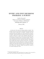
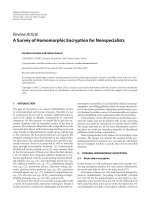
<i>system to convert the HC, CO and N O<small>x</small></i>emissions in the exhaust. This system may consist of several TWCswith different precious metal formulations (Pt and/or Pd, generally) and locations in the exhaust system tooptimize emissions performance. Figure 1 illustrates that high simultaneous conversion efficiencies for the
<i>three species occur only in a narrow band around stoichiometry, emphasizing the criticality of A/F control</i>
to minimizing tailpipe emissions. An overview of the challenges related to emissions control in the designand development of powertrain control systems for modern passenger vehicles may be found in [7].
Considerable effort as well is made to minimize engine out emissions to reduce the amount of costly
<i>precious metal required in the TWC. Typically, N O<small>x</small></i> reduction is accomplished by reducing combustiontemperature through exhaust gas recirculation (EGR). EGR can be introduced externally via a valve thatconnects the intake and exhaust manifolds, or internally via variable camshaft timing (VCT) control. VCTcan improve fuel economy in addition to reducing emissions, but presents control challenges that arise fromdynamic interactions in the engine breathing process.
</div><span class="text_page_counter">Trang 3</span><div class="page_container" data-page="3"><small>14.214.414.614.8MEAN A/F</small>
<i>Figure 1: TWC conversion efficiency versus A/F</i>
Turbocharged engines present similar challenges. The torque developed by a conventional gasoline engine
<i>is proportional to the air supplied to the cylinders, because the A/F is controlled to stoichiometry. In a</i>
turbocharged engine, the density of the cylinder air charge is increased. Consequently, engine displacement
<i>may be reduced at equivalent power, providing improvements to CO</i><small>2</small>emissions and fuel economy. To achievethese benefits in a modern engine requires coordinated control of the throttle and wastegate actuators.
The following subsection will provide a brief review of models for the PFI engine and the TWC
<i>aftertreat-ment system. Control problems for A/F regulation, VCT torque manageaftertreat-ment, and turbocharged gasoline</i>
engines will also be discussed.
2.1PFI Engine and Aftertreatment Models
A great deal of literature over many years describes the development of “control oriented” engine models: thatis, linear and nonlinear low frequency phenomenological representations that capture the essential systemdynamics required for control development, along with key static behavior such as emissions and volumetricefficiency that may be obtained experimentally from steady state mapping on an engine dynamometer.Fundamental models were developed from the late 1970s through the 1980s as reported in [8, 9, 10, 11,12, 13, 14]. The four-stroke engine cycle naturally divides the physical process into four events comprisingintake, compression, power generation and exhaust. Models exploiting the inherently discrete nature of thesystem by crank angle based sampling are described in [15, 16, 17, 18, 19, 20].
2.1.1 The Fundamental PFI Engine Model
The mathematical representation of the conventional, naturally aspirated engine includes the following ements: (1) the throttle body, (2) the intake manifold, (3) torque generation and (4) engine rotationaldynamics. The model may also include the EGR system, exhaust gas temperature and pressure dynamics,and feedgas emissions. The intake manifold dynamics are derived from the ideal gas law:
<i>where K<small>i</small>depends on the intake manifold volume and temperature, W<small>a</small>, W<small>egr</small></i> are the mass flow rates through
<i>the throttle body and the EGR valve respectively; and W<small>cyl</small></i> is the mean value of the flow rate at which the3
</div><span class="text_page_counter">Trang 4</span><div class="page_container" data-page="4">charge is inducted into the cylinders. The flows through the throttle body and EGR valve are representedby a standard orifice equation:
<i>W<small>a</small></i>= <i><sup>A</sup>√<sup>th</sup><sup>P</sup><sup>i</sup>T<small>a</small></i>
<i>, W<small>egr</small></i>= <i><sup>A</sup>√<sup>egr</sup><sup>P</sup><sup>e</sup>T<small>e</small></i>
<i>where A<small>th</small>, A<small>egr</small>are the effective flow areas for the throttle body and EGR valve respectively; P<small>i</small>, P<small>e</small></i>, and
<i>P<small>a</small>are intake manifold, exhaust manifold and ambient pressures; T<small>a</small>and T<small>e</small></i> are the ambient and exhaust
<i>temperatures. The function φ represents the effects of the pressure ratio on the flow across the valve:</i>
<i>φ(x) =</i>
<i>γ</i><sup>1</sup><sup>³</sup> <small>2</small>
´ <i><small>γ+12(γ−1)</small></i>
<i>if x ≤</i><sup>³</sup> <small>2</small>
´ <i><small>γγ−1</small></i>
<i>where γ is the ratio of specific heats, which takes different values for W<small>a</small>and W<small>egr</small></i>.
<i>The amount of charge inducted into the cylinders, W<small>cyl</small></i>, is a function of engine speed, intake manifoldpressure and, possibly, temperature, where intake manifold temperature depends on mass air flow and EGR.
<i>W<small>cyl</small></i> is generally represented as a static regression equation based on steady-state mapping data for aparticular engine.
Engine rotational dynamics follow the equation:
<i>where T<small>b</small>, T<small>l</small>are the engine brake and load torque in N m, respectively, and the factor π/30 is due to theunit conversion of engine speed, N , (from rpm to rad/sec). The engine brake torque, T<small>b</small></i>, is the net torqueavailable on the crankshaft to drive the rest of the powertrain, and can be decomposed into:
<i>where T<small>i</small></i>is the indicated torque, a measure of the total torque delivered to the piston by burning the fuel and
<i>T<small>f</small></i> is the total friction which the engine has to overcome when delivering the torque to the crankshaft. Thefriction torque includes the pumping losses during the intake and exhaust strokes plus mechanical frictionand may be regressed as a function of engine speed and intake manifold pressure. Brake torque is generally
<i>represented as a regressed function of W<small>cyl</small>, A/F , N , and ignition timing.</i>
2.1.2 Three-way Catalyst Model
Control oriented models of the TWC generally incorporate two parts: an oxygen storage mechanism to
<i>account for the modification of the feedgas A/F as it passes through the catalyst, and the standard state efficiency curves driven by the tailpipe A/F computed from the oxygen storage model [21, 22, 23, 24].</i>
steady-The following model is taken from [21].
<i>First, consider the oxygen storage sub-model. Let 0 ≤ Θ ≤ 1 be the fraction of oxygen storage sites</i>
occupied in the catalyst. Θ is also referred to as the TWC oxygen loading. The oxygen storage mechanismis then modeled as a limited integrator:
˙Θ =
<i>where W<small>a</small></i> denotes the mass air flow rate, used to approximate the flow rate of the mixture entering the
<i>TWC and τ is used to account for the transport delay. C represents the effective catalyst “capacity,” or</i>
the volume of active sites for oxygen storage, expressed in terms of the mass of oxygen that can be stored
<i>in the catalyst, as a function of W<small>a</small>; ρ describes the exchange of oxygen between the exhaust gas and thecatalyst; and λ denotes the relative air-fuel ratio, with stoichiometry at λ = 1 (the subscript F G refers to</i>
the feedgas).
</div><span class="text_page_counter">Trang 5</span><div class="page_container" data-page="5"><i>The effective TWC volume parameter, C, is expressed as a function of W<small>a</small></i> in order to account for anobserved increase in effective volume at high flow rates, specifically above 10 g/s. For clarity, it should be
<i>emphasized that C does not represent the physical volume of the catalyst, often sized according to the engine</i>
displacement. For example, if there were no usable storage sites (i.e., if they were poisoned by substances
<i>such as sulfur or phosphorus), then C would be zero.The oxygen storage function ρ is modeled as</i>
<i>ρ(λ<small>F G</small>, Θ) =</i>
<i>α<small>L</small>f<small>L</small></i>(Θ) <i>λ<small>F G</small>> 1</i>
<i>with 0 ≤ f<small>L</small>≤ 1 representing the fraction of oxygen from the feedgas attached to a site in the catalyst,</i>
<i>and 0 ≤ f<small>R</small>≤ 1 representing the fraction of oxygen being released from the catalyst and recombining with</i>
<i>the feedgas. In the oxygen storage function, f<small>L</small>and f<small>R</small></i>vary with the TWC oxygen loading and potentiallywith the space velocity (that is, the feedgas volumetric flow rate divided by the catalyst volume). In the
<i>model, f<small>L</small>is assumed to be monotonically decreasing, with value one at Θ = 0 and zero at Θ = 1, and f<small>R</small></i> isassumed to be monotonically increasing, with value zero at Θ = 0 and one at Θ = 1.
<i>The quantity 0.23 × W<small>a</small>× (1 −</i> <small>1</small>
<i><small>λF G</small></i>) represents the differential total mass of oxygen in the feedgas with
<i>respect to stoichiometry. When multiplied by ρ, it gives the mass of oxygen that is deposited in (or releasedfrom) the catalyst. By conservation of mass, the resulting equivalent tailpipe A/F can be directly computed:</i>
2.2A/F Control for PFI Engines
<i>Three main problems arise in A/F control of the conventional PFI engine: accurate estimation of air charge,</i>
compensation for fuel puddling dynamics in the intake manifold runners and precise regulation of closed-loop
<i>A/F for good catalyst performance. A low frequency model of the induction process is described in [25],</i>
and compensation is developed for the relatively slow dynamics of the conventional hot-wire anemometerused to measure inlet air flow. In [26], a dynamic model incorporating intake runner acoustic and inertialeffects is developed that is capable of describing the induction process in individual cylinders. Transient fuelcharacteristics for a PFI engine were first reported by Fozo and Aquino in [27]. In [28, 29], a method ofadaptive transient compensation for fuel wall-wetting dynamics is described that accounts for varying fuelproperties. The technique requires only a heated exhaust gas oxygen (HEGO) sensor, which remains the
<i>prevalent feedback sensor for closed-loop A/F control. A HEGO sensor is essentially a switch, indicatingthat the A/F mixture is either rich or lean of stoichiometry, but not by how much. The basic idea of [28] isto use the feedback signal to evaluate changes in A/F during driver induced transients in closed loop, and</i>
store corrections to the compensation algorithm indexed by engine temperature for use in the next transientor during open-loop cold start operation.
<i>In [30], it was shown that cylinder-to-cylinder A/F differences result in a closed-loop lean shift in trolled A/F due to preferential diffusion of H</i><small>2</small> <i>and CO across the HEGO sensor upstream of the catalyst.This control-point shift causes a dramatic reduction in N O<small>x</small></i>conversion efficiency due to the precipitous na-ture of the TWC characteristic away from stoichiometry (see Figure 1). Typically, this effect is mitigated by
<i>con-biasing the A/F setpoint slightly rich, at a cost in fuel economy and conversion efficiency of the other exhaustconstituents. In [31], an approach to achieving uniform cylinder-to-cylinder A/F control for a 4-cylinder</i>
engine in the presence of injector mismatch and unbalanced air flow due to engine geometry is presented. Themethod recognizes that the individual cylinder representation of the fueling process describes a periodically
<i>time varying system due to the unequal distribution of A/F from cylinder to cylinder. The key features of</i>
the controller are the construction of a time-invariant representation of the process and event-based samplingand feedback. In [32], the method was extended to an 8-cylinder engine in which exhaust manifold mixingdynamics were significant.
<i>A significant advancement in A/F feedback control capability is the introduction in production vehicles</i>
of the Universal Exhaust Gas Oxygen (UEGO) sensor. Unlike the conventional HEGO sensor which simply
<i>switches about stoichiometry, the UEGO is a linear device that permits an actual measurement of A/F .</i>
5
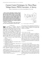
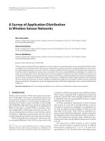
</div><span class="text_page_counter">Trang 6</span><div class="page_container" data-page="6">A review of electrochemical sensor technology may be found in [33]. Control and diagnosis of catalystsusing UEGO sensors are described by [34, 35]. In [36, 37], Fiengo and co-authors use the catalyst modeldescribed above along with pre- and post-catalyst UEGO sensors to develop a controller with two objectives:
<i>to simultaneously maximize the conversion efficiencies of HC, CO and N O<small>x</small></i>, and to obtain steady-state fuel control that is robust with respect to disturbances. A series controller topology is adopted as illustrated
<i>air-in Figure 2. The objective of the first block, the Fore Controller, is to respond relatively quickly to A/Fdisturbances on the basis of measured feedgas oxygen level. The objective of the second block, the Aft</i>
<i>Controller, is to adjust the setpoint of the fore controller, on the basis of both A/F measurements, so</i>
<i>that the TWC achieves simultaneously high conversion efficiencies for HC and N O<small>x</small></i>. The aft controller iscomposed of a bias estimator and a proportional term. The bias estimator uses the upstream and downstream
<i>A/F measurements to correct the error in the upstream oxygen sensor. The proportional controller feeds</i>
back the post-catalyst UEGO sensor measurement and establishes the reference for the fore controller.
Fore
Figure 2: Dual UEGO Fore-Aft Controller
2.3Control of Engines with Variable Cam Timing
Variable cam timing provides improved performance and reduced feedgas emissions using an electro-hydraulicmechanism to rotate the camshaft relative to the crankshaft and retard cam timing with respect to the intakeand exhaust strokes of the engine. In this manner, the amount of residual gas trapped in the cylinder at the
<i>end of the exhaust stroke is controlled, suppressing N O<small>x</small></i> formation [38, 39, 40]. In addition, VCT allowsthe engine designer to optimize cam timing over a wide range of engine operating conditions, providingboth good idle quality (minimal overlap between the intake and exhaust events) and improved wide-openthrottle performance (maximum inducted charge). Obviously, variable cam timing has a substantial effecton the breathing process of the engine. Properly controlled, the variable cam can be used to operate theengine at higher intake manifold pressures, reducing pumping losses at part throttle conditions to provide afuel economy improvement. Uncompensated, however, VCT acts as a disturbance to the breathing process,compromising drivability and substantially reducing its effectiveness in reducing emissions.
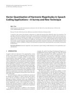
Four versions of VCT are available: phasing only the intake cam (intake only), phasing only the exhaustcam (exhaust only), phasing the intake and exhaust cams equally (dual equal), and phasing the two camshaftsindependently (dual independent). A low order nonlinear model of a dual-equal VCT engine is derived in[41]. In [42], the model forms the basis for active compensation of VCT induced cylinder air charge variationemploying electronic throttle control (ETC). The balance of this section will review the VCT model anddescribe the ETC compensation.
The basic equations of the VCT engine model are the same as those in Section 2.1, modified to incorporatethe effects of the cam actuator on engine breathing. For the VCT engine, the mass air flow rate into the
<i>cylinders is represented as a function of cam phasing, ζ<small>cam</small>, in addition to manifold pressure, P<small>i</small></i>, and engine
<i>speed, N :</i>
</div><span class="text_page_counter">Trang 7</span><div class="page_container" data-page="7">-Figure 3: Engine model with VCT and electronic throttle
<i>which, for the design model of [42], is approximated by a function affine in P<small>i</small></i>:
<i>where α</i><small>1</small><i>and α</i><small>2</small> <i>are low-order polynomials in N and ζ<small>cam</small></i>.
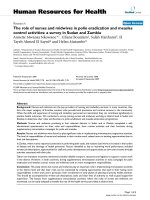
<i>A block diagram of the VCT engine is illustrated in Figure 3, which shows the cam timing reference, ζ<small>ref</small></i>,
<i>scheduled on engine speed and driver demanded throttle position, θ</i><small>0</small>. Typically, the cam schedule reachesmaximal cam retards at part throttle to provide maximal internal EGR; close to idle and at wide openthrottle, the cam phasing is at zero or slightly advanced. Scheduling cam on throttle causes it to changewhen the pedal is depressed or released. It is this torque variation caused by the cam transient that resultsin undesirable engine response and drivability problems. Note that the throttle angle is comprised of the
<i>throttle position due to the driver’s request (θ</i><small>0</small><i>) and an additive term due to the compensation (θ<small>∗</small></i>),
<i>θ = θ</i><small>0</small><i>+ θ<small>∗</small>.</i>
<i>The throttle flow equation is represented as functions of pressure and flow area geometry, φ(P<small>i</small>)g(θ), as in</i>
the conventional engine model.
A feedforward compensator is designed to recover the drivability of the conventional engine by eliminating
<i>the effect of the cam transients on cylinder mass air flow. The algorithm employs θ<small>∗</small></i> as a virtual actuator,
<i>according to [42]. That is, a control law is developed for θ<small>∗</small>such that the rate of change of W<small>cyl</small></i> coincides
<i>with that of the conventional engine. Specifically, compensation θ<small>∗</small></i>is evaluated:
<i>θ<small>∗</small>= g<small>−1</small></i>
à <i><sub>∂α</sub></i><small>1</small>
where ˜<i>P<small>i</small></i> is a fictitious reference manifold pressure which should be equal to the manifold pressure of the
<i>conventional engine driven with the throttle angle, θ</i><small>0</small><i>, and engine speed, N . This reference manifold pressure</i>
2.4Control of Turbocharged Gasoline Engines
Turbocharging is an efficient method to boost intake pressure, as it extracts energy from the exhaust gasesto drive a compressor to pressurize ambient air. In automotive applications, operating conditions vary overa wide range of speed and load. A design challenge is to develop a system that provides adequate boost at
7
</div><span class="text_page_counter">Trang 8</span><div class="page_container" data-page="8"><small>Time (s)</small>
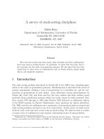
<small>Conventional Engine (base timing)</small>
<small>VCT Engine - controller off</small>
Figure 4: Torque response of the VCT engine to cam phasing steps with and without compensation
low speed and load without creating an over-boost situation at high speed and loads [44]. Typically, theamount of boost delivered by a turbocharger is controlled by a wastegate.<small>1</small> In any event, the advantages ofturbocharging are accompanied by an increase in complexity of the control design and calibration.
Complexity is also introduced by other phenomena associated with turbocharging. For example, ing charge density increases propensity for engine knock, particularly at high loads. This phenomenon isalleviated in many applications by passive or active thermal management with a charge cooling device, suchas an intercooler. In conventional gasoline engines, knock is further controlled by spark retard [45]. In directinjection engines, fuel injection control may also provide some benefit [43].
increas-Transient response is another factor, as turbocharger inertia leads to a phenomenon known as “turbolag”. Turbo lag describes the delay in torque response due to the time required for the turbocharger tochange speed and thus affect boost pressure. Control objectives for fast response to minimize this effect aretempered by limits on boost pressure overshoot, which can lead to unacceptable torque disturbances [46],[47].
Modern turbocharged gasoline engines have advanced technology actuators such as electronic throttleand variable valve timing, in addition to the wastegate. Coordinated control of these actuators is criticalto achieve the full benefit of these combined technologies. Historically, literature that pertains to wastegatecontrol in gasoline applications, such as [48, 49, 45], refer to systems with a mechanical throttle. Morerecently, control with advanced actuators has received significant attention. Apart from [46, 47], however, thefocus has been on the turbocharged diesel engine (for example see [50, 51, 52]). Most of these results cannotbe applied directly to the gasoline engine due to fundamental differences in actuators and system performanceobjectives. A notable exception is control oriented component modeling, for example the turbocharger modelpresented in [53]. Such component models are key to the system level models of turbocharged gasoline enginesdeveloped in [54, 55, 56].
Such control oriented models are all based, in principle, on the fundamental PFI engine model cussed in Section 2.1. The basic engine model is augmented with mathematical expressions representing a
<small>dis-1Other advanced technology devices, for example variable geometry turbochargers that directly control turbine or compressorflow are under development by automotive suppliers [43]. Such devices have had application in diesel engines but are currentlyunsuitable for the high exhaust temperature environment of gasoline engines.</small>
</div><span class="text_page_counter">Trang 9</span><div class="page_container" data-page="9">Figure 5: Schematic diagram of a turbocharged gasoline engine.
turbocharger, with wastegate and an intercooler.
A schematic diagram of a turbocharged gasoline engine is shown in Figure 5. The representation of theturbocharger consists of models of the compressor, turbine and wastegate, and includes the dynamic coupling
<i>of the compressor and turbine. The mass flow rate through the compressor, W<small>c</small></i>, is described by
<i>W<sub>c</sub>= f<sub>c</sub></i>
<i>, N<sub>tc</sub>, T<sub>a</sub></i>
<i>where P<small>b</small>is the compressor exit pressure, typically referred to as boost pressure, P<small>a</small>and T<small>a</small></i>are the compressor
<i>inlet conditions, which in most cases are assumed to be ambient, and N<small>tc</small></i> is the turbocharger shaft speed.The compressor exit temperature can be calculated as
<i>T<small>c</small>= T<small>a</small></i>
"1 + <sup>1</sup>
<i>where, c<small>p,c</small></i> is the specific heat at constant pressure of the air in the compressor.
<i>The turbine is described in a similar fashion. The mass flow through the turbine, W<small>t</small></i>, is modeled as
<i>where P<small>e</small>and T<small>e</small></i>are the pressure and temperature at the inlet of the turbine, respectively, which are typically
<i>assumed equal to the exhaust manifold conditions, and P<small>t</small></i>is the turbine exit pressure.The turbine exit temperature is given by
<i>T<small>t</small></i> ="
9
</div><span class="text_page_counter">Trang 10</span><div class="page_container" data-page="10"><i>where η<small>isen</small></i>
<i><small>t</small></i> is the isentropic efficiency of the turbine.
<i>The power generated by the turbine, P ower<sub>t</sub></i>, is calculated from the first law of thermodynamics,
<i>P ower<small>t</small>= c<small>p,t</small>W<small>t</small>(T<small>e</small>− T<small>t</small>),where c<small>p,t</small></i> is the specific heat at constant pressure of the gas in the turbine.
The dynamics of the turbocharger shaft are given by˙
<i>N<small>tc</small></i>= <i><sup>P ower</sup><sup>t</sup><sup>− P ower</sup><sup>c</sup></i>
<i>where J<small>tc</small></i> is the inertia of the turbocharger.
The wastegate can be modeled with the standard orifice flow equation, as described in (3). Measurementsneeded to derive the effective orifice area may be difficult to obtain; nonetheless, an effective model can bedeveloped with selected use of estimated variables, such as exhaust flow rate.
Model integration requires an exhaust manifold model and a model to represent the volume between thecompressor and the throttle. Both volumes are typically modeled in a fashion similar to (1), with variationsto account for temperature dynamics and/or heat transfer [55, 57], depending on the application.
A turbocharged system model of this type is used by the authors of [46] to analyze system tics and develop charge control algorithms for a wastegated turbocharged system equipped with electronicthrottle. Boost pressure and intake manifold pressure are both measured and conventional decentralized PIcontrol with feedforward on the wastegate is used to regulate these measured variables to desired setpoints,which are chosen to achieve fuel economy, emissions and driveability objectives. The control structure isshown in Figure 6.
Figure 6: Block diagram of decentralized boost control
This approach produces acceptable performance, however the wastegate is prone to saturation. variable control techniques can be used to analyze the system to guide formulation of a modified controllerthat maintains a simple structure desirable for implementation, and yet benefits from a centralized controlmethodology. Such an approach is described in [58]. This technique reformulates full state feedback integralcontrol as an output feedback control by
<i>Multi-C<small>eq</small></i>=<sup>³</sup><i>−K<small>sf</small>(sI − (A − BK<small>sf</small></i>))<i><sup>−1</sup>B + I´ K<small>i</small></i>
<i>where K<sub>sf</sub>is the gain corresponding to the plant states and K<sub>i</sub></i>is the gain corresponding to the error states.
<i>Both are obtained from full state feedback design. A and B are matrices appearing in a state-variable</i>
representation of a linear model of the sytem.
<i>This C<small>eq</small></i> controller is examined to identify prominent behavior. Key controller characteristics are ulated with simple linear elements such as low- and high-pass filters, to achieve an approximation of themultivariable controller. Although robustness to unmeasured disturbances needs to be further explored, asimplified controller that exhibits some of the characteristics of the multivariable control is obtained.
</div><span class="text_page_counter">Trang 11</span><div class="page_container" data-page="11">em-3Lean Burn and Direct Injection Gasoline Engine Control
Lean-burn engines may be a major enabling technology for improving fuel economy of gasoline engines.Engines operated with lean mixtures have lower throttling losses at low and part loads, resulting in reduced
<i>(up to 15%) fuel consumption and CO</i><small>2</small>generation. The major technical hurdles in extending the lean-burn
<i>limit of a PFI engine are combustion stability and N O<small>x</small></i>treatment. While the lean limit of a conventionalPFI engine has been significantly extended by advanced combustion concepts (such as those that induce
<i>high turbulence), the maximum A/F that can be achieved in PFI engines without compromising other</i>
performance indices is around 22. This limit is substantially extended by direct injection and stratificationmade possible by technical advances in high-pressure fuel injection and combustion chamber design. The
<i>issues of N O<small>x</small></i> emissions associated with lean-burn (port or direct injected) engines arise because of the factthat conventional three-way catalysts are ineffective for air-fuel ratios even slightly lean of stoichiometry.
<i>Consequently, lean-burn engines use an actively controlled emission device called a lean N O<small>x</small></i> trap (LNT)
<i>to meet N O<small>x</small></i> emission standards. The incorporation of the LNT adds both cost and complexity, makingoptimization and trade-off analysis the predominant tasks for control and integration of lean-burn gasolineengine systems.
In this section, we will focus on the following three main control problems and their solutions for directinjection stratified charge (DISC) engines equipped with LNT: (1) mode transition, (2) aftertreatment controland adaptation, (3) system optimization and integration. While the port fuel injected lean burn enginecontrol problems will not be explicitly addressed here, it should be noted that the issues and solutions fordirect injection engines are applicable to PFI lean-burn engines as well, with minor modification.
3.1Unique Features and Control Implications of DISC Powertrain System
A DISC engine, like a diesel, injects fuel directly into the combustion chamber. It is different from aconventional PFI engine discussed in Section 2 in several respects. Most importantly, the DISC enginecan, depending on speed and load, operate in one of three combustion modes: homogeneous stoichiometric
<i>(A/F ≈ 14.64), homogeneous lean (between stoichiometry and about 20) or stratified (≥ 20). A homogeneous</i>
<i>A/F mixture is achieved by injecting fuel early in the intake stroke, while stratification is achieved by</i>
injecting late, during the compression stroke [59]. The torque and emission characteristics corresponding tohomogeneous and stratified operation are so distinct that different control strategies are required to optimizeperformance in the two regimes [60, 61]. Note also that, in addition to the usual control variables such asthrottle position, ignition timing, exhaust gas recirculation (EGR) and fueling rate, the DISC engine requiresnew inputs including injection timing, fuel rail pressure and swirl control at a minimum [62]. Finally, the
<i>ultra-lean A/F operation of the direct injection engine mandates the use of a lean N O<small>x</small></i> trap (LNT) to
<i>manage oxides of nitrogen emissions. The LNT, as a N O<small>x</small></i> storage device, needs to be purged periodicallyto regenerate its storage capacity.
These special features of DISC engine operation have important control implications and lead to thefollowing unique control problems:
<i>• Mode transition: Depending on engine operating and LNT loading conditions, the DISC engine will</i>
either operate in stratified or homogeneous mode or switch between the two modes. The control mustbe capable of changing the combustion mode and the air-fuel ratio of the engine rapidly without causingnoticeable disturbance to the driver.
<i>• Aftertreatment control: The requirements for the aftertreatment control include (1) periodically </i>
run-ning the engine rich of stoichiometry to regenerate its trap capacity, (2) dealing with the sulphurpoisoning problem to maintain its efficiency, and (3) assuring that the LNT operates within its tem-perature window to maintain high efficiency and to avoid thermal degradation.
<i>• Optimization and trade-off analysis: The inclusion of the storage device in the aftertreatment system</i>
changes the nature of the optimization problem. The interactive characteristics of the subsystemsinvolved, together with the time and trajectory dependent nature of LNT operation, result in a high
11
</div><span class="text_page_counter">Trang 12</span><div class="page_container" data-page="12">dimensional and dynamic optimization problem that demands new computational methodologies andtools.
The engine and aftertreatment models, to be discussed in the following subsection, facilitate the model-basedtreatment of these problems.
3.2DISC Engine and Its Aftertreatment System Models
3.2.1 DISC Engine Model
References [60, 61] describe modeling and control of a direct injection stratified charge (DISC) gasoline engineand discuss the fundamentally hybrid nature of the system. This model is illustrated in Figure 7. On thesurface, the model structure is not dissimilar to a conventional PFI engine discussed in Section 2, consistingof the throttle, intake manifold dynamics, engine pumping, torque generation, rotational inertia and feedgasemissions. In fact, many of the equations used to describe the PFI engines in Section 2 can be applied here.Because of the different characteristics for homogeneous and stratified operation, the model is, in fact, hybridin the sense that most components are represented by two continuous-variable sub-models with a discreteswitching mechanism to select the appropriate characterization based on injection timing. Additionally, theinjection-to-torque delay, fundamentally associated with the four-stroke engine cycle (intake-compression-power-exhaust), becomes a function not only of engine speed, but also of the operating mode that dictatesthe relationship between the injection and combustion events.
<small>Air Path</small>
<small>Delay</small> <sup>Engine</sup><small>TorqueDelayFuel PathSpark</small>
<small>Injection Timing</small>
<small>g (P,N)Engine Pumping</small>
<small>Manifold DynamicsThrottle Body</small>
<small>and ABV+</small> <sub>+</sub>
<small>-.meSABV DC</small>
<small>Pf (u,P)</small>
Figure 7: Block diagram of DISC engine model
3.2.2 Lean Aftertreatment Model
The typical aftertreatment system for a lean-burn engine with a commonly used sensor configuration isshown in Figure 8. It consists of a conventional three-way catalytic converter (usually closely coupled to theengine for optimal cold start performance) and an underbody LNT, with oxygen and temperature sensorsin various locations.
<i>The key chemical reactions involved in the LNT operation can be briefly discussed as follows. N O<small>x</small></i>storage
<i>phase: under lean conditions, N O is oxidized in the gas phase and the resulting N O</i><small>2</small> is then adsorbed on
<i>storage sites such as barium nitrate. As the N O<small>x</small></i>stored in the LNT increases, the storage efficiency dropsand the trap must be purged to regenerate its capacity. LNT purge phase: under rich conditions, the barium
<i>nitrate becomes thermodynamically unstable and releases N O</i><small>2</small><i>and BaO. BaO then combines with CO</i><small>2</small> in
<i>the exhaust to form BaCO</i><small>3</small><i>, thereby regenerating the storage sites. The released N O<small>x</small>is converted to N</i><small>2</small>
<i>over the precious metal sites by reductants (CO or H</i><sub>2</sub>) in the engine exhaust stream.
A control oriented representation of the LNT exhaust aftertreatment system was first developed in [63].
<i>In this model, the amount of N O<small>x</small>stored on the LNT is a state. Under lean conditions, the N O<small>x</small></i> storage
<i>capability is modeled by a limited integrator with the storage rate of N O<small>x</small></i>being a monotonically decreasing
</div><span class="text_page_counter">Trang 13</span><div class="page_container" data-page="13"><i>f<small>s</small>(x, W<small>N Ox,in</small>, T<small>LN T</small>) if λ<small>r</small>≥ 1 & x ≤ 1f<small>p</small>(x, W<small>CO,in</small></i>) <i>if λ<small>r</small>< 1 & x ≤ 1</i>
<i>where the functions f<small>s</small>, f<small>p</small></i> model the store and purge operation of the LNT, respectively. The flow rates
<i>W<small>N Ox,in</small>and W<small>CO,in</small>are the inlet mass flow of N O<small>x</small>and CO, and λ is the relative air-fuel ratio entering</i>
the LNT.
In [64], the model is extended by modifying the purge model to capture the interactions between the
<i>oxy-gen storage and N O<small>x</small></i>storage mechanisms in the LNT. By separately modeling the releasing and conversion
<i>reactions during the purge phase, the integrated model is able to replicate experimentally observed N O<sub>x</sub>spikes during the purge phase [65]. In another modification to the original model, air-fuel ratio, λ, is usedinstead of W<small>CO,in</small>in the functions that represent the N O<small>x</small></i>release rate and conversion efficiency, making themodel more amenable to control implementation.
3.3Mode Transitions for DISC Engine Control
Typically, stratified operation is limited to low- and part-load engine operating conditions where the imum fuel economy benefits of a DISC engine can be achieved. At increasing loads, stratified combustionoften results in increased smoke and hydrocarbon emissions, requiring a switch to homogeneous operation.Similarly, as the engine speed increases, a mode switch is also necessary as the time for mixing and breathingis reduced, making it infeasible to operate in stratified mode (stratified operation requires more air charge).Finally, the LNT aftertreatment system needs to be purged periodically to maintain high efficiency, andthis is accomplished by transitioning to an air-fuel ratio slightly rich of stoichiometry. Consequently, modeswitching between stratified and homogeneous combustion may be initiated not only when the engine torquedemand increases, but also when the torque demand is small and constant, such as when the engine is idling.The mode transitions have to be accomplished in a manner that does not create a disturbance noticeableby the driver, while providing the desired value of the engine torque throughout the transition. In [66], a
<i>max-hybrid control scheme is presented to manage the transition. The controller consists of a high level </i>
<i>Transi-tion Governor that is used to determine the combusTransi-tion mode and the setpoints, and a low level feedback</i>
controller that coordinates the spark timing, throttle, and fuel injection to ensure the desired value of theengine torque throughout the transition. In [61], the coordinating control is derived by minimizing the costfunction:
<i>which participates in combustion and must, therefore, be estimated. T<small>d</small>, λ<small>d</small>, δ<small>d</small>and F<small>d</small></i>
<i><small>bg</small></i>are setpoint values,13
</div><span class="text_page_counter">Trang 14</span><div class="page_container" data-page="14"><i>determined by the Transition Governor. The multipliers γ</i><small>1</small> <i>through γ</i><small>3</small> are relative weighting factors thatdepend on operating condition. For example,
<i>• γ</i><small>1</small><i>À 1 when λ<small>d</small>= stoichiometry and A/F control is the highest priority objective.</i>
<i>• γ</i><small>2</small> <i>À γ</i><small>1</small> <i>for stratified or lean homogeneous operation. In this case, the A/F requirement is relaxed,</i>
but spark must be carefully managed within a limited range for combustion stability.
Other constraints on the minimization include manifold pressure (sufficient vacuum must be maintained tooperate vacuum controlled devices such as the power brake booster), the limits of authority of the throttle
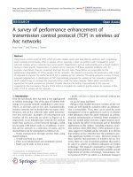
<i>and EGR valve, and allowable spark timing and A/F . Figure 9 shows typical A/F and torque traces on</i>
a small DISC engine for constant torque combustion mode transitions. In the case of a transition from
<i>homogeneous to stratified, the transient A/F requirement is relaxed, giving the fuel actuator substantial</i>
authority to maintain constant torque during the mode shift. On the other hand, the transition from stratified
<i>to homogeneous operation at stoichiometry requires tight control on A/F to meet emission requirements.Consequently, γ</i><small>1</small>is large, requiring torque management via spark, which has limited authority, and throttle,which is slow acting, resulting in slightly deteriorated control.
<small>Time (sec)</small>
<small>Time (sec)</small>
Figure 9: Constant torque DISC mode transition on an engine dynamometer. Homogeneous to stratifiedtransition (left) prioritizes torque control; stratified to homogeneous transition (right) relaxes the torque
<i>objective to ensure A/F control at stoichiometry</i>
The same control problem can also be solved using a Lyapunov based speed-gradient algorithm as in[66, 67], and hybrid model predictive control [68] which optimally coordinates the actuators over a recedinghorizon. Speed-gradient control is also used for coordinated throttle and EGR valve management in [69, 70].In [71], the continuously variable transmission (CVT) is exploited to provide an additional control actuationduring mode transitions to manage wheel torque and mitigate the effect of torque disturbances. The studyreveals, however, that an intuitively sound CVT gear ratio control strategy which attempts to completelycancel the engine torque disturbance, results in unstable zero dynamics. The same paper then proposesa control strategy that coordinates the engine control variables (spark and fuel) with the CVT gear ratiocontrol to stabilize the zero dynamics while achieving seamless mode transition.
The multi-mode operation of a DISC engine also brings new challenges for the standard idle speed controlproblem, as well as opportunities for improved engine idle performance. In [72] an idle speed controller isdesigned for a DISC engine by exploring the use of electronic throttle, spark and fuel. A hierarchical controlarchitecture is assumed, where a supervisory engine controller determines the combustion mode and thecorresponding setpoints for all actuators, and all other control features strive to meet the demands set forthby the supervisory controller. Two different controller topologies, referred to as speed-dominant and air-fuel
</div><span class="text_page_counter">Trang 15</span><div class="page_container" data-page="15">ratio dominant respectively, are developed to take advantages of the multi-mode nature of the DISC engine.Rapid completion of an LNT purge cycle was demonstrated while idling, even under considerable externalload disturbances. In [73], idle speed is formalized as a constrained optimal control problem where fuelconsumption is minimized. A sub-optimal, but easily implementable solution is obtained using a commandgovernor.
3.4Aftertreatment Control and Adaptation
To achieve the best tradeoff among competing requirements such as fuel economy, emissions and driveability,the LNT control strategy must manage the purge starting time, duration, and purge condition (such as
<i>A/F ), and at the same time provide a bumpless transition between the lean and purge modes. The main</i>
challenges of LNT control stem from the lack of on-board measurements of key variables and the uncertainties
<i>in the characteristics of the key components. The N O<small>x</small></i>storage capacity of the LNT, one of the most criticalparameters for control design and calibration, varies dynamically. In particular, the trap is susceptible tosulfur poisoning [74] and the capacity of the trap is reduced as sulfates accumulate. In addition, ambientconditions and component-to-component variations can affect the LNT operation and lead to deterioratedperformance.
In the absence of real-time measurements, the control of the aftertreatment has to rely on feedforward andmodel-based control, making the system performance vulnerable to uncertainties and model inaccuracies. In[75], it is shown that the parameters of the LNT model [63] can be identified on-line using a conventionalswitching exhaust gas oxygen sensor. For the model structure and uncertainty representations used in [75], anonlinear parametric model results. An on-line recursive algorithm is developed to improve the robustness ofthe model-based feedforward control and to ease the computational requirement of parameter identificationfor the nonlinear parametric model. Persistent excitation, a condition normally required for parameterconvergence, is established in [75] by changing purge thresholds.
In an effort to relax the computational intensity associated with the nonlinear parametric model usedin [75], a new purge model [64] is exploited by the authors of [76] to develop an adaptive control strategythat is more feasible for real-time implementation in a computationally resource-constrained environment.By incorporating the physical properties of the system and properly choosing the structure for the LNTmodel and parameterization for the uncertainties, a linear parametric model is developed in [76] for on-lineadaptation. Results show that, when integrated with model-based LNT control, the adaptation improves theaftertreatment control robustness by maintaining the desired tradeoffs between fuel economy and emissions.
3.5System Optimization and Integration
<i>For the DISC powertrain system incorporating N O<small>x</small></i>storage, a dynamic optimal control problem has to beformulated, because fuel consumption and emissions, evaluated over a specified driving cycle, are not simplyfunctions of the instantaneous speed-load point, but of the operating history of the engine. The high degree offreedom introduced by the multiplicity of the control variables, coupled with time and trajectory dependency,leads to a very high dimension optimization problem. In [77, 78] a method is introduced that dramaticallyreduces the computational burden of dynamic programming to make model-based design decisions for thelean-burn DISC powertrain. Results showing the sensitivity of the fuel economy performance objective atEuropean Stage IV emission standards with respect to physical aftertreatment parameters, including the
<i>amount of oxygen storage in the TWC and the capacity of the lean N O<small>x</small></i> trap, are presented. In anothertrade-off study, control complexity is evaluated with respect to emissions benefit. Specifically, the optimalfuel economy, constrained by Stage III and Stage IV requirements, is evaluated to show the potential effectsof eliminating the homogeneous lean combustion mode. It is determined, as illustrated in Figure 7 of [62],
<i>that as N O<small>x</small></i> emission requirements become more stringent, the benefits of operating the engine in thehomogeneous lean mode become less appreciable, up to a point where the incremental benefits may not beenough to justify the additional complexity.
The most important contributions of [77, 78] are methodological. In particular, the computationallyintense dynamic programming algorithm is rendered tractable by model simplification, state descretization,and analysis-based restriction on the search trajectories (called “calibrations”) along with careful treatment
15
</div><span class="text_page_counter">Trang 16</span><div class="page_container" data-page="16">of computational details. The dynamic programming problem for a two-state system (TWC plus LNT) overan emissions drive-cycle was reduced to 40 minutes from 60 hours, while still achieving a near-optimal solutionas shown in Figure 10. These results are similar to the system optimization problems of hybrid vehicles,which will be discussed in more detail in Section 6. Stochastic dynamic programming and game-theoreticmethods are explored for this purpose in [79, 80].
Using dynamic programming, the authors of [81] also explore the benefits of air-fuel ratio profiling in
<i>achieving improved fuel economy, N O<small>x</small>and HC emissions tradeoffs. By allowing A/F to vary during thepurge phase, they show that substantial leverage can be achieved in reducing HC and N O<small>x</small></i> emissions,without a negative impact on fuel economy.
<small>Optimization with calibrations </small>
<small>Stage IV NOx standard </small>
<i>Figure 10: Fuel economy versus N O<small>x</small></i> emissions of optimal policy with calibrations and full optimization
<i>over the Euro-cycle. The DISI engine and aftertreatment models are quasi-static. The LNT N O<small>x</small></i>filling andemptying is dynamically updated.
4Control of Automotive Diesel Engines
Diesel engines offer superior fuel economy compared to their conventional gasoline counterparts. Theirdrawbacks are associated with higher cost, and complexity of the aftertreatment system. Despite an earlierskepticism by even some of their developers<small>2</small>, diesel engines have achieved a remarkable passenger car marketpenetration in Europe thanks to technology improvements. The consensus is that their penetration in NorthAmerica will grow too, albeit at a slower pace due to differences in fuel cost and taxation.
Diesel engines are typically turbocharged or supercharged to improve power density. A variable geometryturbocharger (VGT) enables optimal “sizing” of the turbine for each engine operating condition by openingor closing inlet guide vanes [82], resulting in both improved fuel economy and engine responsiveness. Electricboosting assist devices [83] have been developed for this purpose as well.
Diesel engines, operated on the compression ignition principle, have many different features comparedto spark ignited gasoline engines. In particular, the following characteristics of diesel engines have strong
<i>control implications. First, they operate lean (A/F must usually stay above 22), and therefore require adifferent aftertreatment system. Second, N O<small>x</small></i>control, to a much greater extent compared to conventionalgasoline engines, relies on high EGR which, due to the lean operation, can contain significant amounts of
<small>2Sir Harry Ricardo stated in 1925 that “...the exhaust from diesel engines ... has a characteristic pungent and disagreeablesmell... the author cannot believe that the police will allow any large proportion of diesel-engined vehicles in the streets of, say,London.”</small>
</div><span class="text_page_counter">Trang 17</span><div class="page_container" data-page="17">combustible air. Third, the fueling rate is an independent and fast actuator for torque management, as long
<i>as the A/F is maintained within its limits. Modern common rail fuel injection systems permit fuel rate</i>
shaping and multiple injections per cycle for torque, noise and emission controls.
4.1Diesel Engine Models
Mean value models and cylinder-by-cylinder diesel engine models have been utilized for control system designand validation. Mean value modeling of diesel engines has been covered in the review articles [84, 85] andin the book [6], while the cylinder-by-cylinder modeling is addressed in [85] and [86]. Different approachesto control oriented turbocharger modeling, including variable geometry turbochargers, are reviewed in thearticle [53]. References [87, 88, 89] explore the use of neural networks and related nonlinear identificationtechniques for diesel engine modeling.
A mean value model is developed in [90] for a diesel engine equipped with a VGT and an EGR valve.Compared to naturally aspirated gasoline engine models, diesel engine mean value models tend be higherorder. They capture the composition and temperature dynamics in the intake and exhaust manifolds andthe turbocharger dynamics in addition to the manifold pressure dynamics. The engine torque is modeled asa static function of these states and inputs.
Cylinder-by-cylinder models predict cylinder pressure and engine torque with crank angle resolution.They use mass and energy balances to model the in-cylinder gas properties, in addition to manifold andturbocharger dynamics. In the simplest kinds of these models, the mass fraction of fuel burned is modeled asa function of the crank angle using Wiebe functions and the cylinder heat transfer is modeled using Hohenbergcorrelations. The intake and exhaust valve gas flows are modeled based on the orifice equations while thegas thermodynamic properties are captured using the Krieger-Borman relations. Reference [91] describesthe use of a novel quadratic exponential fit for the mass of fuel burned and contains further references onthe subject of cylinder-by-cylinder modeling. It also illustrates the use of a cylinder-by-cylinder model for acylinder balancing application.
4.2Control Problems for Diesel Engines
Diesel engines provide many challenging control problems. The number of inputs (degrees of freedom) whichneeds to be dynamically controlled in a diesel engine ranges between 8 and 20, depending on the engineconfiguration. It can be even higher if individual cylinder behavior is taken into account. An increasein modeling, control and calibration complexity occurs with each added degree of freedom. Diesel enginedynamics are not only highly nonlinear but they are higher order than the ones for non-boosted gasolineengines. Static and dynamic interactions inherent to high order multi-input multi-output nonlinear systemscomplicate the control system development. Some of the control problems and pertinent solutions are brieflydiscussed here. The review articles [84, 92] and the book [93] also cover many of the aspects and literatureon diesel engine control.
4.2.1 Static and Dynamic Interactions
Figure 11 illustrates the effect of static interactions for the diesel engine with VGT and EGR valve. Notethat at the operating point “b” when the EGR valve is fully open, opening the VGT results in an increasein the compressor flow. Exactly the opposite happens at the operating points “a” (when the EGR valve isclosed) and “c” when the EGR valve is fully open and the VGT is open more than half way. This behavioris referred to as “dc gain reversal” and it complicates the control development [90, 94, 95].
The dynamic phenomena important for control design have been illustrated in [90] where it is shown thatthe engine dynamics become slower when the EGR valve is more open, and that for the usual selection ofoutputs the system may exhibit non-minimum phase behavior. It is also shown through numerical optimalcontrol-based analysis [94] that the optimal operating strategy of the VGT during a tip-in may not be itsimmediate closing (as the purely steady-state analysis would suggest). If the VGT is closed immediatelyduring the tip-in, the exhaust pressure may increase rapidly in advance of the pressure increase in the intakemanifold, thereby reducing the volumetric efficiency, increasing pumping losses, and increasing the turbo-lag.
17
</div><span class="text_page_counter">Trang 18</span><div class="page_container" data-page="18"><i>Figure 11: Steady-state dependence of compressor mass air flow, W<sub>c1</sub>, on VGT position, χ<sub>vgt</sub></i> for different
<i>positions of the EGR valve, χ<small>egr</small></i>.
A more optimal operation of the VGT during this transient is to initially open it, then close it and reopen
<i>it again at higher rpm to prevent over-boost.</i>
4.2.2 Selection of Sensor Configuration and Control System Architecture
In view of static and dynamic interactions in the diesel engine, the proper selection of sensor configuration andcontrol system architecture is particularly important. Different internal variables may be used for feedbackand they result in different levels of sensitivity to uncertainties and transient performance.
The simplest analysis procedure is to determine the steady-state sensitivities of key performance variables(such as fuel consumption and emissions) to the uncertainties for different sensor and controller configura-tions. The underlying assumption in this analysis is that a measured internal variable is maintained bythe controller at the desired setpoint despite the effects of the uncertainties. In order for this analysis tolead to meaningful conclusions, the relative importance of performance variables and the expected size ofuncertainties need to be established. Note also that the best sensor configuration or controller architecturemay, in general, depend on the engine operating point, as was noted previously for DISC gasoline engines.
Other related procedures include the use of control-theoretic techniques such as Relative Gain Array
<i>(RGA) analysis [90] and µ-analysis [96]. The value of µ is computed in [96] for different sensor configurationsand at different operating points wherein low µ implied high robustness against uncertainties and smalltracking errors. It is shown that although the numerical value of µ changes with the operating point, the</i>
relative ranking of the different configurations remains the same, thus permitting the identification of thebest sensor configuration across the full engine operating range.
Besides formal procedures that consider the effect of uncertainties, the direct analysis of interactions andproperties of the system may lead to an effective control architecture. In [50], the feedback architectureis designed based on consideration of available actuator authority at the optimal setpoints. It is shownthat locally at these optimal setpoints, the EGR valve and the VGT become limited in their ability toindependently affect the performance variables. This analysis led to a feedback controller architecture relianton a single integrator instead of two. In reference [51], the exhaust pressure measurement is introduced toavoid the nonminimum-phase dynamics associated with the standard sensor configuration (compressor massair flow and intake manifold pressure) and take advantage of the relative degree properties of the re-definedoutput set. This enabled application of effective robust nonlinear control design techniques. References[98, 99] propose combining switching logic and PID controllers to provide fast boost pressure response withsmall overshoot. Reference [100] utilizes an air-fuel ratio sensor positioned after the turbine and an LQG/LTRcontroller for the EGR valve in an engine with a conventional turbocharger. The use of the air-fuel ratiosensor can improve the system robustness and reduce calibration effort, although the transient performancemay be limited due to the delay and sensor dynamics.
</div><span class="text_page_counter">Trang 19</span><div class="page_container" data-page="19">The guidelines resulting from numerical optimal control [94] can also be useful in comparing differentcontroller architectures with each other in terms of their capability to generate an optimal behavior and forease of subsequent controller calibration. For example, it is shown in [94] that the conventional decentralizedarchitecture, wherein the VGT is controlled using a proportional plus integral feedback on intake manifoldpressure and the EGR valve is controlled using a proportional plus integral feedback on the compressor massair flow, is limited in its ability to generate the optimal behavior.
4.2.3 Coordinated EGR-VGT Control
Coordinated control of the EGR valve and VGT has been a very active and recent research topic, withextensive literature on both linear and nonlinear control design approaches. Reference [101] compares severaldifferent linear and nonlinear control designs.
One of the controllers featured in [101] is a multivariable linear proportional-plus-integral (MIMO PI)controller for EGR valve and VGT position which uses the measurements of the intake manifold pressure andcompressor mass air flow for feedback. This controller uses a decoupling transformation based on an inverseof the (static) dc gain of the plant for different operating conditions. Only 4 master gains need to be tunedon the engine while the decoupling transformation provides a mechanism for automatic gain scheduling.
Reference [51] develops a nonlinear controller for the diesel engine based on the method of ControlLyapunov Functions applied to a reduced order model of the diesel engine. The Control Lyapunov Function(CLF) is constructed as a Lyapunov function for the closed-loop system with a feedback linearizing controller;the CLF controller is then derived from the Lyapunov function for the desired mass flow rate of EGR anddesired mass flow rate through the turbine. The EGR valve and turbine flow characteristics are invertedto backtrack the desired EGR valve and VGT positions from the desired flow rates. The CLF controllerenjoys input uncertainty robustness properties such as infinite gain margin and 60 degree phase margin andhighlights the advantages of using the exhaust manifold pressure measurement for feedback [51]. Reference[97] extends the CLF-based controller to a diesel engine model with delay using the method of Lyapunov-Krasovsky functionals. The same robustness guarantees apply to the delay system as to the non-delaysystem. A similar Lyapunov based approach was used and experimentally validated by the authors of [70]for coordinated control of the throttle and EGR valve in a lean-burn engine with delay.
Authors of [102] propose to control the EGR valve using feedback on the error between estimated andrequested cylinder fresh air flow while the controller for VGT is derived using feedback passivation ideasto enforce specified exhaust pressure dynamics. In addition, on-line parameter identification is employedto learn parameters in the cylinder flow and turbocharger models. Feedback passivation design using amaster/slave approach is developed in [103]. A sliding mode controller is designed in [104] for the VGTand later extended to both EGR valve and VGT in [105]. A set of linear feedback controllers is designed in[106] and a switching logic is developed to control the engine response by selecting controllers in a sequencefrom this set. The design of each of the controllers in [106] relies on a polytopic representation of themodel and the application of linear matrix inequality techniques. Reference [107] develops and implementsa Model Predictive Control (MPC) algorithm for the coordinated control of EGR valve and VGT. It showsthat the parameters in the cost function can be effectively used to shape the system transient response anddemonstrates that the performance of the conventional controller has been either matched or exceeded. Baiand Yang [108] illustrate the benefits of a control algorithm which uses an estimate of cylinder air flow forfeedback. Interactions between fueling and VGT is considered in [109]. It applies an inverse Nyquist arraytechnique to analyze the interactions and design a controller for the system.
4.2.4 Composition Estimation and Fuel Limiting
To avoid visible smoke emissions and reduce turbo-lag, a precise estimate of fresh air charge inducted intothe engine cylinders is needed. The fueling rate can then be limited according to the fresh air charge estimate
<i>to maintain A/F above the smoke limit. The estimation of fresh air charge is complicated because the flow</i>
through the EGR valve and the gas mixture in both intake and exhaust manifolds contains both burned gasand fresh air.
19
</div><span class="text_page_counter">Trang 20</span><div class="page_container" data-page="20">Inasmuch as estimating the burned gas fraction is concerned, it is essentially unobservable from standardpressure and flow measurements in the diesel engine [90]<small>3</small>. Therefore, an open-loop observer, based on theburned gas fraction dynamic model is used [110, 111]. In [112] the open-loop observer is utilized as a partof the fuel limiting algorithm. Often, input observers are incorporated [113].
Charge estimation problems for diesel engines are studied in a number of other references. They include[114] which derives an adaptive observer for the cylinder flow in the diesel engine without EGR and demon-strates improvements over the conventional (open-loop) approach. Andersson and Eriksson [115] considera related problem of the observer design for cylinder flow estimation in a diesel engine with a conventionalwastegated turbocharger and without external EGR.
<i>In an aftertreatment system with ALNC, engine fuel (i.e., HC) is injected upstream of the catalyst</i>
(typically by a special injector) to provide a reducing agent for the oxides of nitrogen in the ALNC. The
<i>control system must determine the quantity of the HC and control the temperature in order to maximize</i>
the ALNC conversion efficiency. The complicating factors are the hydrocarbon storage phenomenon in thecatalyst and the interactions between hydrocarbon storage and temperature. In [116] a control orientedmodel for the ALNC is developed. The model is extended in [117]. Dynamic programming is applied in
<i>[117] to generate a control law that minimizes the weighted sum of tailpipe N O<small>x</small></i>and spent fuel.
<i>An LNT like that used in lean-burn gasoline applications can also be considered for diesel engine N O<small>x</small></i>
control. This application, however, is particularly arduous as it has the same challenges faced by the burn gasoline engine, in addition to the demands associated with the low operating temperatures of thediesel engine [118]. LNT temperature can be controlled with engine-based methods or by external methods,such as flow control devices in the exhaust and/or an oxidation catalyst placed upstream of the LNT. Eachapproach presents its own control challenges. Engine-based control has limited authority given competingobjectives of fuel economy, performance and engine out emissions. Exhaust flow control devices involveadditional hardware, including control valves, which increase cost and complexity, and introduce durability
<i>lean-issues. An oxidation catalyst works well in a lean environment, but the duration of rich A/F conditions</i>
must be fairly short to avoid loss of authority.
A potential alternative to the LNT is SCR technology, where urea is injected upstream of a selectivereduction catalyst [119]. Urea decomposes to ammonia, which serves as the reductant in the conversion
<i>of N O<small>x</small></i>. Accurate control of urea injection is critical for conversion efficiency and to avoid breakthroughof ammonia, which can lead to a foul odor at the tailpipe. The control problem is complicated by thetransient nature of automotive applications. A control oriented model is developed in [120]. Observer based
<i>feedforward control is implemented in [121], along with feedback from a N O<small>x</small>sensor. N O<small>x</small></i> measurementissues, including sensor sensitivity to ammonia, are discussed.
A DPF collects particulates emitted by the diesel engine. As particulates accumulate, backpressure creases, resulting in deteriorated fuel economy. To avoid the fuel economy loss, the DPF must be periodicallyregenerated by increasing its inlet temperature to a sufficiently high level to burn the stored particulates.Oxygen flow to the DPF must be carefully controlled during regeneration to avoid an over-temperaturecondition and damage to the DPF. The temperature increase can be achieved by fuel post-injection (i.e.,injecting an extra amount of fuel late in the expansion stroke) and by coordinated control of the EGR valve,VGT and throttle to reduce the air flow through the engine. If an oxidation catalyst is available upstreamof the DPF, injecting HC ahead of the catalyst creates an exotermic reaction which helps to increase DPFtemperature. The key control problems for the DPF are estimating the soot level in the DPF (typically,from the measured pressure difference across the DPF), optimally deciding at which soot level to start re-generation, and controlling regeneration without affecting vehicle drivability and fuel economy or violating
<small>in-3The use of UEGO sensor in the exhaust manifold improves the observability [69].</small>
</div>