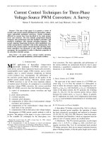
Current control techniques for three phase voltage source PWM converters a survey
Bạn đang xem bản rút gọn của tài liệu. Xem và tải ngay bản đầy đủ của tài liệu tại đây (298.96 KB, 13 trang )
IEEE TRANSACTIONS ON INDUSTRIAL ELECTRONICS, VOL. 45, NO. 5, OCTOBER 1998 691
Current Control Techniques for Three-Phase
Voltage-Source PWM Converters: A Survey
Marian P. Kazmierkowski,
Fellow, IEEE
, and Luigi Malesani,
Fellow, IEEE
Abstract— The aim of this paper is to present a review of
recently used current control techniques for three-phase voltage-
source pulsewidth modulated converters. Various techniques,
different in concept, have been described in two main groups:
linear and nonlinear. The first includes proportional integral
stationary and synchronous) and state feedback controllers, and
predictive techniques with constant switching frequency. The
second comprises bang-bang (hysteresis, delta modulation) con-
trollers and predictive controllers with on-line optimization. New
trends in the current control—neural networks and fuzzy-logic-
based controllers—are discussed, as well. Selected oscillograms
accompany the presentation in order to illustrate properties of
the described controller groups.
Index Terms— AC motor drives, current control, inverters,
power filters, pulsewidth modulation, switch-mode rectifiers.
I. I
NTRODUCTION
M
OST applications of three-phase voltage-source
pulsewidth modulated (VS-PWM) converters—ac
motor drives, active filters, high power factor ac/dc converters,
uninterruptible power supply (UPS) systems, and ac power
supplies—have a control structure comprising an internal
current feedback loop. Consequently, the performance of
the converter system largely depends on the quality of the
applied current control strategy. Therefore, current control
of PWM converters is one of the most important subjects
of modern power electronics. In comparison to conventional
open-loop voltage PWM converters, the current-controlled
PWM (CC-PWM) converters have the following advantages:
1) control of instantaneous current waveform and high
accuracy;
2) peak current protection;
3) overload rejection;
4) extremely good dynamics;
5) compensation of effects due to load parameter changes
(resistance and reactance);
6) compensation of the semiconductor voltage drop and
dead times of the converter;
7) compensation of the dc-link and ac-side voltage changes.
Development of PWM current control methods is still in
progress. The purpose of this paper is to give a short review
of the available CC techniques for the three-phase, two-
Manuscript received June 20, 1997; revised June 16, 1998. Abstract
published on the Internet July 3, 1998.
M. P. Kazmierkowski is with the Institute of Control and Industrial
Electronics, Warsaw University of Technology, 00-662 Warsaw, Poland.
L. Malesani is with the Department of Electrical Engineering, University
of Padova, 35131 Padova, Italy.
Publisher Item Identifier S 0278-0046(98)07015-4.
Fig. 1. Basic block diagram of CC-PWM converter.
level converters. The basic approaches and performance of
the various methods are summarized. However, due to space
limitations, a quantitative comparison of the methods under
discussion is not included.
II. B
ASIC
C
ONCEPTS
A. Basic Scheme of CC-PWM
The main task of the control scheme in a CC-PWM con-
verter (Fig. 1) is to force the currents in a three-phase ac
load to follow the reference signals. By comparing the com-
mand
and measured instantaneous
values of the phase currents, the CC generates the switching
states
for the converter power devices which
decrease the current errors
Hence, in general,
the CC implements two tasks: error compensation (decreasing
and modulation (determination of switching states
B. VS Converter as Power Amplifier
A three-phase VS bridge converter [Fig. 2(a)] is a discon-
tinuously operated power amplifier, the operation of which
has been extensively investigated and analyzed in literature
[1]–[5], [8], [9], [16], [18], [20]. However, some basic opera-
tion constraints and limitations, which are important from the
point of view of current control, are recalled below.
1) Modulation: The VS converter generates, at each output
phase
a voltage with a two-level rect-
angular waveform [Fig. 2(c)]. In conventional hard-switched
VS bridge converters, there are no mutual constraints between
phase switching instants, so that the pulse length can be varied
0278–0046/98$10.00 1998 IEEE
692 IEEE TRANSACTIONS ON INDUSTRIAL ELECTRONICS, VOL. 45, NO. 5, OCTOBER 1998
(a) (b)
(c) (d)
Fig. 2. Three-phase VS bridge converter. (a) Simplified main circuit topol-
ogy. (b) DC-link voltage for hard and soft switching [resonant dc-link
(RDCL) inverter]. (c) Time representation of the output ac voltages. (d) Vector
representation of the output ac voltages.
continuously (PWM). In some cases, however, commutation
mechanisms [RDCL inverters, Fig. 2(b)] or control systems
(e.g., delta modulation (DM), Fig. 9) allow commutations only
at fixed times. The modulation process controls the phase-
switching sequence according to a given command
so that
the phase voltage low-order harmonics result in a voltage
(average over the modulation period), the waveform of which
should follow
as closely as possible. Modulation generates
high-order voltage harmonics, located around the switching
frequency. If the latter is high enough, the two groups are
quite separated from each other.
2) Current Ripple and Switching Frequency: Modulation
also produces instantaneous deviations (ripple) of the current
from its average as an effect of the voltage harmonics.
Irrespective of the kind of modulation technique used, the
ripple amplitude depends on the duration of the modulation
period
(or on the modulation frequency the
supply voltage
the ac-side average voltage and
on the load parameters
With a purely inductive
load
the peak-to-peak ripple amplitude can be
expressed as
(a) (b)
(c) (d)
(e) (f)
Fig. 3. (a) and (b) Ripple and modulation frequency. (c), (e) PWM pulse
patterns and (d), (f) its vector representation.
Note that, if voltage varies [Fig. 3(a)], for a constant
modulation period
(and frequency the ripple amplitude
varies, too. However, if the ripple amplitude is kept constant,
the modulation frequency must vary, as shown in Fig. 3(b).
Usually, losses put a limitation on the average switching
frequency of each phase. In some cases, the control system, fil-
tering, or other needs may also require the switching frequency
to be constant.
3) Phase Interference Effect: If the neutral of the three-
phase load
and the converter midpoint (when available)
are not connected [Fig. 2(a)], phase currents depend only on
the voltage difference between phases. Therefore, a common
term can be added to the phase voltages, thus shifting their
mean value
without affecting load average currents
The current ripple, however, is changed by the shift. This
shift is often used to extend the maximum phase voltage which
can be produced by the converter (third harmonic PWM) and
to minimize the ripple, or to reduce the average switching
frequency (flat-top PWM) [4], [8], [19], [55].
KAZMIERKOWSKI AND MALESANI: CC TECHNIQUES FOR THREE-PHASE VS-PWM CONVERTERS 693
While phase voltages can be controlled independently, phase
currents are determined not only by their own phase voltage,
but also by those of other phases. Thus, a phase interference
occures. This phenomenon has to be taken into account in
designing CC.
4) Voltage Vector Sequence and Current Ripple: The con-
verter output voltage can be represented as a space vector [Fig.
2(d)]. This is particularly suitable when considering the phase
voltage effects on the load [4], [12], [14]. Vector sequences
with the same resultant give equal mean voltages
and,
therefore, equal average current
in an inductive load [Fig.
3(d) and (f)]. On the other hand, different vector paths produce
different current ripples. A sensible ripple reduction, mainly
at high modulation index, is obtained when phase pulses are
centered and symmetrical, with a choice of
corresponding
to Fig. 3(e). This condition results in a maximum zero-state
duration and, in vector representation [Fig. 3(f)], in an equal
length for states 0 and 7 [4], [8].
5) DC-Link Voltage Limit: A voltage reserve is required to
force an ac-side (load) current according to its command value.
For small amplitudes
of ac-side voltage, the dc-link voltage
is not critical. However, as is increased, a point is
reached where the converter passes to a six-step square-wave
operation and the CC is not capable of forcing the command
current. Therefore, the converter requires a sufficient supply
voltage reserve to force the ac line current in the entire
and
load range.
C. Basic Requirements and Performance Criteria
The accuracy of the CC can be evaluated with reference to
basic requirements, valid in general, and to specific require-
ments, typical of some applications. Basic requirements of a
CC are the following:
1) no phase and amplitude errors (ideal tracking) over a
wide output frequency range;
2) to provide high dynamic response of the system;
3) limited or constant switching frequency to guarantee safe
operation of converter semiconductor power devices;
4) low harmonic content;
5) good dc-link voltage utilization.
Note that some of the requirements, e.g., fast response
and low harmonic content, contradict each other. The spe-
cific requirements for the most important applications can be
summarized as follows.
1) VS PWM inverters
a) AC motor control: This requires a wide range of
output frequency, variable ac-side voltage (motor EMF),
high dynamic, decoupled
– control structure, operation
in PWM/square-wave transient region.
b) AC power supply/UPS: This requires a narrow range
of output frequency (UPS), reduced harmonic content (output
filter), and fault protection.
2) VS PWM AC/DC Converters and Active Filters: These
require constant ac-side (line power) frequency 50/60 Hz,
nearly constant amplitude and waveform of ac-side voltage,
poorly damped ac-side network, and variable dc-link voltage
(ac/dc converters and power filter).
TABLE I
P
ERFORMANCE
C
RITERIA
The evaluation of CC may be done according to perfor-
mance criteria which include static and dynamic performance.
Table I presents the static criteria in two groups:
1) those valid also for open-loop voltage PWM (see e.g.,
[1], [8], [9], [16]);
2) those specific for CC-PWM converters based on current
error definition (denoted by
The following parameters of the CC system dynamic re-
sponse can be considered: dead time, settling time, rise time,
time of the first maximum, and overshoot factor. The foregoing
features result both from the PWM process and from the
response of the control loop. For example, for deadtime, the
major contributions arise from signal processing (conversion
and calculation times) and may be appreciable, especially if
the control is of the digital type. On the other hand, rise time
is mainly affected by the ac-side inductances of the converter.
The optimization of the dynamic response usually requires a
compromise which depends on the specific needs. This may
also influence the choice of the CC technique according to the
application considered.
In general, the compromise is easier as the switching
frequency increases. Thus, with the speed improvement of
today’s switching components [e.g., insulated gate bipolar
transistors (IGBT’s)], the peculiar advantages of different
methods lose importance, and even the simplest one may be
adequate. Nevertheless, for some applications with specific
needs, like active filters, which require very fast response
or high power inverters where the commutations must be
minimized, the most suitable CC technique must be selected.
D. Presentation of CC Techniques
Existing CC techniques can be classified in different ways
[3], [8], [9], [11]–[13], [15], [27]. In this paper, the CC
techniques are presented in two main groups, linear and
nonlinear controllers.
III. L
INEAR
C
ONTROLLERS
The linear controllers operate with conventional voltage-
type PWM modulators [21]–[36]. In contrast to the nonlinear
controllers (see Section IV), linear controller schemes have
clearly separated current error compensation and voltage mod-
ulation parts. This concept allows us to exploit the advan-
694 IEEE TRANSACTIONS ON INDUSTRIAL ELECTRONICS, VOL. 45, NO. 5, OCTOBER 1998
(a) (b)
(c) (d)
Fig. 4. Linear current controllers. (a) Stationary PI. (b) Synchronous PI working in rotating coordinates with DC components. (c) synchronous PI working
in stationary coordinates with AC components. (d) State feedback controller.
tages of open-loop modulators (sinusoidal PWM, space-vector
modulator, and optimal PWM) which are constant switching
frequency, well-defined harmonic spectrum, optimum switch
pattern, and dc-link utilization. Also, full independent design
of the overall control structure, as well as open-loop testing
of the inverter and load, can be easily performed. In the linear
group, the following controllers are described: PI stationary
and synchronous, state feedback, and predictive with constant
switching frequency.
A. Stationary Controller PI
The stationary controller, also called the ramp comparison
current controller, uses three PI error compensators to produce
the voltage commands
for a three-phase sinu-
soidal PWM [Fig. 4(a)] [5]. In keeping with the principle of
sinusoidal PWM, comparison with the triangular carrier signal
generates control signals
for the inverter switches.
Although this controller is directly derived from the original
triangular suboscillation PWM [19], the behavior is quite
different, because the output current ripple is fed back and
influences the switching times. The integral part of the PI com-
pensator minimizes errors at low frequency, while proportional
gain and zero placement are related to the amount of ripple.
The maximum slope of the command voltage
should never exceed the triangle slope. Additional problems
may arise from multiple crossing of triangular boundaries.
As a consequence, the controller performance is satisfactory
only if the significant harmonics of current commands and
the load EMF are limited at a frequency well below the
carrier (less than 1/9 [4]). The main disadvantage of this
technique is an inherent tracking (amplitude and phase) error.
To achieve compensation, use of additional phase-locked loop
(PLL) circuits [24] or feedforward correction [29], [38] is also
made.
B. Synchronous Vector Controller (PI)
In many industrial applications, an ideally impressed current
is required, because even small phase or amplitude errors
cause incorrect system operation (e.g., vector-controlled ac
motors). In such cases, the control schemes based on the
space-vector approach are applied. Fig. 4(b) illustrates the
synchronous controller, which uses two PI compensators of
KAZMIERKOWSKI AND MALESANI: CC TECHNIQUES FOR THREE-PHASE VS-PWM CONVERTERS 695
current vector components defined in rotating synchronous
coordinates
– [5], [12], [14], [31], [32], [35]. Thanks to the
coordinate transformations,
and are dc components,
and PI compensators reduce the errors of the fundamental
component to zero.
Based on work in [34] (where it has been demonstrated that
is possible to perform current vector control in an arbitrary
coordinates), a synchronous controller working in the station-
ary coordinates
- with ac components has been presented
[33]. As shown in Fig. 4(c) by the dashed line, the inner
loop of the control system (consisting of two integrators and
multipliers) is a variable-frequency generator, which always
produces reference voltages
for the PWM modulator,
even when, in the steady state, the current error signals are
zero.
In general, thanks to the use of PWM modulators, the linear
controllers make a well-defined harmonic spectrum available,
but their dynamic properties are inferior to those of bang-bang
controllers.
C. State Feedback Controller
The conventional PI compensators in the current error com-
pensation part can be replaced by a state feedback controller
working in stationary [29] or synchronous rotating coordinates
[13], [25], [27], [28], [30]. The controller of Fig. 4(d) works
in synchronous rotating coordinates
– and is synthesized
on the basis of linear multivariable state feedback theory. A
feedback gain matrix
is derived by utilizing
the pole assignment technique to guarantee sufficient damping.
While with integral part
the static error can be reduced to
zero, the transient error may be unacceptably large. Therefore,
feedforward signals for the reference
and disturbance
inputs are added to the feedback control law.
Because the control algorithm guarantees the dynamically
correct compensation for the EMF voltage, the performance
of the state feedback controller is superior to conventional PI
controllers [27], [28].
D. Predictive and Deadbeat Controllers
This technique predicts at the beginning of each sampling
(modulation) period the current error vector on the basis of
the actual error and of the ac-side (load) parameters
, , .
The voltage vector to be generated by PWM during the next
modulation period is thus determinated, so as to minimize the
forecast error [60], [102], [105], [107]–[109].
Hybrid CC combining predictive and hysteresis techniques
have also been proposed [99].
1) Constant Switching Frequency Predictive Algorithm: In
this case, the predictive algorithm calculates the voltage vector
commands
once every sample period This will force
the current vector according to its command
[Fig. 5(a)].
The inverter voltage
and EMF voltage of the
load is assumed to be constant over the sample period
The
calculated voltage vector
is then implemented in the
PWM modulator algorithm, e.g., space vector [60], [86], [100],
[102] or sinusoidal modulator [107], [108]. Note that, while
the current ripple is variable, the inverter switching frequency
is fixed
The disadvantage of this algorithm is that it
does not guarantee the inverter peak current limit.
2) Deadbeat Controllers: When the choice of the voltage
vector is made in order to null the error at the end of the sample
period, the predictive controller is often called a deadbeat con-
troller [85], [94], [95], [97]. Among the additional information
given to the controller, nonavailable state variables (e.g., flux
and speed) can be included. Their determination can require
the use of observers or other control blocks, which often may
be shared with the control of the entire scheme, as in the case
of ac drives [83], [97].
IV. N
ONLINEAR
C
ONTROLLERS
The nonlinear CC group includes hysteresis, DM, and
on-line optimized controllers. To avoid confusion, current
controllers for the RDCL topology are presented separately.
Also, neural networks (NN’s) and fuzzy logic controllers
(FLC’s) belong to the class of nonlinear CC.
A. Hard-Switched Converters
1) Hysteresis Current Controllers: Hysteresis control
schemes are based on a nonlinear feedback loop with two-
level hysteresis comparators [Fig. 6(a)] [61]. The switching
signals
are produced directly when the error
exceeds an assigned tolerance band
[Fig. 6(b)].
a) Variable switching frequency controllers: Among the
main advantages of hysteresis CC are simplicity, outstanding
robustness, lack of tracking errors, independence of load
parameter changes, and extremely good dynamics limited only
by switching speed and load time constant. However, this class
of schemes, also known as freerunning hysteresis controllers
[16], has the following disadvantages.
1) The converter switching frequency depends largely on
the load parameters and varies with the ac voltage.
2) The operation is somewhat rough, due to the inher-
ent randomness caused by the limit cycle; therefore,
protection of the converter is difficult [56], [57].
It is characteristic of the hysteresis CC that the instantaneous
current is kept exact in a tolerance band, except for systems
without neutral leaders where the instantaneous error can
reach double the value of the hysteresis band [3], [54] (Fig.
7). This is due to the interaction in the system with three
independent controllers. The comparator state change in one
phase influences the voltage applied to the load in two other
phases (coupling). However, if all three current errors are
considered as space vectors [60], the interaction effect can
be compensated, and many variants of controllers known as
space-vector based can be created [41], [48], [50], [58], [63],
[68]. Moreover, if three-level comparators with a lookup table
are used, a considerable decrease in the inverter switching
frequency can be achieved [37], [48], [50], [58], [63]. This is
possible thanks to appropriate selection of zero-voltage vectors
[48] [Fig. 6(c)].
In the synchronous rotating
– coordinates, the error field
is rectangular, and the controller offers the opportunity of in-
dependent harmonic selection by choosing different hysteresis
values for the
and components [49], [62]. This can be used
696 IEEE TRANSACTIONS ON INDUSTRIAL ELECTRONICS, VOL. 45, NO. 5, OCTOBER 1998
(a) (b)
(c)
Fig. 5. Predictive current controllers. (a) Linear constant switching frequency controller. (b) Example of error area. (c) Minimum switching fre-
quency controller.
for torque-ripple minimization in vector-controlled ac motor
drives (the hysteresis band for the torque current component
is set narrower than that for the flux current component) [49],
[96].
Recent methods enable limit cycle suppression by introduc-
ing a suitable offset signal to either current references or the
hysteresis band [45], [65], [67].
b) Constant switching frequency controllers: A number
of proposals have been put forward to overcome variable
switching frequency. The tolerance band amplitude can be
varied, according to the ac-side voltage [39], [43], [47],
[53]–[55], [57], [59], [69], [103], or by means of a PLL
control (Fig. 8).
An approach which eliminates the interference, and its con-
sequences, is that of decoupling error signals by subtracting an
interference signal derived from the mean inverter voltage
(Fig. 8) [54]. Similar results are obtained in the case of “dis-
continuous switching” operation, where decoupling is more
easily obtained without estimating load impedance [55]. Once
decoupled, regular operation is obtained, and phase commuta-
tions may (but need not) be easily synchronized to a clock.
Although the constant switching frequency scheme is more
complex and the main advantage of the basic hysteresis con-
trol—namely, the simplicity—is lost, these solutions guarantee
very fast response together with limited tracking error. Thus,
constant frequency hysteresis controls are well suited for high-
performance high-speed applications.
2) Controllers with On-Line Optimization: This class of
controllers performs a real-time optimization algorithm and
requires complex on-line calculations, which usually can be
implemented only on microprocessors.
a) Minimum switching frequency predictive algorithm:
The concept of this algorithm [92] is based on space-vector
analysis of hysteresis controllers. The boundary delimiting the
current error area in the case of independent controllers with
equal tolerance band
in each of three phases makes a
regular symmetrical hexagon [Fig. 6(b)]. Suppose only one
hysteresis controller is used—the one acting on the current
error vector. In such a case, the boundary of the error area
(also called the switching or error curve) might have any form
[Fig. 5(b)]. The location of the error curve is determined by
the current command vector
When the current vector
reaches a point on the error curve, seven different trajectories
of the current are predicted, one for each of seven possible (six
active and zero) inverter output voltage vectors. Finally, based
on the optimization procedure, the voltage vector which mini-
mizes the mean inverter switching frequency is selected [Fig.
5(c)]. For fast transient states, the strategy which minimizes
the response time is applied.
b) Control with field orientation: The minimum fre-
quency predictive CC can be implemented in any rotating
or stationary coordinates. Like the three-level hysteresis
controller working in
– field-oriented coordinates [49],
a further switching frequency reduction can be achieved by
KAZMIERKOWSKI AND MALESANI: CC TECHNIQUES FOR THREE-PHASE VS-PWM CONVERTERS 697
(a) (b)
(c)
Fig. 6. Two-level hysteresis controller. (a) Block scheme. (b) Switching trajectory. (c) Number of inverter switchings
N
for a: three two-level hysteresis
comparators, b: three-level comparators and lookup table working in the stationary, and c: rotating coordinates.
Fig. 7. Hysteresis controller
(h =0:05)
. (a) Output currents. (b) Phase current error. (c) Vector current area. (d) Output vector current loci.
698 IEEE TRANSACTIONS ON INDUSTRIAL ELECTRONICS, VOL. 45, NO. 5, OCTOBER 1998
Fig. 8. Decoupled, constant average switching frequency hysteresis con-
troller [54].
the selection of a rectangular error curve with higher length
along rotor flux direction [96].
In practice, the time needed for the prediction and opti-
mization procedures limits the achieved switching frequency.
Therefore, in more recently developed algorithms, a reduced
set of voltage vectors consisting of the two active vectors
adjacent to the EMF vector and the zero voltage vector are
considered for optimization without loss of quality [8].
c) Trajectory tracking control: This approach, proposed
in [89] and [90], combines an off-line optimized PWM pattern
for steady-state operation with an on-line optimization to
compensate for the dynamic tracking errors of converter
currents. Such a strategy achieves very good stationary and
dynamic behavior even for low switching frequencies.
B. Soft-Switched RDCL Converters
In soft-switched RDCL three-phase converters with zero-
voltage switching (ZVS), the commutation process is restricted
to the discrete time instants
when the dc-link voltage pulses
are zero [Fig. 2(b)]. Therefore, special techniques called DM
or pulse density modulation (PDM) are used [70]–[82].
1) DM: The basic scheme, the DM current controller (DM-
CC) [74], [82], is shown in Fig. 9(a). It looks quite similar to
that of a hysteresis CC [Fig. 6(a)], but the operating principle
is quite different. In fact, only the error sign is detected by
the comparators, the outputs of which are sampled at a fixed
rate, so that the inverter status is kept constant during each
sampling interval. Thus, no PWM is performed; only basic
voltage vectors can be generated by the converter for a fixed
time. This mode of operation gives a discretization of the
inverter output voltage, unlike the continuous variation of
output voltages which is a particular feature of PWM.
One effect of the discretization is that, when synthesizing
periodic waveforms, a nonnegligible amount of subharmonics
is generated [74], [76], [77]. Thus, to obtain comparable
results, a DM should switch at a frequency about seven times
higher than a PWM modulator [76]. However, DM is very
simple and insensitive to the load parameters. When applied to
three-phase inverters with an insulated-neutral load, the mutual
phase interference and the increased degree of freedom in the
choice of voltage vector must be taken into account. Therefore,
instead of performing independent DM in each phase control,
output vectors are chosen depending not only on the error
vector, but also on the previous status, so that the zero vector
states become possible [73].
Due to the sample-and-hold (S&H) block applied after
the ideal comparator, the switching frequency is limited to
the sampling frequency
The amplitude of the current
harmonics is not constant, but is determined by the load
parameters, dc-link voltage, ac-side voltage, and sampling
frequency. If the sampling signal in the three-phase system
is shifted 120
in each S&H block [Fig. 9(b)], only one
of the inverter legs will change its state during the sample
period
This guarantees only adjacent and zero voltage
vector selection and, consequently, a better quality of current
waveform [lower rms, J (for definitions, see Table I)] at this
same sampling frequency
[Fig. 9(c)] [71].
It is noted that the DM-CC can also be applied in the
space-vector-based controllers working in either stationary or
rotating coordinates [75], [79], [81].
The main advantages of DM-CC are extremely simple and
tuning-free hardware implementation and good dynamics.
2) Optimal Discrete Modulation Algorithm: For the RDCL
converters, an optimal algorithm selects the voltage vector
which minimizes the rms current error for each resonant
pulse [80], [93], [106]. As shown in [106], this is equivalent
to selecting the nearest available voltage vector commands
So, instead of the PWM algorithm [Fig. 5(a)] only
the voltage vector selector is required [Fig. 10(a)]. However,
errors and subharmonics typical of the discrete modulation are
obtained. The typical waveforms for discrete DM and optimal
(minimum rms error) CC are shown in Fig. 11(a) and (b),
respectively.
C. NN’s and FL-Based Controllers
Recently, new emerging technologies such as NN’s and FL
methods have been applied to PWM current control.
1) NN’s Controllers: The main advantages of NN are par-
allel processing, learning ability, robustness, and general-
ization. They can be effectively used for CC [110]–[112],
[115]–[117], [120].
A simple example, which allows for the elimination of the
on-line calculations needed to implement the optimal discrete
CC of Fig. 10(a), is shown in Fig. 10(b) [117]. The three layers
of the feedforward NN with sigmoidal nonlinearity—before
using as a controller—were trained using a back propagation
algorithm with randomly selected data from the output pattern
of the optimal controller of Fig. 10(a). After training, the
performance of the three-layer (architecture: 5-10-10-3) NN-
based controllers differs only slightly from that of the optimal
regulator [Fig. 11(c)]. Thus, the NN-based controller can
be used to regulate PWM converter output current without
a need for the on-line calculation required for an optimal
controller.
With this approach, however, no further training of the
NN is possible during controller operation. Therefore, the
KAZMIERKOWSKI AND MALESANI: CC TECHNIQUES FOR THREE-PHASE VS-PWM CONVERTERS 699
(a) (b)
(c)
Fig. 9. DM current controller. (a) Basic scheme. (b) Sampling techniques. (c) Quality factors.
(a)
(b)
Fig. 10. (a) Optimal (mode) discrete modulation controller for RDCL
converter. (b) NN discrete modulation controller for RDCL converter.
performance of such an off-line trained NN controller depends
upon the amount and quality of training data used and is
Fig. 11. Current control in RDCL based on discrete modulation. From
the top: I—line-to-line voltage
u
; II—current vector components
i
;i
;
III—current error
(
2
+
2
)
1=2
; IV—rms and J of current error
(t):
also sensitive to parameter variations. For systems where
parameters variations have to be compensated, an on-line
trained NN controller can be applied [111], [112], [116]. In
[112], an NN induction motor CC with parameter identification
700 IEEE TRANSACTIONS ON INDUSTRIAL ELECTRONICS, VOL. 45, NO. 5, OCTOBER 1998
(a)
(b) (c)
(d) (e)
Fig. 12. (a) Block scheme of FL controller, (b) control surface of con-
ventional PI controller, (c) control surface of FL controller; comparison of
current-tracking performance with PI and FL controller: (d) current waveform,
and (e) current vector loci.
was proposed. To achieve very fast on-line training (8 s for
one training cycle) a new algorithm called random weight
change (RWC) is applied. This algorithm allows us to identify
and control the motor currents within a few milliseconds.
2) FL-CC’s: In basic applications, the FLC is used as a
substitute for the conventional PI compensator [114], [118].
The block scheme of the FL-CC is similar to the system of
Fig. 4(a), where, instead of PI, FL self-tuned PI controllers
are used. The basic block scheme of an FL-tuned discrete PI
controller, including the fuzzy inference mechanism, is shown
in Fig. 12(a). The current error
and its derivative are
the FL controller input crisp values. The reference voltage for
the PWM modulator are the FL-CC crisp output commands
When an FL controller is used as a current controller, the
tracking error and transient overshoots of PWM current control
can be considerably reduced [Fig. 12(d) and (e)]. This is
because—in contrast to the conventional PI compensator—the
control surface of the FL controller can be shaped to define
appropriate sensitivity for each operating point [Fig. 12(b) and
(c)]. The FL-tuned PI controller can easily be implemented
as an off-line precalculated three-dimensional lookup table
consisting of the control surface [114]. However, the properties
of the FL controller are very sensitive to any change of fuzzy
sets shapes and overlapping. Therefore, the design procedure
and resulting performance depend strongly on the knowledge
and expertise of the designer.
V. C
ONCLUSIONS
CC techniques for VS converters can be divided into two
groups: 1) linear, i.e, stationary, synchronous, and predictive
deadbeat controllers and 2) nonlinear, i.e., hysteresis, DM, and
on-line optimized controllers. The basic principles and the lat-
est developments of these techniques have been systematically
described in this paper. The advantages and limitations have
been briefly examined, and the application field where each
technique is particularly suited has been indicated.
Recently, the research trend favors fully digital control.
Thus, the methods which allow digital implementation are
preferred, even with some sacrifice in accuracy and dynamic
performance. In particular, for low-performance applications
with large diffusion (e.g., pumps, blowers and fans, and
retrofit applications), digitally implemented PI regulators are
adequate. Use of linear predictive and on-line optimized CC
is growing fast in medium- and high-performance systems,
especially for traction and high power units. Hysteresis CC,
in their improved versions, are well suited to fast, accurate
conversion systems (e.g., power filters and UPS’s).
It is possible that NN’s and FL-based CC techniques can
offer a new interesting perspective for future research. At
present, however, they represent only an alternative solution
to existing CC methods, and their specific applications areas
cannot be clearly defined.
R
EFERENCES
[1] B. K. Bose, Power Electronics and Variable Frequency Drives. Piscat-
away, NJ: IEEE Press, 1996.
[2] B. K. Bose, Power Electronics and Electrical AC Drives. Englewood
Cliffs, NJ: Prentice-Hall, 1986.
[3] D. M. Brod and D. W. Novotny, “Current control of VSI-PWM in-
verters,” IEEE Trans. Ind. Applicat., vol. IA-21, pp. 562–570, July/Aug.
1985.
[4] H. W. van der Broeck, H. Ch. Skudelny, and G. Stanke, “Analysis and
realization of a pulse width modulator based on voltage space vectors,”
IEEE Trans. Ind. Applicat., vol. 24, pp. 142–150, Jan./Feb. 1988.
[5] H. B
¨
uhler, Einf¨uhrung in die Theorie geregelter Drehstrom-Antriebe, Bd.
1, Bd. 2. Basel, Switzerland: Birkhauser, 1977.
[6] H. Ertl, J. W. Kolar, and F. C. Zach, “Analysis of different current
control concepts for forced commutated rectifier (FCR),” in Proc. PCI
Conf., 1986, pp. 195–217.
[7] J. Holtz, W. Lotzkat, and A. M. Khambadadkone, “On continous control
of PWM inverters in the overmodulation range including the six-step
mode,” IEEE Trans. Power Electron., vol. 8, pp. 546–553, Oct. 1993.
[8] J. Holtz, “Pulsewidth modulation for electronic power conversion,”
Proc. IEEE, vol. 82, pp. 1194–1214, Aug. 1994.
[9] F. Jenni, D. W
¨
ust, Steuerverfahren f¨ur selbstgef¨uhrte Stromrichter.
Stuttgart, Germany: B. G. Teubner, 1995.
[10] D. Jouve, J. P. Rognon, and D. Roye, “Effective current and speed
controllers for permanent magnet machines: A survey,” in Proc. IEEE
APEC’90, 1990, pp. 384–393.
[11] M. P. Kazmierkowski and M. A. Dzieniakowski, “Review of current reg-
ulation methods for VS-PWM inverters,” in Conf. Rec. IEEE IECON’94,
1994, pp. 567–575.
[12] M. P. Kazmierkowski and H. Tunia, Automatic Control of Converter-Fed
Drives. Amsterdam, The Netherlands: Elsevier, 1994.
[13] D. C. Lee, S. K. Sul, and M. H. Park, “Comparison of AC current
regulators for IGBT inverter,” in Conf. Rec. PCC’93, Yokohama, Japan,
1993, pp. 206–212.
[14] W. Leonhard, Control of Electrical Drives, 2nd ed. Berlin, Germany:
Springer-Verlag, 1996.
KAZMIERKOWSKI AND MALESANI: CC TECHNIQUES FOR THREE-PHASE VS-PWM CONVERTERS 701
[15] L. Malesani and P. Tomasin, “PWM current control techniques of
voltage source converters—A survey,” in Conf. Rec. IEEE IECON’93,
Maui, HI, 1993, pp. 670–675.
[16] J. D. M. Murphy and F. G. Turnbull, Control Power Electronics of AC
Motors. New York: Pergamon, 1988.
[17] D. W. Novotny and T. A. Lipo, Vector Control and Dynamics of AC
Drives. Oxford, U.K.: Clarendon, 1996.
[18] S. Ogasawara, H. Akagi, and A. Nabae, “A novel PWM scheme of
voltage inverter based on space vector theory,” in Proc. EPE Conf.,
1989, pp. 3.1197–1202.
[19] A. Sch
¨
onung and H. Stemmler, “Static frequency changers with subhar-
monic control in conjunction with reversible variable speed a.c. drives,”
Brown Boweri Rev., pp. 555–577, Aug/Sept. 1964.
[20] A. M. Trzynadlowski, “An overview of modern PWM techniques for
three-phase voltage controlled, voltage-source inverters,” in Conf. Rec.
IEEE ISIE’96, Warsaw, Poland, 1996, pp. 25–39.
[21] Y. Baudon, D. Youve, and J. P. Ferrieux, “Current control of permanent
magnet synchronous machines. Experimental and simulation study.”
IEEE Trans. Power Electron., vol. 7, no. 3, pp. 560–567, July 1992.
[22] J. H. Choi and B. J. Kim, “Improved digital control scheme of three
phase UPS inverter using double control strategy,” in Proc. APEC’97,
1997, pp. 820–824.
[23] J. W. Choi and S. K. Sul, “New current control concept—Minimum
time current control in 3-phase PWM converter,” in Conf. Rec. IEEE
PESC’95, 1995, pp. 332–338.
[24] P. Enjeti, P. D. Ziogas, J. F. Lindsay, and M. H. Rashid, “A novel current
controlled PWM inverter for variable speed AC drives,” in Conf. Rec.
IEEE-IAS Annu. Meeting, Denver, CO, 1986, pp. 235–243.
[25] P. Feller, “Speed control of an ac motor by state variables feedback with
decoupling,” in Proc. IFAC Control in Power Electronics and Electrical
Drives, Lausanne, Switzerland, 1983, pp. 87–93.
[26] J. Holtz and B. Bayer, “Optimal pulsewidth modulation for AC servos
and low-cost industrial drives,” in Conf. Rec. IEEE-IAS Annu. Meeting,
Houston, TX, 1992, pp. 1010–1017.
[27] D. C. Lee, S. K. Sul, and M. H. Park, “High performance current
regulator for a field-oriented controlled induction motor drive,” IEEE
Trans. Ind. Applicat., vol. 30, pp. 1247–1253, Sept./Oct. 1994.
[28]
, “Novel current regulation for a field-oriented controlled induc-
tion motor drive,” in Proc. ISPE’92, 1992, pp. 135–141.
[29] R. D. Lorenz and D. B. Lawson, “Performance of feedforward current
regulators for field oriented induction machine controllers,” IEEE Trans.
Ind. Applicat., vol. IA-23, pp. 597–602, July/Aug. 1987.
[30] J. Moerschel, “Signal processor based field oriented Vector Control for
an induction motor drive,” in Proc. EPE Conf., Florence, Italy, 1991,
pp. 2.145–2.150.
[31] L. Norum, W. Sulkowski, and L. A. Aga, “Compact realization of
PWM-VSI current controller for PMSM drive application using low
cost standard microcontroller,” in Conf. Rec. IEEE PESC’92, Toledo,
Spain, 1992, pp. 680–685.
[32] C. T. Rim, N. S. Choi, G. C. Cho, and G. H. Cho, “A complete DC
and AC analiysis of three-phase controlled-current PWM rectifer using
circuit D-Q transformation,” IEEE Trans. Power Electron., vol. 9, pp.
390–396, July 1994.
[33] T. M. Rowan and R. J. Kerkman, “A new synchronous current regulator
and an analysis of current regulated PWM inverters,” IEEE Trans. Ind.
Applicat., vol. IA-22, pp. 678–690, July/Aug. 1986.
[34] D. Schauder and R. Caddy, “Current control of voltage-source inverters
for fast four-quadrant drive performance,” IEEE Trans. Ind. Applicat.,
vol. IA-18, pp. 163–171, Jan./Feb. 1982.
[35] R. B. Sepe and J. H. Lang, “Inverter nonlinearities and discrete-time
vector current control,” IEEE Trans. Ind. Applicat., vol. 30, pp. 62–70,
Jan./Feb. 1994.
[36] N. R. Zargari, G. Joos, “Performance investigation of a current-
controlled voltage-regulated PWM rectifer in rotating and stationary
frames,” in Proc. IEEE IECON’93, 1993, pp. 1193–1198.
[37] A. Ackva, H. Reinold, and R. Olesinski, “A simple and self-adapting
high-performance current control scheme for three-phase voltage source
inverters,” in Conf. Rec. IEEE PESC’92, Toledo, Spain, 1992, pp.
435–442.
[38] C. Andrieux and M. Lajoie-Mazenc, “Analysis of different current
control systems for inverter-fed synchronous machine,” in Proc. EPE
Conf., Brussels, Belgium, 1985, pp. 2.159–2.165.
[39] B. K. Bose, “An adaptive hysteresis-band current control technique of
a voltage-fed PWM inverted for machine drive system,” IEEE Trans.
Ind. Electron., vol. 37, pp. 402–408, Oct. 1990.
[40] M. Carpita and M. Marchesoni, “Experimental study of a power
conditioning system using sliding mode control,” IEEE Trans. Power
Electron., vol. 11, pp. 731–742, Sept. 1996.
[41] T. Y. Chang and T.C. Pan, “A practical vector control algorithm for
-based induction motor drives using a new space vector controller,”
IEEE Trans. Ind. Electron., vol. 41, pp. 97–103, Feb. 1994.
[42] C. Chiarelli, L. Malesani, S. Pirondini, and P. Tomasin, “Single-
phase, three-level, constant frequency current hysteresis control for UPS
applications,” in Proc. EPE Conf., Brighton, U.K., 1993, pp. 180–
185.
[43] T. W. Chun and M. K. Choi, “Development of adaptive hysteresis
band current control strategy of PWM inverter with constant switching
frequency,” in Proc. IEEE APEC’96, San Jose, CA, 1996, pp. 194–199.
[44] E. Gaio, R. Piovan, and L. Malesani, “Comparative analysis of hysteresis
modulation methods for VSI current control,” in Proc. IEE Machines
and Drives Conf., London, U.K., 1988, pp. 336–339.
[45] V. J. Gosbell and P. M. Dalton, “Current control of induction motors at
low speed,” IEEE Trans. Ind. Applicat., vol. 28, pp. 482–489, Mar./Apr.
1992.
[46] S. L. Jung and Y. Y. Tzou, “Sliding mode control of a closed-loop
regulated PWM inverter under large load variations,” in Conf. Rec. IEEE
PESC’93, 1993, pp. 616–622.
[47] A. Kawamura and R. G. Hoft, “Instantaneous feedback controlled PWM
inverters with adaptive hysteresis,” IEEE Trans. Ind. Applicat., vol.
IA-20, pp. 769–775, July/Aug. 1984.
[48] M. P. Kazmierkowski, M. A. Dzieniakowski, and W. Sulkowski, “Novel
space vector based current controllers for PWM-inverters,” IEEE Trans.
Power Electron., vol. 6, pp. 158–166, Jan. 1991.
[49] M. P. Kazmierkowski and W. Sulkowski, “A novel vector control
scheme for transistor PWM inverted-fed induction motor drive,” IEEE
Trans. Ind. Electron. , vol. 38, pp. 41–47, Feb. 1991.
[50] B H. Kwon, T W. Kim, and J H. Youn, “A novel SVM-based hys-
teresis current controller,” IEEE Trans. Power Electron., vol. 13, pp.
297–307, Mar. 1998.
[51] M. Lajoie-Mazenc, C. Villanueva, and J. Hector, “Study and implemen-
tation of hysteresis control inverter on a permanent magnet synchronous
machine,” in Conf. Rec. IEEE-IAS Annu. Meeting, Chicago, IL, 1984,
pp. 426–431.
[52] L. Malesani, P. Mattiavelli, and P. Tomasini, “High-performance histere-
sis modulation technique for active filters,” in Proc. IEEE APEC’96,
1996, pp. 939–946.
[53] L. Malesani, L. Rossetto, L. Sonaglioni, P. Tomasin, and A. Zuccato,
“Digital, adaptive hysteresis current control with clocked commutations
and wide operating range,” IEEE Trans. Ind. Applicat., vol. 32, pp.
1115–1121, Mar./Apr. 1996.
[54] L. Malesani and P. Tenti, “A novel hysteresis control method for current
controlled VSI PWM inverters with constant modulation frequency,”
IEEE Trans. Ind. Applicat., vol. 26, pp. 88–92, Jan./Feb. 1990.
[55] L. Malesani, P. Tenti, E. Gaio, and R. Piovan, “Improved current control
technique of VSI PWM inverters with constant Modulation frequency
and extended voltage range,” IEEE Trans. Ind. Applicat., vol. 27, pp.
365–369, Mar./Apr. 1991.
[56] W. McMurray, “Modulation of the chopping frequency in dc choppers
and inverters having current hysteresis controllers,” IEEE Trans. Ind.
Applicat., vol. IA-20, pp. 763–768, July/Aug. 1984.
[57] I. Nagy, “Novel adaptive tolerance band based PWM for field oriented
control of induction machines,” IEEE Trans. Ind. Electron., vol. 41, pp.
406–417, Aug. 1994.
[58] C. T. Pan and T. Y. Chang, “An improved hysteresis current controller
for reducing switching frequency,” IEEE Trans. Power Electron., vol.
9, pp. 97–104, Jan. 1994.
[59] E. Perssen, N. Mohan, and B. Ben Banerjee, “Adaptive tolerance-
band control of standby power supply provides load-current harmonic
neutralization,” in Conf. Rec. IEEE PESC’92, Toledo, Spain, 1992, pp.
320–326.
[60] G. Pfaff, A. Weschta, and A. Wick, “Design and experimental results
of a brushless ac servo drive,” IEEE Trans. Ind. Applicat., vol. IA-22,
pp. 814–821, July/Aug. 1984.
[61] A. B. Plunkett,” A current controlled PWM transistor inverted drive,”
in Conf. Rec. IEEE-IAS Annu. Meeting, 1979, pp. 785–792.
[62] J. Rodriguez and G. K¨astner, “Nonlinear current control of an inverted-
fed induction machine,” ETZ Arch., vol. 9, no. 8, pp. 245–250, 1987.
[63] C. Rossi and A. Tonielli, “Robust current controller for three-phase
inverter using finite-state automation,” IEEE Trans. Ind. Electron., vol.
42, Apr. 1995.
[64] N. Sabanovic-Behlilovic, T. Ninomiya, A. Sabanovic, and B. Perunicic,
“Control of three-phase switching converters, a sliding mode approach,”
in Conf. Rec. IEEE PESC’93, 1993, pp. 630–635.
[65] S. Salama and S. Lennon, “Overshoot and limit cycle free current control
method for PWM inverter,” in Proc. EPE Conf., Florence, Italy, 1991,
pp. 3.247–3.251.
702 IEEE TRANSACTIONS ON INDUSTRIAL ELECTRONICS, VOL. 45, NO. 5, OCTOBER 1998
[66] A. Tripathi and P. C. Sen, “Comparative analysis of fixed and sinusoidal
band hysteresis current controllers for voltage source inverters,” IEEE
Trans. Ind. Electron., vol. 39, pp. 63–73, Feb. 1992.
[67] K. Tungpimolrut, M. Matsui, and T. Fukao, “A simple limit cycle
suppression scheme for hysteresis current controlled PWM-VSI with
consideration of switching delay time,” in Conf. Rec. IEEE-IAS Annu.
Meeting, Houston, TX, 1992, pp. 1034–1041.
[68] D. W
¨
ust and F. Jenni, “Space vector based current control schemes for
voltage source inverters,” in Conf. Rec. IEEE PESC’93, Seattle, WA,
1993, pp. 986–992.
[69] Q. Yao and D. G. Holmes, “A simple, novel method for variable-
hysteresis-band current control of a three phase inverter with constant
switching frequency,” in Conf. Rec. IEEE-IAS Annu. Meeting, 1993, pp.
1122–1129.
[70] D. M. Divan, G. Venkataramanan, L. Malesani, and V. Toigo, “Control
strategies for synchronized resonant link inverters,” in Conf. Rec.
IPEC’90, Tokyo, Japan, 1990, pp. 338–345.
[71] M. A. Dzieniakowski and M. P. Kazmierkowski, “Microprocessor-based
novel current regulator for VSI-PWM inverters,” in Conf. Rec. IEEE
PESC’92, Toledo, Spain, 1992, pp. 459–464.
[72] P. Freere, D. Atkinson, and P. Pillay, “Delta current control for vector
controlled permanent magnet synchronous motors,” in Conf. Rec. IEEE-
IAS Annu. Meeting, Houston, TX, 1992, pp. 550–557.
[73] T. G. Habetler and D. M. Divan, “Performance characterization of a
new discrete pulse modulated current regulator,” in Conf. Rec. IEEE-IAS
Annu. Meeting, Pittsburgh, PA, 1988, pp. 395–405.
[74] M. Kheraluwala and D. M. Divan, “Delta modulation strategies for res-
onant link inverters,” in Conf. Rec. IEEE PESC’87, 1987, pp. 271–278.
[75] R. D. Lorenz and D. M. Divan, “Dynamic analysis and experimental
evaluation of delta modulators for field oriented ac machine current
regulators,” in Conf. Rec. IEEE-IAS Annu. Meeting, Atlanta, GA, 1987,
pp. 196–201.
[76] A. Mertens, “Performance analysis of three phase inverters controlled
by synchronous delta-modulation systems,” IEEE Trans. Ind. Applicat.,
vol. 30, pp. 1016–1027, July/Aug. 1994.
[77] A. Mertens and H.Ch. Skudelny, “Calculations on the spectral perfor-
mance of sigma delta modulators,” in Conf. Rec. IEEE PESC’91, 1991,
pp. 357–365.
[78] M. A. Rahman, J. E. Quaice, and M. A. Chowdry, “ Performance
analysis of delta modulation PWM inverters,” IEEE Trans. Power
Electron., vol. 2, pp. 227–233, May 1987.
[79] G. Venkataramanan and D. M. Divan, “Improved performance voltage
and current regulators using discrete pulse modulation,” in Conf. Rec.
IEEE PESC’92, Toledo, Spain, 1992, pp. 601–606.
[80] G. Venkataramanan, D. M. Divan, and T. M. Jahns, “Discrete pulse
modulation stategies for high frequency inverter systems,” in Conf. Rec.
IEEE PESC’89, 1989, pp. 1013–1020.
[81] X. Xu and D. W. Novotny, “Bus utilization of discrete CRPWM
inverters for field oriented drives,” in Conf. Rec. IEEE-IAS Annu.
Mteeting, 1988, pp. 362–367.
[82] D. Ziogas, “The delta modulation technique in static PWM inverters,”
IEEE Trans. Ind. Applicat., vol. IA-17, pp. 199–204, Mar./Apr. 1982.
[83] L. Ben-Brahim and A. Kawamura, “Digital current regulation of field-
oriented controlled induction motor based on predictive flux observer,”
in Conf. Rec. IEEE-IAS Annu. Meeting, 1990, pp. 607–612.
[84] L. J. Borle and C. V. Nayar, “Zero avarage current error controlled
power flow for AC-DC power converters,” IEEE Trans. Power Electron.,
vol. 10, pp. 725–732, Nov. 1995.
[85] K. P. Gokhale, A. Kawamura, and R. G. Hoft, “Dead beat micropro-
cessor control of PWM inverter for sinusoidal output waveform syn-
thesis,” IEEE Trans. Ind. Applicat., vol. IA-23, pp. 901–909, Sept./Oct.
1987.
[86] T. G. Habetler, “A space vector based rectifier regulator for AC/DC/AC
converters,” in Proc. EPE Conf., Florence, Italy, 1991, pp. 2.101–2.107.
[87] W. Hofmann, “Practical design of the current error trajectory control
for PWM AC-drives,” in Proc. IEEE APEC’96, 1996, pp. 782–787.
[88] D. G. Holmes and D. A. Martin, “Implementation of a direct digital
predictive current controller for single and three phase voltage source
inverters,” in Conf. Rec. IEEE-IAS Annu. Meeting, San Diego, CA, 1996,
pp. 906–913.
[89] J. Holtz and B. Bayer, “Fast current trajectory tracking control based
on synchronous optimal pulsewidth modulation,” IEEE Trans. Ind.
Applicat., vol. 31, pp. 1110–1120, Sept./Oct. 1995.
[90]
, “The trajectory tracking approach—A new method for minimum
distortion PWM in dynamic high power drives,” IEEE Trans. Ind.
Applicat., vol. 30, pp. 1048–1057, July/Aug. 1994.
[91] J. Holtz and E. Bube, “Field oriented asynchronous pulsewidth modula-
tion for high performance ac machine drives operating at low switching
frequency,” IEEE Trans. Ind. Applicat., vol. 27, pp. 574–581, May/June
1991.
[92] J. Holtz and S. Stadtfeld, “A predictive controller for the stator current
vector of ac machines fed from a switched voltage source,” in Proc.
IPEC, Tokyo, Japan, 1983, pp. 1665–1675.
[93] M. Kassas, M. Wells, and M. Fashoro, “Design and simulation of current
regulators for induction motors using the error magnitude voltage vector
correction (EMVVC)” in Conf. Rec. IEEE-IAS Annu. Meeting, 1992, pp.
132–138.
[94] T. Kawabata, T. Miyashita, and Y. Yamamoto, “Dead beat control of
three phase PWM inverter,” IEEE Trans. Power Electron., vol. 5, pp.
21–28, Jan. 1990.
[95] A. Kawamura, T. Haneyoshi, and R. G. Hoft, “Deadbeat controlled
PWM inverter with parameter estimation using only voltage sensor,” in
Conf. Rec. IEEE PESC’86, 1986, pp. 576–583.
[96] A. Khambadkone and J. Holtz, “Low switching frequency high-power
inverter drive based on field-oriented pulse width modulation,” in Proc.
EPE Conf., 1991, pp. 4.672–4.677.
[97] J. W. Kolar, H. Ertl, and F. C. Zach, “Analysis of on- and off-line
optimized predictive current controllers for PWM converter system,”
IEEE Trans. Power Electron., vol. 6, pp. 454–462, May 1991.
[98] O. Kukrer, “Discrete-time current control of voltage-fed three-phase
PWM inverters,” IEEE Trans. Power Electron., vol. 11, pp. 260–269,
Mar. 1996.
[99] H. Le-Huy and L. Dessaint, “An adaptive current control scheme for
PWM synchronous motor drives: Analysis and simulation,” IEEE Trans.
Power Electron., vol. 4, pp. 486–495, Oct. 1989.
[100] H. Le-Huy, K. Slimani, and P. Viarouge, “Analysis and implementation
of a real-time predictive current controller for permanent-magnet syn-
chronous servo drives,” IEEE Trans. Ind. Electron., vol. 41, pp. 110–117,
Feb. 1994.
[101] I. Miki, O. Nakao, and S. Nishiyma, “A new simplified current control
method for field oriented induction motor drives,” in Conf. Rec. IEEE-
IAS Annu. Meeting, 1989, pp. 390–395.
[102] H. R. Mayer and G. Pfaff, “Direct control of induction motor cur-
rents—Design and experimental results,” in Proc. EPE Conf., Brussels,
Belgium, 1985, pp. 3.7–3.12.
[103] A. Nabae, S. Ogasawara, and H. Akagi, “A novel control scheme of
current-controlled PWM inverters,” IEEE Trans. Ind. Applicat., vol.
IA-22, pp. 697–701, July/Aug. 1986.
[104] D. S. Oh, K. Y. Cho, and M. J. Youn, “A discretized current control tech-
nique with delayed voltage feedback for a voltage-fed PWM inverter,”
IEEE Trans. Power Electron., vol. 7, pp. 364–373, Apr. 1992.
[105] G. Pfaff and A. Wick, “Direct current control of ac drives with pulsed
frequency converters,” Process Automat., vol. 2, no. 2, pp. 83–88, Feb.
1983.
[106] S. K. Sul, B. H. Kwon, J. K. Kang, K. J. Lim, and M. H. Park, “Design
of an optimal discrete current regulator,” in Conf. Rec. IEEE-IAS Annu.
Meeting, 1989, pp. 348–354.
[107] R. Wu, S. B. Dewan, and G. R. Slemon, “A PWM ac-dc converter
with fixed switching frequency,” IEEE Trans. Ind. Applicat., vol. 26,
pp. 880–885, Sept./Oct. 1990.
[108]
, “Analysis of a PWM ac to dc voltage source converter under
the predicted current control with a fixed switching frequency,” IEEE
Trans. Ind. Applicat., vol. 27, pp. 756–764, July/Aug. 1991.
[109] L. Zhang and F. Hardan, “Vector controlled VSI-fed AC drive using
a predictive space-vector current regulation scheme,” in Proc. IEEE
IECON’94, 1994, pp. 61–66.
[110] Buhl and R. D. Lorenz, “Design and implementation of neural networks
for digital current regulation of inverter drives,” in Conf. Rec. IEEE-IAS
Annu. Meeting, 1991, pp. 415–421.
[111] B. Burton, R. G. Harley, G. Diana, and J. R. Rodgerson, “ Implemen-
tation of a neural network to adaptively identify and control VSI fed
induction motor stator currents,” in Conf. Rec. IEEE-IAS Annu. Meeting,
Denver, CO, 1994, pp. 1733–1740.
[112] B. Burton, F. Karman, R. G. Harley, T. G. Habetler, M. A. Brooke, and
R. Poddar, “Identification and control of induction motor stator currents
using fast on-line random training of a neural network,” IEEE Trans.
Ind. Applicat., vol. 33, pp. 697–704, May/June 1997.
[113] M. A. Dzieniakowski and P. Z. Grabowski, “Fuzzy logic controller
with state recognation for three phase PWM-VSI,” in Conf. Rec. IEEE
ISIE’96, Warsaw, Poland, 1996, pp. 438–443.
[114] M. A. Dzieniakowski and M. P. Kazmierkowski, “Self-tuned fuzzy PI
current controller for PWM-VSI,” in Proc. EPE Conf., Seville, Spain,
1995, pp. 1.308–1.313.
[115] F. Harashima, Y. Demizu, S. Kondo, and H. Hashimoto, “Application
of neural networks to power converter control,” in Conf. Rec. IEEE-IAS
Annu. Meeting, San Diego, CA, 1989, pp. 1087–1091.
KAZMIERKOWSKI AND MALESANI: CC TECHNIQUES FOR THREE-PHASE VS-PWM CONVERTERS 703
[116] Y. Ito, T. Furuhashi, S. Okuma, and Y. Uchikawa, “A digital current
controller for a PWM inverter using a neural network and its stability,”
in Conf. Rec. IEEE PESC’90, San Antonio, TX, 1990, pp. 219–224.
[117] M. P. Kazmierkowski, D. L. Sobczuk, and M. A. Dzieniakowski,
“Neural network current control of VS-PWM inverters,” in Proc. EPE
Conf., Seville, Spain, 1995, pp. 1.415–1.420.
[118] S. S. Min, K. C. Lee, J. W. Song, and K. B. Cho, “A fuzzy current
controller for field-oriented controlled induction machine by fuzzy rule,”
in Conf. Rec. IEEE PESC’92, Toledo, Spain, 1992, pp. 265–270.
[119] S. Saetieo and D. A. Torrey, “Fuzzy logic control of a space vector
PWM current regulator for three phase power converters,” in Proc. IEEE
APEC’97, 1997, pp. 879–885.
[120] D. R. Seidl, D. A. Kaiser, and R. D. Lorenz, “One-step optimal space
vector PWM current regulation using a neural network,” in Conf. Rec.
IEEE-IAS Annu. Meeting, 1994, pp. 867–874.
[121] Y. Y. Tzou, “Fuzzy-tuning current-vector control of a 3-phase PWM
inverter,” in Conf. Rec. IEEE PESC’95, 1995, pp. 326–331.
Marian P. Kazmierkowski (M’89–SM’91–FM’98), for a photograph and
biography, see this issue, p. 690.
Luigi Malesani(M’63–SM’93–FM’94), for a photograph and biography, see
this issue, p. 690.