project report anti theft alarm sensor for home
Bạn đang xem bản rút gọn của tài liệu. Xem và tải ngay bản đầy đủ của tài liệu tại đây (630.98 KB, 26 trang )
<span class="text_page_counter">Trang 1</span><div class="page_container" data-page="1">
HANOI UNIVERSITY OF SCIENCE AND TECHNOLOGYSCHOOL OF ELECTRONICS AND TELECOMMUNICATIONS
Name of instructor: Assoc. Prof. Truong Thu Huong
Hanoi, 3-2023
</div><span class="text_page_counter">Trang 4</span><div class="page_container" data-page="4">In the age of the present information explosion, the applicability and the potential development of the advertising information are very big, the application of the new techniques is very necessary in this field.
We really appreciate Prof. Truong Thu Huong help with our project, and he created favorable conditions for our team to complete brilliantly this project.
Although we made every effort, our ability is limited. Moreover, this project is a new field for our team, so we should not avoid design errors in content and the method of presentation. Our team is looking forward to Prof. Truong Thu Huong's guidance and your additional suggestion to improve this project.
We would like to say thanks to everybody who helps us on this project!
</div><span class="text_page_counter">Trang 5</span><div class="page_container" data-page="5">Burglaries happen every day and become the most-mentioned property crime worry in every corner of Viet Nam. So, the demand for a system which can support owners to protect theirs home is indispensable. The goal of this project is to design and build a system that can detect the thieves and send signal to the homeowners. This report describes how the system was designed to meet the required standard, using Arduino in order to keep it simple. The Proteus ISIS was used as a CAD tool to construct the circuit, and its design was simulated in Proteus to confirm that it was functioning properly. Next, the circuit was tested on a breadboard. The project achieved its goals in many cases, but there are some suggestions for additional research and improvements.
</div><span class="text_page_counter">Trang 6</span><div class="page_container" data-page="6">1. Introduction1.1. Motivation
We choose this project because of following reasons:- High crime rate is a big problem nowadays.
- The system is cheaper than available products on market.
- The system is easy to use (friendly with non-tech people such as old, kids, etc.)
- The electronics devices can be bought and designed easily. They are also suitable for students’ economic conditions.
- The project meets the needs of the subject.
- Students easily get the basic knowledge about electronics.1.2. Purpose
- Understand 9 steps in the designing process.
- Know how to use several electrical equipment and designing software.- Build a well-performed anti-thief alarm system sensor with low price.2. Specification Requirements
2.1. Executive SummaryProject Overview
The sensor detects strangers breaking into houses and send signals to homeowners.Purpose and Scope
This document addresses the requirements related to the designing phase of the project.
2.2. Product DescriptionProduct Context
The product is independent and self-contained. It is not related to any other productsor larger systems.
1
</div><span class="text_page_counter">Trang 7</span><div class="page_container" data-page="7">2.3.1.1. Performance- Delay time: less than 200ms2.3.1.2. Hardware Platform- Light emitting diodes (LEDs):Wattage: 0.12W
2
</div><span class="text_page_counter">Trang 8</span><div class="page_container" data-page="8">2.3.1.5. Development CostLess than 500,000VND3. Planning
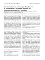
In order to complete the project within the 10 -week timeline, it is essential to devise a well-thought-out plan. The first step towards this plan is to create a specificplan so that each team member can know what he has to do. An efficient method we use is Gantt chart.
Gantt chart is a type a bar chart used for project management that provide a visual representation of a project schedule. Gantt charts help project managers to plan and monitor project progress, and to identify potential delays or issues. They allow project team members to see their individual tasks in the context of the overall project, and to understand how their tasks relate to those of other team members.
<small>Figure 3.1 Project's Gantt chart</small>
</div><span class="text_page_counter">Trang 9</span><div class="page_container" data-page="9">Figure 4.2 Audio Input and Amplifier BlockSystem of
Information
</div><span class="text_page_counter">Trang 10</span><div class="page_container" data-page="10">
<small>Figure 4.4: Arduino uno R3 specifications</small>
<small>Figure 4.5: Arduino uno R3 pin diagram</small>
It comprises 14-digit I/O pins. From these pins, 6-pins can be utilized like PWM outputs. This board includes 14 digital input/ output pins, analog input-6, a USB connection, quazt crystal-16 MHz, a power jack, a USB connection, resonator-16Mhz, a power jack, an ICSP header an RST button.
<small>Figure 4.3 Arduino uno R3</small>
</div><span class="text_page_counter">Trang 11</span><div class="page_container" data-page="11">4.2. PIR SR501
This HC-SR501 PIR sensor module has three output pins Vcc, Output and Groundas shown in the pin diagram above. Since the output pin is 3.3V TTL logic it can be used with any platforms like Arduino, Raspberry, PIC, ARM, 8051 etc..
PIR Sensor Module Pinout Configuration
Pin Name Description
1 Vcc Input voltage is +5V for typical applications. Can range from 4.5V- 12V
2 High/Low Ouput(Dout)
Digital pulse high (3.3V) when triggered (motion detected) digitallow(0V) when idle(no motion detected
3 Ground Connected to ground of circuitPIR Sensor Features
Wide range on input voltage varying from 4.V to 12V (+5V recommended)Output voltage is High/Low (3.3V TTL)
Can distinguish between object movement and human movement.Has to operating modes - Repeatable(H) and Non- Repeatable(H)Cover distance of about 120° and 7 meters
Low power consumption of 65mA6
</div><span class="text_page_counter">Trang 12</span><div class="page_container" data-page="12">Operating temperature from -20° to +80° CelsiusHow to use PIR Motion Sensor
The PIR sensor module can be powered from voltage 4.5V to 20V but, typically 5Vis used. Once the module is powered allow the module to calibrate itself for fewminutes, 2 minutes is a well settled time. Then observe the output on the output pin.Before we analyse the output, we need to know that there are two operating modesin this sensor such as Repeatable(H) and Non- Repeatable(L) and mode. TheRepeatable mode is the default mode.
The output of the sensor can be set by shorting any two pins on the left of themodule as shown below. You can also notice two orange colour potentiometers thatcan be used to set the sensitivity and time which will be explained further below.
Repeatable(H) mode
In Repeatable(H) mode the output pin Dout will go high (3.3V) when a person isdetected within range and goes low after a particular time (time is set by “Off timecontrol” potentiometer). In this mode the output pin will go high irrespective ofwhether the person is still present inside the range or has left the area. Thesensitivity can be set using the “sensitivity control” potentiometer.
7
</div><span class="text_page_counter">Trang 13</span><div class="page_container" data-page="13">Non- Repeatable(L) mode
In “I” mode the output pin Dout will go high (3.3V) when a person is detectedwithin range and will stay high as long as he/she stays within the limit of theSensors range. Once the person has left the area the pin will go low after theparticular time which can be set using the potentiometer. The sensitivity can be setusing the “sensitivity control” potentiometer
There are two important materials present in the sensor one is the pyroelectriccrystal which can detect the heat signatures from a living organism(humans/animals) and the other is a Fresnel lenses which can widen the range ofthe sensor. Yes the white colour things is just a lense that is used to widen the rangeof the sensor, if you remove the lense you can find the Pyroelectric sensor inside itcovered inside a protective metal casing as shown above.
8
</div><span class="text_page_counter">Trang 14</span><div class="page_container" data-page="14">4.3. LED
A light-emitting diode (LED) is a semiconductor device that emits light when an electric current is passed through it. Light is produced when the particles that carry the current (known as electrons and holes) combine together within the
semiconductor material.
Since light is generated within the solid semiconductor material, LEDs are described as solid-state devices. The term solid-state lighting, which also encompasses organic LEDs (OLEDs), distinguishes this lighting technology from other sources that use heated filaments (incandescent and tungsten halogen lamps) or gas discharge (fluorescent lamps).
Different colors
Inside the semiconductor material of the LED, the electrons and holes are containedwithin energy bands. The separation of the bands (i.e. the bandgap) determines the energy of the photons (light particles) that are emitted by the LED.
The photon energy determines the wavelength of the emitted light, and hence its color. Different semiconductor materials with different bandgaps produce different colors of light. The precise wavelength (color) can be tuned by altering the composition of the light-emitting, or active, region.
LEDs are comprised of compound semiconductor materials, which are made up of elements from group III and group V of the periodic table (these are known as III-Vmaterials). Examples of III-V materials commonly used to make LEDs are gallium arsenide (GaAs) and gallium phosphide (GaP).
Until the mid-90s LEDs had a limited range of colors, and in particular commercial blue and white LEDs did not exist. The development of LEDs based on the gallium nitride (GaN) material system completed the palette of colors and opened up many new applications.
9
</div><span class="text_page_counter">Trang 15</span><div class="page_container" data-page="15">Main LED materials
The main semiconductor materials used to manufacture LEDs are:Indium gallium nitride (InGaN): blue, green and ultraviolet high-brightness LEDs
Aluminum gallium indium phosphide (AlGaInP): yellow, orange and red high-brightness LEDs
Aluminum gallium arsenide (AlGaAs): red and infrared LEDsGallium phosphide (GaP): yellow and green LEDs
4.4. 250 ohm resistor
Resistor is an electrical component that reduces the electric current.
The resistor's ability to reduce the current is called resistance and is measured in units of ohms (symbol: Ω).
If we make an analogy to water flow through pipes, the resistor is a thin pipe that reduces the water flow.
10
</div><span class="text_page_counter">Trang 16</span><div class="page_container" data-page="16">pitch between two characters and a space between lines, thus separating characters and lines. The number 1602 means on the display, 2 rows can be showed and 16 characters in each.
Step 1: Components:
-
Arduino Uno board- USB cable - LCD1602
- Potentiometer (50kΩ)- Breadboard - Jumper wires
Step 2: Principle:
Generally, LCD1602 has parallel ports, that is, it would control several pins at the same time. LCD1602 can be categorized into eight-port and four-port connections. If the eight-port connection is used, then all the digital ports of the Arduino Uno board are almost completely occupied. If you want to connect more sensors, there will be noports available. Therefore, the four-port connection is used here for better application.
Pins of LCD1602 and their functionsVSS: connected to ground
VDD: connected to a +5V power supplyVO: to adjust the contrast
RS: A register select pin that controls where in the LCD’s memory you are writing data to. You can select either the data register, which holds what goes on the screen,or an instruction register, which is where the LCD’s controller looks for instructionson what to do next.
R/W: A Read/Write pin to select between reading and writing mode
E: An enabling pin that reads the information when High level (1) is received. The instructions are run when the signal changes from High level to Low level.D0-D7: to read and write data
11
</div><span class="text_page_counter">Trang 17</span><div class="page_container" data-page="17">A and K: Pins that control the LCD backlight. Connect K to GND and A to 3.3v. Open the backlight and you will see clear characters in a comparatively dark environment.
Step 3: The Schematic Diagram
Step 4: Procedures
Connect K to GND and A to 3.3 V, and then the backlight of the LCD1602 will be turned on. Connect VSS to GND and the LCD1602 to the power source. Connect VO to the middle pin of the potentiometer – with it you can adjust the contrast of the screen display. Connect RS to D4 and R/W pin to GND, which means then you can write characters to the LCD1602. Connect E to pin6 and the characters displayed on the LCD1602 are controlled by D4-D7. For programming, it is optimized by calling function libraries.
Step 1: Build the circuit.Step 2: Code
Step 3: Upload the sketch to the Arduino Uno boardClick the Upload icon to upload the code to the control board.
12
</div><span class="text_page_counter">Trang 18</span><div class="page_container" data-page="18">If "Done uploading" appears at
the bottom of the window, it means the sketch has been successfully uploaded.Step 5: Code
4.6. E18-D80NK
The E18-D80NK is an advanced low-cost IR Proximity Sensor with an obstacledetection range of 3 cm to 80 cm. The use of modulated IR signal protects thesensor from the interferences caused by the normal light of a light bulb or thesunlight.
Components Required for interfacing E18-D80NKArduino Nano
E18-D80NK IR SensorJumper WiredBreadboard
E18-D80NK IR Obstacle Avoidance Proximity Sensor
E18-D80NK Infrared Obstacle Avoidance Sensor is a low-cost IR Proximity Sensorwith an adjustable range of 3 cm to 80 cm. The E18-D80 sensor comes with IRTransmitter and IR receiver in one module. The IR transmitter transmits modulatedIR signal, which is then reflected by the object in its path and then detected by thereceiver. This sensor has less interference by sunlight because of the modulated IRlight.
E18-D80 IR Sensor is widely used in robots to avoid obstacles, industrial assemblylines, Reverse Car Parking, and many other automation applications. The detectionrange can be adjusted according to the application using the multi-turn screw that islocated at the back of the sensor. The switching signal output changes according to
13
</div><span class="text_page_counter">Trang 19</span><div class="page_container" data-page="19">the obstacle detection. It remains high when no obstacles and changes to low whenthere are obstacles. A red LED is placed behind the probe that turns high wheneveran obstacle is detected. The E18 sensor operates on 5V and consumes around 5mAto 30mA current without any load.
E18-D80NK IR Proximity Sensor Specifications & Features:Input voltage: 5V DC
Current consumption: > 25mA (min) ~ 100mA (max)Dimension: 1.7cm (diameter) x 4.5cm (length)Cable length: 45cm
Detection of objects: Transparent or OpaqueDiffuse reflective type
Sensing range: 3cm to 80cm (depends on obstacle surface)NPN output (normally high)
Environment temperature: -25 °C ~ 55 °C
Circuit Diagram for Interfacing E18-D80NK Sensor with Arduino
Complete schematic for Interfacing E18-D80NK Proximity Sensor withArduino is given below:
14
</div><span class="text_page_counter">Trang 20</span><div class="page_container" data-page="20">The connection for Interfacing of E18-D80NK IR Sensor with Arduino is very easy,connect the Brown wire of sensor with Arduino 5V pin, connect the Blue wire ofsensor with Arduino’s Ground and connect Black pin of a sensor with a digital pin 7of Arduino Nano.
15
</div><span class="text_page_counter">Trang 21</span><div class="page_container" data-page="21">4.7. MFRC522
MFRC522 IC/Chip: The RC522 RFID Reader Module is based on MFRC522 IC/Chip. This is the high integrated RFID card reader IC/Chip designed by NXP Company, it works on non-contact 13.56mhz communication. It is low power consumption, low cost, and small size read and write chip. The MFRC522 IC supports various types of RFID Tags like MIFARE 1K, MIFARE 4K, MIFARE Mini, and other ISO / IEC 14443 standard protocol-based cards and tags. Also, it supports Mifare series higher speed contactless communication, duplex communication speed up to 424 kb/s. The MFRC522 IC operates at a 13.46 MHz frequency with an operating range of up to 50 mm depending on the antenna size and tuning. The MFRC522 IC supports SPI, UART, and I2C serial communication with the host (Microcontroller like Arduino).
Electrical Parameters
Operating current: 13—26mA/DC 3.3VIdle current: 10-13mA/ DC 3.3VSleep current: <80uA
Peak current: <30mA
Operating frequency: 13.56MHz
Supported Cards: mifare1 S50, mifare1 S70, mifare UltraLight, mifare Pro, mifare Desfire
Physical features: size: 40mm×60mm
Ambient operating temperature: - 20-80 degrees centigradeAmbient storage temperature: - 40-85 degrees centigradeAmbient relative humidity: 5%—95%
17
</div>