Desiccant enhanced evaporative air-conditioning (DEVap): evaluation of a new concept in ultra efficient air conditioning docx
Bạn đang xem bản rút gọn của tài liệu. Xem và tải ngay bản đầy đủ của tài liệu tại đây (25.4 MB, 61 trang )
Desiccant Enhanced
Evaporative Air-Conditioning
(DEVap): Evaluation of a New
Concept in Ultra Efficient Air
Conditioning
Eric Kozubal, Jason Woods, Jay Burch,
Aaron Boranian, and Tim Merrigan
NREL is a national laboratory of the U.S. Department of Energy, Office of Energy
Efficiency & Renewable Energy, operated by the Alliance for Sustainable Energy, LLC.
Technical Report
NREL/TP-5500-49722
January 2011
Contract No. DE-AC36-08GO28308
Simpo PDF Merge and Split Unregistered Version -
Desiccant Enhanced
Evaporative Air-Conditioning
(DEVap): Evaluation of a New
Concept in Ultra Efficient Air
Conditioning
Eric Kozubal, Jason Woods, Jay Burch,
Aaron Boranian, and Tim Merrigan
Prepared under Task No. ARRB2206
NREL is a national laboratory of the U.S. Department of Energy, Office of Energy
Efficiency & Renewable Energy, operated by the Alliance for Sustainable Energy, LLC.
National Renewable Energy Laboratory
Technical Report
1617 Cole Boulevard
NREL/TP-5500-49722
Golden, Colorado 80401
January 2011
303-275-3000 • www.nrel.gov
Contract No. DE-AC36-08GO28308
Simpo PDF Merge and Split Unregistered Version -
NOTICE
This report was prepared as an account of work sponsored by an agency of the United States government.
Neither the United States government nor any agency thereof, nor any of their employees, makes any warranty,
express or implied, or assumes any legal liability or responsibility for the accuracy, completeness, or usefulness of
any information, apparatus, product, or process disclosed, or represents that its use would not infringe privately
owned rights. Reference herein to any specific commercial product, process, or service by trade name,
trademark, manufacturer, or otherwise does not necessarily constitute or imply its endorsement, recommendation,
or favoring by the United States government or any agency thereof. The views and opinions of authors
expressed herein do not necessarily state or reflect those of the United States government or any agency thereof.
Available electronically at
Available for a processing fee to U.S. Department of Energy
and its contractors, in paper, from:
U.S. Department of Energy
Office of Scientific and Technical Information
P.O. Box 62
Oak Ridge, TN 37831-0062
phone: 865.576.8401
fax: 865.576.5728
email:
mailto:
Available for sale to the public, in paper, from:
U.S. Department of Commerce
National Technical Information Service
5285 Port Royal Road
Springfield, VA 22161
phone: 800.553.6847
fax: 703.605.6900
email:
online ordering:
Cover Photos: (left to right) PIX 16416, PIX 17423, PIX 16560, PIX 17613, PIX 17436, PIX 17721
Printed on paper containing at least 50% wastepaper, including 10% post consumer waste.
Simpo PDF Merge and Split Unregistered Version -
Executive Summary
NREL has developed the novel concept of a desiccant enhanced evaporative air conditioner
(DEVap) with the objective of combining the benefits of liquid desiccant and evaporative
cooling technologies into an innovative “cooling core.” Liquid desiccant technologies have
extraordinary dehumidification potential, but require an efficient cooling sink. Today’s
advanced indirect evaporative coolers provide powerful and efficient cooling sinks, but are
fundamentally limited by the moisture content in the air. Alone, these coolers can achieve
temperatures that approach the dew point of the ambient air without adding humidity; however,
they cannot dehumidify. Use of stand-alone indirect evaporative coolers is thus relegated to arid
or semiarid geographical areas.
Simply combining desiccant-based dehumidification and indirect evaporative cooling
technologies is feasible, but has not shown promise because the equipment is too large and
complex. Attempts have been made to apply liquid desiccant cooling to an indirect evaporative
cooler core, but no viable design has been introduced to the market. DEVap attempts to clear
this hurdle and combine, in a single cooling core, evaporative and desiccant cooling. DEVap’s
crucial advantage is the intimate thermal contact between the dehumidification and the cooling
heat sink, which makes dehumidification many times more potent. This leads to distinct
optimization advantages, including cheaper desiccant materials and a small cooling core. The
novel design uses membrane technology to contain liquid desiccant and water. When used to
contain liquid desiccant, it eliminates desiccant entrainment into the airstream. When used to
contain water, it eliminates wet surfaces, prevents bacterial growth and mineral buildup, and
avoids cooling core degradation.
DEVap’s thermodynamic potential overcomes many shortcomings of standard refrigeration-
based direct expansion cooling. DEVap decouples cooling and dehumidification performance,
which results in independent temperature and humidity control. The energy input is largely
switched away from electricity to low-grade thermal energy that can be sourced from fuels such
as natural gas, waste heat, solar, or biofuels. Thermal energy consumption correlates directly to
the humidity level in the operating environment. Modeling at NREL has shown that the yearly
combined source energy for the thermal and electrical energy required to operate DEVap is
expected to be 30%–90% less than state-of-the-art direct expansion cooling (depending on
whether it is applied in a humid or a dry climate). Furthermore, desiccant technology is a new
science with unpracticed technology improvements that can reduce energy consumption an
additional 50%. And unlike most heating, ventilation, and air-conditioning systems, DEVap uses
no environmentally harmful fluids, hydrofluorocarbons, or chlorofluorocarbons; instead, it uses
water and concentrated salt water.
DEVap is novel and disruptive, so bringing it into the entrenched conventional air conditioner
market will create some market risk. Designing and installing a new DEVap system requires
retraining. DEVap has unknown longevity and reliability compared to standard A/C. The
availability of natural gas or other thermal energy sources may be an issue in certain places.
However, DEVap does not require a large outdoor condenser, but instead uses a much smaller
desiccant regenerator that can be placed inside or outside, and can be integrated with solar and
waste heat. If these risks can be properly addressed, the DEVap air conditioner concept has
i
Simpo PDF Merge and Split Unregistered Version -
strong potential to significantly reduce U.S. energy consumption and provide value to energy
companies by reducing summertime electric power demand and resulting grid strain.
NREL has applied for international patent protection for the DEVap concept (see
www.wipo.int/pctdb/en/wo.jsp?WO=2009094032).
ii
Simpo PDF Merge and Split Unregistered Version -
Acronyms and Abbreviations
AAHX air-to-air heat exchanger
AILR AIL Research
A/C air-conditioning
CHP combined heat and power
COP coefficient of performance
DEVap desiccant-enhanced evaporative air conditioner
DOE U.S. Department of Energy
DX direct expansion air conditioner
HMX heat and mass exchanger
HVAC heating, ventilation, and air-conditioning
IRR internal rate of return
LCC life cycle cost
LDAC liquid desiccant air conditioner
NREL National Renewable Energy Laboratory
RH relative humidity
RTU rooftop unit
SEER seasonal energy efficiency ratio
SHR sensible heat ratio
iii
Simpo PDF Merge and Split Unregistered Version -
Contents
Executive Summary i
Acronyms and Abbreviations iii
1.0 Introduction 1
1.1 Intention 1
1.2 Background 1
2.0 Research Goals 3
2.1 Air-Conditioning Functional Goals 3
2.2 How Direct Expansion Air-Conditioning Achieves Performance Goals 5
2.3 The DEVap Process 7
2.3.1 Commercial-Grade Liquid Desiccant Air Conditioner Technology 7
2.3.2 DEVap Process: Air Flow Channel Using Membranes (NREL Patented Design) 12
2.4 DEVap Cooling Performance 16
2.5 DEVap Implementation 17
2.5.1 New and Retrofit Residential 17
2.5.2 New and Retrofit Commercial 19
3.0 Modeling 21
3.1 Fundamental Modeling for the DEVap Cooling Core 21
3.2 Building Energy Models 22
3.2.1 Residential New and Retrofit 22
3.2.2 New and Retrofit Commercial – EnergyPlus-Generated Load Following 24
3.3 Cost Model 24
3.3.1 Initial Cost Estimates 24
3.3.2 Economic Analysis Assumptions for New and Retrofit Residential 25
3.3.3 Economic Analysis Assumptions for New and Retrofit Commercial 26
3.4 Cooling Performance 26
3.4.1 New Residential 28
3.4.2 Retrofit Residential 30
3.4.3 New and Retrofit Commercial 31
3.5 Energy Performance 32
3.5.1 New Residential 32
3.5.2 Retrofit Residential 35
3.5.3 New and Retrofit Commercial 37
3.6 Residential Cost Performance 38
3.7 Commercial Cost Performance 41
4.0 Risk Assessment 42
4.1 Technology Risks 42
4.2 Market and Implementation Risks 43
4.3 Risk to Expected Benefits 44
5.0 Future Work 46
5.1 Laboratory DEVap A/C Demonstration 46
5.2 Regeneration Improvements 46
5.3 Solar Thermal Integration 46
iv
Simpo PDF Merge and Split Unregistered Version -
6.0 Conclusions 47
6.1 Residential Performance Comparison 47
6.2 Commercial Performance Comparison 47
6.3 Residential Cost Comparison 47
6.4 Commercial Cost Comparison 48
6.5 Risk Assessment 48
7.0 References 49
8.0 Resources Not Cited 51
Appendix A Data Tables 52
A.1 Detailed Specifications for Retrofit Residential Building 52
A.2 Detailed Specifications for New Residential Building 52
A.3 Energy Performance – New Residential 53
A.4 Energy Performance – Retrofit Residential 55
A.5 Economics – New Residential 57
A.6 Economics – Retrofit Residential 58
A.7 Cost Estimates 59
A.8 Utility Prices From Utility Tariffs for 2010 60
v
Simpo PDF Merge and Split Unregistered Version -
Figures
Figure 2-1 ASHRAE comfort zone and 60% RH limit for indoor air quality 4
Figure 2-2 SHR lines plotted on a psychrometric chart with room air at 76°F and 60% RH 5
Figure 2-3 Lennox DX A/C with Humiditrol condenser reheat coil (Lennox Commercial 2010) 6
Figure 2-4 Psychrometric chart showing the dehumidification process using desiccants 8
Figure 2-5 Desiccant reactivation using single-effect scavenging air regenerator 9
Figure 2-6 Major components and packaging of the AILR LDAC (Photograph shows packaged
HMXs, water heater and cooling tower) 10
Figure 2-7 LDAC schematic 11
Figure 2-8 Calculated two-stage regenerator moisture removal rate and efficiency performance 12
Figure 2-9 Physical DEVap concept description 13
Figure 2-10 Scanning electron microscope photograph of a micro porous membrane (Patent Pending,
Celgard product literature) 14
Figure 2-11 DEVap HMX air flows 15
Figure 2-12 DEVap enhancement for LDAC 16
Figure 2-13 DEVap cooling process in a typical Gulf Coast design condition 17
Figure 2-14 Example diagram of a residential installation of DEVap A/C showing the solar option 18
Figure 2-15 Example diagram of a packaged DEVap A/C 19
Figure 2-16 Example diagram of a commercial installation of DEVap A/C showing the solar and
CHP options 20
Figure 3-1 Temperature and humidity profiles of DEVap process using the Engineering Equation
Solver model 21
Figure 3-2 DEVap cooling core design 22
Figure 3-3 Residential/new – Houston simulation showing the return air and supply air from the
DEVap A/C 27
Figure 3-4 Return and supply air from the DX A/C and dehumidifier (shown as “DH”) in a new
residential building in Houston 28
Figure 3-5 Effect of a whole-house dehumidifier when used with DX A/C in a new residential
building in Houston 28
Figure 3-6 Indoor RH histograms for Houston throughout the year 29
Figure 3-7 Indoor RH histograms for Houston in June–August 29
Figure 3-8 Houston DEVap A/C SHR bins for meeting cooling load 30
Figure 3-9 Indoor RH histograms for Houston throughout the year 30
Figure 3-10 Indoor RH histograms for Houston in June–August 31
Figure 3-11 RH histogram for a small office benchmark in Houston 31
Figure 3-12 Latent load comparison and resultant space RH in Houston 32
Figure 3-13 A/C power comparison in Houston for residential new construction 33
vi
Simpo PDF Merge and Split Unregistered Version -
Figure 3-14 Peak power in all cities, residential new construction 33
Figure 3-15 Source energy in all cities, residential new construction 34
Figure 3-16 Water use (evaporation) in all cities, residential new construction 34
Figure 3-17 A/C power comparison in Houston for residential retrofit case 35
Figure 3-18 Peak power in all cities for residential retrofit case 35
Figure 3-19 Source energy in all cities for residential retrofit case 36
Figure 3-20 Water use (evaporation) in all cities, residential retrofit construction 36
Figure 3-21 A/C power comparison for a small office benchmark in Phoenix 37
Figure 3-22 A/C power comparison for a small office benchmark in Houston 37
Figure 3-23 Annualized cost comparison for residential new construction 39
Figure 3-24 LCCs for residential new construction for Phoenix (hot, dry) and Houston (hot, humid) 39
Figure 3-25 Cost comparison for residential retrofit 40
Figure 3-26 LCC breakdown for retrofit for Phoenix (hot, dry) and Houston (hot, humid) 41
Figure 4-1 U.S. water use profile 43
Figure 5-1 Vapor compression distillation regenerator latent COP using natural gas (AILR 2002) 46
Tables
Table 2-1 SHRs of Typical Climate Zones (ASHRAE Zones Noted) 5
Table 2-2 Technology Options for Residential and Commercial Buildings 6
Table 2-3 Source Energy Efficiency Comparison for Commercial Equipment 7
Table 2-4 Technology Options for Residential and Commercial Buildings 10
Table 3-1 DEVap 1-Ton Prototype Dimensions 22
Table 3-2 A/C System Capacity in Each City Simulated 23
Table 3-3 Modeled Pressure Losses at Maximum Air Flow Rate in Pascals 23
Table 3-4 DEVap Retail Cost Estimate, Immature Product 25
Table 3-5 Initial DX A/C Cost Estimate 25
Table 3-6 Economic Analysis Assumptions 25
Table 3-7 Source Energy Conversion Factors (Deru et al, 2007) 32
Table 3-8 Results Summary for Phoenix 38
Table 3-9 Results Summary for Houston 38
Table 3-10 Economic Analysis for Houston 41
Table 3-11 Economic Analysis for Phoenix 41
Table 4-1 Technical Risk Matrix for DEVap A/C 43
Table 4-2 Market and Implementation Risk Matrix for DEVap A/C 44
vii
Simpo PDF Merge and Split Unregistered Version -
1.0 Introduction
1.1 Intention
Our intent is to describe the desiccant enhanced evaporative air conditioner (DEVap A/C)
concept. To do this, we must give background in A/C design and liquid desiccant technology.
After which, we can describe the concept which consists of a novel A/C geometry and a resulting
process. We do this by:
• Discussing the goals of an air conditioner in comparison to expectations
• Discussing the benefits of combining desiccant technology and indirect evaporative
cooling
• Describing the DEVap A/C process
• Providing a physical description of the DEVap device
• Discussing the energy savings potential
• Assessing the risks of introducing this novel concept to the marketplace
• Discussing future work to bring this concept to the marketplace.
This information is intended for an audience with technical knowledge of heating, ventilating,
and air-conditioning (HVAC) technologies and analysis.
1.2 Background
Today’s A/C is primarily based on the direct expansion (DX) or refrigeration process, which was
invented by Willis Carrier more than 100 years ago. It is now so prevalent and entrenched in
many societies that it is considered a necessity for maintaining efficient working and living
environments. DX A/C has also had more than 100 years to be optimized for cost and
thermodynamic efficiency, both of which are nearing their practical limits. However, the
positive impact of improved comfort and productivity does not come without consequences.
Each year, A/C uses approximately 4 out of 41 quadrillion Btu (quads) of the source energy used
for electricity production in the United States alone, which results in the release of about 380
MMT of carbon dioxide into the atmosphere (DOE 2009).
R-22 (also known as Freon) as a refrigerant for A/C is quickly being phased out because of its
deleterious effects on the ozone layer. The most common remaining refrigerants used today (R-
410A and R-134A) are strong contributors to global warming. Their global warming potentials
are 2000 and 1300, respectively (ASHRAE 2006). Finding data on air conditioner release rates
is nearly impossible, as they are generally serviced only when broken and refrigerant recharge is
not accurately accounted for. A typical residential size A/C unit may have as much as 13 pounds
of R-410A, and a 10-ton commercial A/C has as much as 22 pounds.
Water is not commonly considered to be a refrigerant, but the American Society of Heating,
Refrigerating and Air-Conditioning Engineers (ASHRAE 2009) recognizes it as the refrigerant
R-718. Evaporative cooling uses the refrigerant properties of water to remove heat the same way
DX systems use the refrigeration cycle. Water evaporates and drives heat from a first heat
reservoir, and then the vapor is condensed into a second reservoir. Evaporative cooling is so
efficient because atmospheric processes in nature, rather than a compressor and condenser heat
exchanger, perform the energy-intensive process of recondensing the refrigerant. Water is
delivered to the building as a liquid via the domestic water supply.
1
Simpo PDF Merge and Split Unregistered Version -
NREL’s thermally activated technology program has been developing, primarily with AIL
Research (AILR) as our industry partner, liquid-desiccant-based A/C (LDAC) for more than 15
years. The technology uses liquid desiccants to enable water as the refrigerant in lieu of
chlorofluorocarbon-based refrigerants to drive the cooling process. The desiccants are strong
salt water solutions. In high concentrations, desiccants can absorb water from air and drive
dehumidification processes; thus, evaporative cooling devices can be used in novel ways in all
climates. Thermal energy dries the desiccant solutions once the water is absorbed. LDACs
substitute most electricity use with thermal energy, which can be powered by many types of
energy sources, including natural gas, solar thermal, biofuels, and waste heat. The benefits
include generally lower source energy use, much lower peak electricity demand, and lower
carbon emissions, especially when a renewable fuel is used.
2
Simpo PDF Merge and Split Unregistered Version -
2.0 Research Goals
2.1 Air-Conditioning Functional Goals
In developing a novel air conditioner based on principles that are inherently different than
traditional A/C, we must consider the design goals for a new conditioner to be successful. We
first define what an air conditioning system does in building spaces only.
Today’s A/C systems:
• Maintain a healthy building environment.
o In commercial and new residential, A/C provides ventilation air to maintain
indoor air quality.
o A/C maintains humidity to prevent mold growth, sick building syndrome, etc.
• Maintain human comfort by providing
o Temperature control (heat removal)
o Humidity control (water removal)
o Some air filtering (particulate removal).
• Distribute air throughout the space to encourage thermal uniformity.
• In commercial applications, provide make-up air to accommodate exhaust air (EA) flows.
Today’s A/C systems have:
• Reasonable operations and maintenance (O&M) costs:
o Cost of energy to operate
o Ease of maintenance (for which the expectation is maintain at failure)
• Reasonable size and first cost
o Must fit in an acceptable space
o Must be cost effective compared to minimum efficiency A/C equipment.
At a minimum, a new air conditioner must be capable of meeting or surpassing these
expectations when designed into an A/C system.
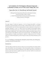
For human comfort and building health, A/C is commonly expected to maintain a humidity level
of less than 60% and inside the ASHRAE comfort zone (ASHRAE Standard 55-2004) seen in
Figure 2-1. The comfort zone is only a general requirement and may be strongly influenced by
occupant activity and clothing level. The summer zone is primarily for sedentary activity with a
t-shirt and trousers. Often, temperatures are set to lower set points because activity generally
increases. The winter zone is for significantly heavier clothing, but still sedentary activity. The
60% relative humidity (RH) line does intersect the comfort zones, and thus influences how the
A/C must react to provide proper building indoor air quality despite human comfort concerns.
3
Simpo PDF Merge and Split Unregistered Version -
Psychrometric Chart at 0 ft Elevation (1.013 bar)
(14.7 psia)
Psychrometric Chart at 0 ft Elevation (14.7 psia)
160
Comfort Zone (Summer)
Comfort Zone (Winter)
60%
50 60 70 80 90 100
140
120
100
ω (grains/lb)
80
60
40
20
0
Dry Bulb Temperature (
°F)
Figure 2-1 ASHRAE comfort zone and 60% RH limit for indoor air quality
Two types of space loads affect building humidity and temperature:
• Sensible load. This is the addition of heat to the building space and comes from a variety
of sources (e.g., sunlight, envelope, people, lights, and equipment).
• Latent load. This is the addition of moisture to the building space and comes from
multiple sources (e.g., infiltration, mechanical ventilation, and occupant activities).
Sensible and latent loads combined form the total load. The sensible load divided by the total
load is the sensible heat ratio (SHR). A line of constant SHR is a straight line on a
psychrometric chart, indicating simultaneous reduction in temperature and humidity. The
building loads determine the SHR and an air conditioner must react to it accordingly to maintain
temperature and humidity. To match the space load, an A/C system must provide air along a
constant SHR originating from the space condition (76°F and varying RH). To meet an SHR of
0.7, one must follow the SHR line of 0.7 to a delivery condition that is lower in temperature and
humidity. Figure 2-2 and Figure 2–3 show the implications of space SHR on an A/C system by
illustrating how 60% and 50% RH levels influence A/C performance. Humidity is typically
removed by cooling the air below the room air dew point. Thus, the saturation condition (black
line at 100% RH) is the potential to dehumidify. The intersection of the SHR lines and the
saturation line gives the “apparatus dew point” at which the cooling coil will operate. Reducing
RH from 60% to 50% requires that the apparatus dew point change from 56°F to 47°F at a
constant SHR of 0.7. When the SHR drops below 0.6 (which is typical of summer nights and
swing seasons when sensible gains are low), the humidity cannot be maintained below 60% RH
with standard DX cooling alone.
4
Simpo PDF Merge and Split Unregistered Version -
Psychrometric Chart at 0 ft Elevation (1.013 bar)
Psychrometric Chart at 0 ft Elevation (14.7 psia)
150
125
100
75
50
25
0
Dry Bulb Temperature (°F)
Figure 2-2 SHR lines plotted on a psychrometric chart with room air at 76°F and 60% RH
2.2 How Direct Expansion Air-Conditioning Achieves Performance Goals
For most of the A/C market, refrigeration-based (DX) cooling is the standard, and provides a
point of comparison for new technologies. To describe the benefits and improvements of
DEVap A/C technology, we must discuss standard A/C.
Standard A/C reacts to SHR by cooling the air sensibly and, if dehumidification is required, by
cooling the air below the dew point. This removes water at a particular SHR. Maintaining a
space at 76°F and 60% RH (see Figure 2-2) requires the A/C to deliver air along the relevant
SHR line. If the SHR line does not intersect the saturation line (as in the case of SHR = 0.5),
standard DX A/C cannot meet latent load, and the RH will increase. If humidity is maintained at
50% RH (Figure 2–3), standard DX A/C cannot maintain RH when the space SHR reaches
below about 0.7.
Building simulation results provide insight into typical SHRs in residential and commercial
buildings. Table 2–1 shows typical SHR ranges in a few U.S. climates. Humidity control with
standard DX A/C becomes an issue in climate zones 1A–5A and 4C. Thus, humidity control
must be added. Western climates in the hot/dry or hot/monsoon climates have sufficiently high
SHR and generally do not require additional humidity control.
Table 2-1 SHRs of Typical Climate Zones (ASHRAE Zones Noted)
Return or Room Air
40 50 60 70 80 90 100
ω (grains/lb)
Climate
Typical SHR Range
1A–3A. Hot/Humid (e.g., Houston)
0.0–0.9
4A–5A. Hot/Humid/Cold (e.g., Chicago)
0.0–1.0
2B. Hot/Monsoon (e.g., Phoenix)
0.7–1.0
3B–5B: Hot/Dry (e.g., Las Vegas)
0.8–1.0
4C. Marine (e.g., San Francisco)
0.5–1.0
5
Simpo PDF Merge and Split Unregistered Version -
In the A/C industry, common technologies for meeting lower SHRs are:
1. DX + wrap-around heat exchanger or latent wheel
o Trane CDQ (wrap-around active/desiccant wheel) (see Trane 2008)
o Munters Wringer (wrap-around sensible wheel) (see Munters Web site
www.munters.us/en/us/)
2. DX + active wheel
o Munters DryCool system using condenser reheat to reactivate an active desiccant
wheel (see Munters Web site www.munters.us/en/us/)
3. DX + reheat
o Lennox Humiditrol with condenser reheat (see Figure 2-3)
4. DX + ice or apparatus dewpoint < 45°F
o Four Seasons
o Ice Energy Ice Bear energy storage module (see Ice Energy 2010)
5. DX + space dehumidifier
Figure 2-3 Lennox DX A/C with Humiditrol condenser reheat coil (Lennox Commercial 2010)
Humidity control options for various building types are shown in Table 2-2.
Table 2-2 Technology Options for Residential and Commercial Buildings
Building Type
New and Retrofit
Residential 3. DX + reheat
5. DX + space dehumidifier
Commercial
1. DX + wrap-around heat exchanger
2. DX + active wheel
3. DX + reheat
4. DX + ice or apparatus dew point < 45°F
5. DX + space dehumidifier
Commercial buildings can, in most cases, use all technology options. Residential systems align
with options 3 and 5. These technologies do not come without penalties, which are always
increased energy use and added upfront costs. With options 1 and 2, the primary energy use
6
Simpo PDF Merge and Split Unregistered Version -
comes from significant increase in fan power to blow air through the various wheel types.
Option 3, DX + reheat, is the most common, but essentially erases the cooling done by the DX
circuit without significant DX cycle efficiency change. This creates an air conditioner rated at 3
tons that delivers 30% less cooling (or about 2 tons) with the same energy use as the original 3-
ton system. DX + apparatus dew point < 45°F has reduced cycle efficiency because deep
cooling is provided. DX + dehumidifier is much like DX + reheat, but the dehumidifier is a
specialized DX system used to deeply dry the air before reheating.
Options 1, 2, and 4 are usually chosen to pretreat outdoor air (OA) in a dedicated outdoor air
system, which in all but a few special cases (commercial kitchens and supermarkets with large
exhaust flows) will not control indoor humidity. However, these technologies do meet large load
profiles and can reduce the latent load requirements on the smaller DX systems serving the same
spaces. For space humidity control, most people choose DX + reheat for commercial spaces and
DX + reheat or dehumidifier for residential spaces. In all cases, latent cooling follows sensible
cooling. Thus, sensible cooling is often too high and must either be reheated or combined with a
desiccant to lower the SHR.
Table 2-3 Source Energy Efficiency Comparison for Commercial Equipment
(Kozubal 2010)
DX With Sensible DX With Desiccant DX With Wrap-
Humidity Level Gas Reheat Rotor and Condenser Around Desiccant
(dry bulb/wet bulb)
(200 cfm/ton)
Heat Regeneration
Rotor
High humidity (87°/77.3°F) 65% 75% N/A
Medium humidity (80°/71°F) 55% 65% 85%
Modest humidity (80°/68°F) 48% 46% 83%
2.3 The DEVap Process
2.3.1 Commercial-Grade Liquid Desiccant Air Conditioner Technology
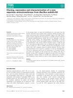
Desiccants reverse the paradigm of standard DX A/C by first dehumidifying, and then sensibly
cooling to the necessary level. Desiccant at any given temperature has a water vapor pressure
equilibrium that is roughly in line with constant RH lines on a psychrometric chart (Figure 2-4).
The green lines show the potential for two common types of liquid desiccants, lithium chloride
(LiCl) and calcium chloride (CaCl
2
). If the free surface of the desiccant is kept at a constant
temperature, the air will be driven to that condition. If used with an evaporative heat sink at 55°–
85°F, the air can be significantly dehumidified and dew points < 32°F are easily achieved. The
blue arrow shows the ambient air being driven to equilibrium with LiCl with an evaporative heat
sink. At this point, the air can be sensibly cooled to the proper temperature. This type of
desiccant A/C system decouples the sensible and latent cooling, and controls each independently.
During the dehumidification process, the liquid desiccant (about 43% concentration by weight
salt in water solution) absorbs the water vapor and releases heat. The heat is carried away by a
heat sink, usually chilled water from a cooling tower. As water vapor is absorbed from the
ambient air, it dilutes the liquid desiccant and decreases its vapor pressure and its ability to
absorb water vapor. Lower concentrations of desiccant come into equilibrium at higher ambient
air RH levels. Dehumidification can be controlled by the desiccant concentration that is supplied
to the device. The outlet humidity level can be controlled by controlling the supplied desiccant
concentration or decreasing the flow of highly concentrated desiccant. The latter allows the
7
Simpo PDF Merge and Split Unregistered Version -
8
highly concentrated desiccant to quickly be diluted and thus “act” as a weaker desiccant solution
in the device.
Figure 2-4 Psychrometric chart showing the dehumidification process using desiccants
Absorption will eventually weaken the desiccant solution and reduce its dehumidifying potential;
the desiccant must then be regenerated to drive off the absorbed water. Thermal regeneration is
the reverse: In this process, the desiccant is heated to a temperature at which the equilibrium
vapor pressure is above ambient. The vapor desorbs from the desiccant and is carried away by
an air stream (see Figure 2-5). Sensible heat is recovered by first preheating the ambient air
using an air-to-air heat exchanger (AAHX). The air comes into heat and mass exchange with the
hot desiccant (in this example at 190°F) and carries the desorbed water vapor away from the
desiccant. Sensible heat is recovered by taking the hot humid air to preheat the incoming air
through the AAHX. The change in enthalpy of the air stream represents the majority of the
thermal input. Small heat loss mechanisms are not represented in the psychrometric process.
The process uses hot water or steam to achieve a latent coefficient of performance (COP) of 0.8–
0.94 depending on ultimate desiccant concentration. Latent COP is defined as:
COP is maximized by maximizing the regeneration temperature and change in concentration
while minimizing the ultimate desiccant concentration. Including the COP of the water heater
(about 0.82), a typical combined latent COP is 0.82 × 0.85 = 0.7.
0
20
40
60
80
100
120
140
160
30 40 50 60 70 80 90 100 110 120
ω (grains/lb)
Dry Bulb Temperature (°F)
Psychrometric Chart at 0 ft Elevation (1.013 bar)
Room or Return Air
(14.7 psia)
Psychrometric Chart at 0 ft Elevation (14.7 psia)
Simpo PDF Merge and Split Unregistered Version -
Psychrometric Chart at 0 ft Elevation (1.013 bar)
(14.7 psia)
Psychrometric Chart at 0 ft Elevation (14.7 psia)
1000
30 40 50 60 70 80
90 100 110 120 130
140 150 160 170 180 190 200 210
Enthalpy = 45 BTU/lbm
Enthalpy = 60.6 BTU/lbm
Enthalpy = 192.5 BTU/lbm
Ambien t Air
SR Exhaust Air
Majority of
Heat Input
900
800
700
600
500
400
ω (grains/lb)
300
200
100
0
Dry Bulb Temperature (°F)
Figure 2-5 Desiccant reactivation using single-effect scavenging air regenerator
The AILR LDAC technology uses novel heat and mass exchangers (HMXs) to perform these
two processes (see Figure 2-6), which show the desiccant conditioner and scavenging air
regenerator. The liquid desiccant is absorbed into the conditioner (absorber) where the inlet
ambient air is dehumidified. The liquid desiccant is regenerated in the regenerator (desorber)
where the water vapor desorbs into the EA stream. This technology is called low flow liquid
desiccant A/C, because the desiccant flow is minimized in both HMXs to the flow rate needed to
absorb the necessary moisture from the air stream. The HMXs must therefore have integral
heating and cooling sources (55°–85°F cooling tower water is supplied to the conditioner). The
regenerator uses hot water or hot steam at 160°–212°F. The cooling or heating water flows
internal to the heat exchange plates shown. The desiccant flows on the external side of the HMX
plates. The plates are flocked, which effectively spreads the desiccant. This creates direct
contact surfaces between the air and desiccant flows. The air passes between the plates, which
are spaced 0.25 in. apart. Figure also shows a 20-ton packaged version on a supermarket in
Los Angeles, California. Lowenstein (2005) provides more detailed descriptions of these
devices.
9
Simpo PDF Merge and Split Unregistered Version -
cool, dry ventilation
Regenerator
delivered to building
Cooling Tower
Water heater
Conditioner
Economizer
hot and
humid
air
humid
exhaust
heating
water
chilled
water
Figure 2-6 Major components and packaging of the AILR LDAC (Photograph shows packaged
HMXs, water heater and cooling tower)
(Photos used with permission from AIL Research)
A double-effect regenerator expands on the scavenging air regenerator by first boiling the water
out of the liquid desiccant solution (250°–280°F) and reusing the steam by sending it through the
scavenging air regenerator. This two-stage regeneration system can achieve a latent COP of 1.1–
1.4. NREL is working with AILR to develop this product. A typical solar regenerator would
consist of either a hot water supply to a scavenging regenerator (which would result in a single-
effect device that would have about a 60% solar conversion efficiency based on absorber area).
We are currently monitoring more advanced concepts that generate steam by boiling either water
or liquid desiccant internal to a Dewar-style evacuated tube. If filled with water to create steam,
efficiency up to 70% is possible. An advanced version would boil desiccant directly in the solar
collector to create steam that is then used in the scavenging regenerator. This would increase
solar conversion efficiency to 120%. This work is ongoing and results are not yet available.
Table 2-4 Technology Options for Residential and Commercial Buildings
(Based on NREL calculations and laboratory data, available on request)
Regenerator
COP
Solar
60%–120% solar conversion
Single effect*
0.7–0.8
Double effect*
1.1–1.4
* Based on the higher heating value of natural gas
For the low-flow LDAC, the regenerator and conditioner systems are shown connected in Figure
2-7, which illustrates the three basic ways to regenerate the desiccant system with a thermal
source: solar, water heater, and a double effect. The water heater or boiler can be fueled by
many sources, including natural gas, combined heat and power (CHP), or even biofuels.
Also shown is the desiccant storage option that allows an A/C system to effectively bridge the
time gap between thermal energy source availability and cooling load. Desiccant storage at 8%
concentration differential will result in about 5 gal/latent ton·h. In comparison, ice storage is
approximately 13–15 gal/ton·h (theoretically 10 gal/ton·h, but in practice only 67% of the
10
Simpo PDF Merge and Split Unregistered Version -
volume is frozen (Ice Energy 2010). This storage can be useful to enable maximum thermal use
from solar or on-site CHP. LDACs leverage the latent storage capacity by producing more total
cooling than the stored latent cooling. For example, an LDAC may use 2 ton·h of latent storage,
but deliver 4 ton·h of total cooling. This is derived from an additional 2 tons of sensible cooling
accomplished by the evaporative cooling system.
Figure 2-7 LDAC schematic
The latent COP for DEVap is 1.2–1.4, because it requires only modest salt concentration to
function properly (30%–38% LiCl). Figure 2-8 shows the calculated efficiency of a two-stage
regenerator using natural gas as the heat source. Moisture removal rate is also shown where the
nominal rate is 3 tons of latent removal.
11
Simpo PDF Merge and Split Unregistered Version -
2 Stage Regenerator Performance
(30 kbtu gas input, T
amb,wb
= 78°F, ∆C
LiCl
= 8% )
4.00
3.50
3.00
2.50
2.00
MRR
1.50
COP_Latent
1.00
0.50
0.00
Inlet Desiccant Concentration (% by weight)
Figure 2-8 Calculated two-stage regenerator moisture removal rate and efficiency performance
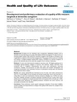
2.3.2 DEVap Process: Air Flow Channel Using Membranes (NREL Patented
Design)
This section describes how the LDAC process is enhanced with NREL’s DEVap concept. The
DEVap process follows:
1. Ventilation air [1] and warm indoor air [2] are mixed into a single air stream.
2. This mixed air stream (now the product air) is drawn through the top channel in the heat
exchange pair.
3. The product air stream is brought into intimate contact with the drying potential of the
liquid desiccant [d] through a vapor-permeable membrane [e].
4. Dehumidification [ii] occurs as the desiccant absorbs water vapor from the product air.
5. The product air stream is cooled and dehumidified, then supplied to the building space
[3].
6. A portion of the product air, which has had its dew point reduced (dehumidified), is
drawn through the bottom channel of the heat exchange pair and acts as the secondary air
stream.
7. The secondary air stream is brought into intimate contact with the water layer [c] through
a vapor-permeable membrane [b].
8. The two air streams are structurally separated by thin plastic sheets [a] through which
thermal energy flows, including the heat of absorption [i].
9. Water evaporates through the membranes and is transferred to the air stream [iii].
10. The secondary air stream is exhausted [4] to the outside as hot humid air.
MRR (tons) and Latent COP (Site)
20% 25% 30% 35% 40%
12
Simpo PDF Merge and Split Unregistered Version -
d. Liquid
Desiccant
i. Heat Transfer
1. Ventilation Air
2. Warm Indoor Air
4. Humid Exhaust
iii. Water
Evaporation
(Cooling Effect)
3. Cool-Dry
Supply Air
b. Membrane
c. Water
ii. Dehumidification
a. Plastic
Sheets
e. Membrane
Figure 2-9 Physical DEVap concept description
NREL has applied for international patent protection for the DEVap concept and variations
(Alliance for Sustainable Energy LLC 2008).
The water-side membrane implementation of DEVap is part of the original concept, but is not a
necessary component. Its advantages are:
• Complete water containment. It completely solves problems with sumps and water
droplets entrained into the air stream.
• Dry surfaces. The surface of the membrane becomes a “dry to the touch” surface that is
made completely of plastic and resists biological growth.
The water-side membrane may not be necessary in the DEVap configuration, according to strong
evidence from companies (e.g., Coolerado Cooler, Speakman – OASys) that have used wicked
surfaces to create successful evaporative coolers. Omitting this membrane would result in cost
savings.
The desiccant-side membrane is necessary to guarantee complete containment of the desiccant
droplets and create a closed circuit to prevent desiccant leaks. It should have the following
properties:
• Complete desiccant containment. Breakthrough pressure (at which desiccant can be
pushed through the micro-size pores) should be about 20 psi or greater.
• Water vapor permeability. The membrane should be thin (~25 μm) and have a pore
size of about 0.1 μm. Its open area should exceed 70% to promote vapor transport.
Several membranes, such as a product from Celgard made from polypropylene, have been
identified as possible candidates (see Figure 2-10).
13
Simpo PDF Merge and Split Unregistered Version -
Figure 2-10 Scanning electron microscope photograph of a micro porous membrane (Patent
Pending, Celgard product literature)
(Photos used with permission from Celgard, LLC)
The DEVap cooling core (Figure 2–11) is an idealized implementation of the air flows. A higher
performing air flow configuration (Figure 2–12) shows the cooling device split into two distinct
areas and depicts the air flow channels from the top vantage point. The mixed ventilation air and
return air enter from the bottom and exit at the top. The location of the desiccant drying section
is shown in green; the location of the evaporative post cooling is shown in blue. Using OA to
cool the dehumidification section improves the design by enabling higher air flow rates to
provide more cooling. Thus, the left half of the exhaust channel (Figure 2–11) is replaced by an
OA stream that flows into the page (Exhaust Airflow #1). The deep cooling of the indirect
evaporative cooler section requires a dry cooling sink; thus, some dry supply air is siphoned off
(5%–30% under maximum cooling load) to provide this exhaust air stream (Exhaust Airflow #2).
This section is placed in a counterflow arrangement to maximize the use of this air stream. This
is essential because it has been dried with desiccant, and thus has a higher embodied energy than
unconditioned air. The result is that the temperature of supply air is limited by its dew point and
will come out between 55°–75°F depending on how much is siphoned off. Combined with the
desiccant’s variable drying ability, the DEVap A/C system controls sensible and latent cooling
independently and thus has a variable SHR between < 0 (latent cooling with some heating done)
and 1.0.
14
Simpo PDF Merge and Split Unregistered Version -
Mixed air flow
Exhaust air flow
OA at:
T
wb
=
65
°–80°F
Exhaust
air flow #1
Exhaust
air flow #2
Desiccant
Dehumidification
Indirect
Evaporative
Post Cooling
Supply air flow at:
T
dp
=
50°–55°F
Figure 2-11 DEVap HMX air flows
The DEVap core is only half of a complete air conditioner. Figure 2-12 depicts how the DEVap
cooling core enhances the already developed LDAC technology and converts it from a dedicated
outdoor air system to an air conditioner that performs space temperature and humidity control
and provides all the necessary ventilation air. In fact, DEVap can be configured to provide 30%–
100% ventilation air. Furthermore, DEVap does not require a cooling tower, which reduces its
maintenance requirements.
15
Simpo PDF Merge and Split Unregistered Version -