Sensor-based navigation of a mobile robot in an indoor environment
Bạn đang xem bản rút gọn của tài liệu. Xem và tải ngay bản đầy đủ của tài liệu tại đây (956.14 KB, 18 trang )
Robotics and Autonomous Systems 38 (2002) 1–18
Sensor-based navigation of a mobile robot in
an indoor environment
H. Maaref
∗
, C. Barret
CEMIF—Complex Systems Group, University of Evry, CE 1455 Courcouronnes, 40 rue du Pelvoux, 91020 Evry Cedex, France
Received 14 December 1998; received in revised form 23 May 2001
Communicated by T.C. Henderson
Abstract
The work presented in this paper deals with the problem of the navigation of a mobile robot either in unknown indoor
environment or in a partially known one.
A navigation method in an unknown environment based on the combination of elementary behaviors has been developed.
Most of these behaviors are achieved by means of fuzzy inference systems. The proposed navigator combines two types of
obstacle avoidance behaviors,one forthe convex obstacles andone for the concave ones.The use of zero-order Takagi–Sugeno
fuzzy inference systems to generate the elementary behaviors such as “reaching the middle of the collision-free space” and
“wall-following” is quite simple and natural. However, one can always fear that the rules deduced from a simple human
expertise are more or less sub-optimal. This is why we have tried to obtain these rules automatically. A technique based on a
back-propagation-like algorithm is used which permits the on-line optimization of the parameters of a fuzzy inference system,
through the minimization of a cost function. This last point is particularly important in order to extract a set of rules from the
experimental data without having recourse to any empirical approach.
In the case of a partially known environment, a hybrid method is used in order to exploit the advantages of global and local
navigation strategies. The coordination of these strategies is based on a fuzzy inference system by an on-line comparison
between the real scene and a memorized one. The planning of the itinerary is done by visibility graph and A
∗
algorithm. Fuzzy
controllersareachieved,onthe one hand,forthefollowingoftheplannedpathby the virtual robotinthetheoretical environment
and, on the other hand, for the navigation of the real robot when the real environment is locally identical to the memorized one.
Both the methods have been implemented on the miniature mobile robot Khepera
®
that is equipped with rough sensors. The
good results obtained illustrate the robustness of a fuzzy logic approach with regard to sensor imperfections. © 2002 Elsevier
Science B.V. All rights reserved.
Keywords: Mobile robot; Reactive navigation; Fuzzy inference systems; On-line optimization
1. Introduction
Various methods for controlling mobile robot
systems have been developed which are generally
∗
Corresponding author. Tel.: +33-01-6947-7554;
fax: +33-01-6947-7599.
E-mail address: (H. Maaref).
classified into two categories: global planning and
local control. Many works, based on the complete
knowledge of the robot and the environment, use a
global planning method such as artificial potential
fields [11], connectivity graph, cell decomposition
[12], etc. These methods build some paths (set of
sub-goals) which are free of obstacles. Their main
advantages are to prove the existence of a solution
0921-8890/02/$ – see front matter © 2002 Elsevier Science B.V. All rights reserved.
PII: S0921-8890(01)00165-8
2 H. Maaref, C. Barret / Robotics and Autonomous Systems 38 (2002) 1–18
which permits the robot to reach its destination and
to generate collision-free map-making. Thus, in this
map, a global optimal solution can be achieved with
the assistance of a cost function. The latter is related
to either the global route between a start position to a
goal position due to the A
∗
algorithm, e.g., the time
path, or the security of the mission [18]. However,
they have some well-known drawbacks. For example,
an exact model of the environment is needed which
unfortunately cannot be defined in most applications.
Then, it is difficult to handle correctly a modifica-
tion of the environment due to some new or dynamic
objects.
The local methods are mainly used in an unknown
environment. They could be called reactive strategies
and are completely based on sensory information.
Therefore, an absolute localization is not requisite
and only the relative interactions between the robot
and the environment have to be assessed. In these cir-
cumstances, a structural modeling of the environment
is unnecessary, but the robot has to acquire through
its sensory inputs a set of stimulus–response mecha-
nisms. In this scheme, the robot is generally expected
to carry out only simple tasks. Numerous methods
have been proposed [4]. They do not guarantee a
solution for the mission because of the occurrence
of deadlock problems. The reason is that the robot
does not have a high-level map-reading ability. For
more efficiency and safety, perception tools have to
be increased (several types of sensors including, e.g.,
cameras) to get more pertinent information about the
environment. But then it is not easy to process the
data under real time constraints. These constraints
often lead to a degradation of the accuracy and the
richness of the information.
Some constraints are added to the intrinsic draw-
backs of these methods caused by:
• the imprecision or lack of knowledge in understand-
ing all the phenomena contributing to the behavior
of the system and its environment;
• the difficulties to represent correctly the environ-
ment and to locate the robot, due to errors in the
sensors data which are still far from perfect, taking
into account the present day technologies.
In other respects, a set of methodologies, called
qualitative or approximate reasoning, have been devel-
oped to build a decision making approach in systems
where imperfection cannot be completely avoided or
corrected. These methodologies attempt to capture
some aspects of the human behavior in system control.
Their aim is to incorporate implicitly the imperfection
in the information gathering and reasoning process,
rather than to determine them explicitly through nu-
merical calculations or mathematical representations.
Some qualitative reasoning theories have been de-
veloped over the past few years [10] and currently
the most used for application in control systems is the
theory of fuzzy sets [30]. The control based on this
theory [13] provides satisfying results even in cases
where classical control failed. As a fuzzy controller is
built following the knowledge of experts, a complex
or ill-defined system can be described without using
an exact mathematical model. Therefore, the fuzzy
sets theory is a good candidate both to handle impre-
cision and to assign built-in guidance control enabling
the robot to navigate throughout complex environ-
ments. In fact, we know from our own experience of
human motion that it is unnecessary either to know
our own exact location or to have a comprehensive
knowledge of the whole scene. It can be sufficient,
e.g., to know whether there is enough free space to get
around an obstacle and to recognize marks indicat-
ing whether the passageway leads to the goal or not.
Many application works of fuzzy logic in the mobile
robot field have given promising results [23,27,28],
etc.
The finality of our work consists of developing low
cost navigation strategies in indoor environment, e.g.,
the aim is to help disabled people [8]. In this con-
text, the main concern is to build efficient navigation
techniques giving more priority to safety than to op-
timality. Fig. 1 gives a global scheme of the adopted
strategy. It is based on the fact that generally one can
dispose of a building’s map in which some main fixed
elements of the environment are located: walls, doors,
heavy and fixed furniture, etc. But, many unfixed el-
ements, whose positions is a priori unknown, can be
added to the initial map. In this situation, two extreme
cases can happen. If the environment detected by the
robot corresponds to the memorized map, then the
robot should follow with high speed a planed trajec-
tory using a global method. On the contrary, if the
environment is not recognized, a displacement at a
reduced speed has to be generated by a local method
of reactive navigation. Between these two extreme
H. Maaref, C. Barret / Robotics and Autonomous Systems 38 (2002) 1–18 3
Fig. 1. Global scheme of the adopted strategy.
situations, a progressive evolution must be done by
fusing outputs coming from both modules as a func-
tion of a degree of recognition of the memorized
scene.
This paper is organized as follows: first the used
mobile robot is described and some working assump-
tions are given in Section 2. Section 3 presents the
local method for navigation in an unknown environ-
ment. In Section 4 the global method used in known
environment is given and the fusion of both the meth-
ods is developed. Finally, a conclusion is given in
Section 5.
2. Physical implementation and working
assumptions
The experimentation is mainly done on Khepera
®
which is a small mobile robot developed at the Ecole
Polytechnic Fédérale de Lausanne (EPFL). Our mo-
tivations to work with such a miniature robot are the
following:
1. Our methodology is based on developing strate-
gies using logical rules independently of a precise
model of the robot. So the transfer of control
4 H. Maaref, C. Barret / Robotics and Autonomous Systems 38 (2002) 1–18
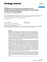
Fig. 2. The miniature mobile robot Khepera
®
.
algorithms from one robot to another is not a
difficult problem.
2. Nevertheless, to work with a real robot is largely
preferable to use simulations as far as, e.g., dealing
with sensor imperfections or real time constraints
is concerned.
3. Finally it is clear that the easiness to build and
modify the environment of a mini robot is greatly
appreciable.
Khepera
®
has a circular shape featuring 55mm in
diameter (2r), 30 mm in height and 70 g in weight
[20]. Two wheels and two small Teflon balls support it.
The robot possesses eight infrared sensors, which are
composed of an emitter and an independent receiver.
These sensors (S0, S1,...,S7) are disposed in a
somewhat circular fashion around its body (Fig. 2) and
allow the measurement of distances in a short range
from about 1 to 5 cm. Its maximum linear speed is
about 40 mm/s.
The robot’s linear and angular speeds are sent from
a host computer via a serial link to an on-board chip,
which is based on a Motorola 68331 micro-controller.
The linear speeds of the right and left wheels are then
calculated.
In this study, we assume the following conditions:
• The robot moves on a flat ground.
• Inertial effects are neglected.
• The used mobile robot has the non-holonomic
characteristic but this later is not constraining.
• The robot moves without sliding and can be
localized when it finds itself in a locally known
scene [22].
Most of the experiments are done on both the real
and a simulated mobile robot. The simulator dedicated
to Khepera
®
has been written in C++ by Michel
[19] and runs on SUN Sparc station. The experimental
results deduced from the real and simulated mobile
robot are very near.
3. Navigation strategies in unknown environment
3.1. Principle
In a totally unknown environment, the navigation is
done completely in a reactive manner. So a classical
method such as the artificial potential fields [11] could
be used. But it is well known that this method suffers
from local minima problems leading to blocking sit-
uations. A solution has been proposed in a previous
work [14] based on an automatic tuning of attractive
and repulsive force coefficients due to fuzzy rules.
Nevertheless some oscillation problems remain in nar-
row environments and passageways, which are very
constraining for dedicated utilities indoor robotics.
The described approach (Fig. 1) here is largely
based on fuzzy inference systems (FISs) and inspired
from human behavior, which consists to reach the
free space while seeking the goal (strategy S1). This
allows avoiding local minima by reaching the mid-
dle of the available free space when the robot passes
through a cluttered environment [2]. But some failing
situations are yet encountered in the case on concave
obstacles. That is why coordination of S1 and another
elementary behavior of wall-following type including
the creation of transition sub-goals develop a second
strategy S2. As a matter of fact, the idea is to antic-
ipate in order to avoid a potential blocking situation
rather than to discover it and subsequently react. So,
an obstacle will be in fact qualified as concave if all
the used exteroceptive sensors give simultaneously
small measurements of distances, since, even if the
obstacle has not really a concave geometric shape, it is
preferable to trigger the S2 strategy instead of taking
the risk to fall in a blocking situation with S1 strategy.
To skirt the two sides of the wall, the detection of
a concave obstacle (Fig. 3) provokes the creation of
an intermediate sub-goal of transition “SG[i]” at the
point of detection and triggers the wall-following be-
havior to act, e.g., on the left side. If the robot goes
H. Maaref, C. Barret / Robotics and Autonomous Systems 38 (2002) 1–18 5
Fig. 3. Concave obstacle skirting.
away from the target and the distance of displacement
is greater than a threshold distance T; it turns back
to the intermediate sub-goal SG[i] previously memo-
rized, due to the strategy S1. Then, it skirts the obsta-
cle on the other side, with the same threshold distance
T. The wall-following ceases if the two following con-
ditions are filled:
• The three sensors measure big distances.
• The goal is in the right or in the left (depending
on the side of the obstacle followed by the robot)
quadrant with respect to the actual direction of the
robot.
The developed algorithm allows a robot with exte-
roceptive sensors to travel from any start point S to
any target point G in a cluttered environment without
any prior knowledge on the location of the obstacles.
3.2. On-line optimization of FISs for reactive
strategies
The reactive strategies of navigation (reaching a
collision-free space, goal-seeking and wall-following)
are completely based on sensory information. Two
Fig. 4. Learning architecture.
of them (reaching a collision-free space and wall-
following) are built due to self-tunable fuzzy inference
systems (STFISs) controlling the angular ω and lin-
ear v speeds of the mobile robot. The angular speed is
generated first at a given linear speed and, then after
convergence of this later structure, the control rules of
the linear velocity are deduced.
With respect to the use of a classical, manually
tuned FIS to build the reactive behaviors of the robot,
the STFIS has the following two main advantages:
• It avoids the manual tuning of the parameters of
the FIS that can be in some cases quite long and
cumbersome. Moreover, this manual tuning leads
inevitably to a sub-optimal behavior.
• It allows to cope exactly with the physical char-
acteristics of the robot. If either these characteris-
tics evolve with time or the robot is changed (or a
change from a simulator robot to a real one is car-
ried out), the controller will adapt automatically to
the new situation.
The structure of the FIS is as follows. The member-
ship function for the input values are triangular and
fixed. A min operator performs the conjunction of the
inputs and the conclusions of the rules are numeri-
cal values W
i
(so-called weights). They are optimized
through a learning process [1].
The shape of the used membership functions is tri-
angular and fixed in order to extract and represent eas-
ily the knowledge from the final results. So the output
value y (v or ω)isgivenby
y =
n
i=1
W
i
× α
i
n
i=1
α
i
,
where α
i
are the truth values of each fired rule.
The learning architecture is presented in Fig. 4.
This architecture is a simplified version of the “distal
6 H. Maaref, C. Barret / Robotics and Autonomous Systems 38 (2002) 1–18
control” method proposed by Jordan and Rumelhart
[9] for neuro-control. In the original method, two neu-
ral networks are used: one for modeling the plant and
another for the controller. In fact, as pointed by Jordan
and Rumelhart it is not necessary to work with an ac-
curate model of the plant to obtain an efficient con-
trol. Saerens [26] and Renders [24] have shown that
the model network can be successfully approximated
by the sign of the terms of the Jacobian matrix of
the plant (in the assumption that these signs are fixed
on the working space, which is valid for a lot of real
systems). These results have been extended by substi-
tuting to the neural controller a fuzzy controller with
adaptive parameters [5], leading to the very simple
architecture as in Fig. 4 for single input single output
(SISO) systems.
The learning is entirely done on-line on the
actual robot. The table of rules (weights W
i
) is initially
empty. The robot acquires by its sensors the distances
to the environment, calculates the error to be back
propagated, updates the triggered rules in real time,
begins to move and so on, etc. The weights of the
table of decision are then adjusted locally and pro-
gressively. As the learning progresses, the mobile is
more and more able to cope with new situations.
The back-propagation training technique [25]
updates weights according to:
W(k + 1) = W(k)+ η
−∂J
∂W
,
where k is the training iteration, J is the cost function
used in the learning algorithm, η is the learning rate
and W (k) = W(k)− W(k − 1).
If the classical quadratic error is used as a cost
function, J =
1
2
ε
2
where ε depends on the task; the
back-propagation minimizes effectively the value of
J, leaning rapidly to a good reactive navigation. But,
if the learning is prolonged, the weights increase con-
tinuously with time and, progressively, the quality of
the control decreases. To overcome this difficulty, a
technique known as “weight decay” in classification
methods [6] and having a strong relation with ridge
regression and regularization theory [3] is used. So
a second term is included in the cost function that
becomes
J =
1
2
ε
2
+ λ
W
2
i
,
where λ is a coefficient proportional to α
i
/
α
i
.It
is chosen so that the output value does not exceed
the maximum angular speed of each wheel of the
robot (1.58 rad/s). By applying this method, a satura-
tion of the growth of the weights is obtained without
any degradation of the residual quadratic error and
the quality of the control is maintained even under
prolonged learning.
3.3. Avoidance of convex obstacles
This navigator is built by fusing two elementary
behaviors: a self-tunable fuzzy controller to reach the
middle of the free space and a crisp one to track the
current sub-goal.
3.3.1. Reaching the middle of the collision-free
space behavior
When the vehicle is moving towards the target and
the sensors detect an obstacle, an avoiding strategy is
necessary. The method consists of reaching the middle
of a collision-free space. This behavior is obtained by
means of an STFIS.
The input variables are respectively the normalized
measured distance on the right (R), on the left (L) and
in front (F) such as
R
n
=
R
R + L
,L
n
=
L
R + L
,F
n
=
F
σ
,
where front data F = min(S0, S7); right data R =
min(S6, S7); left data L = min(S1, S2) and σ is a
distance beyond which the obstacles are not taken into
account. Due to this normalization, the universes of
discourse evolved automatically with the sensor data
(Fig. 5).
The shape of the membership function is triangular
and the sum of the membership degrees for each vari-
able is always equal to 1. The universes of discourse
are normalized between 0 and 1.
For this behavior and to generate first the control
rules for the angular speed ω
a
, the error used in the
cost function is given by ε
ω
= Y −
1
2
(Y + F
n
) where
Y is either R
n
or L
n
. After a few rounds at a constant
linear speed on a learning track, the navigation of the
robot is satisfying.
The weights of the controller converge to the values
given in Table 1, where the linguistic labels for the in-
puts are defined as: Z (zero), S (small), M (medium),
H. Maaref, C. Barret / Robotics and Autonomous Systems 38 (2002) 1–18 7
Fig. 5. Evolution of the universe of discourse with the width of
the environment.
B (big) and VB (very big). These numerical values
could be eventually translated in symbolic values to
verify the logical meaning of the rules. We can assign
to them a linguistic interpretation by substituting the
symbolic concept PB (positive big) for the values
greater than 0.7, PS (positive small) for the values
between 0.2 and 0.7, Z (approximately zero) for the
values between −0.2 and 0.2, NS (negative small) for
the values between −0.2 and −0.7, and NB (negative
big) for the values lesser than −0.7. We obtain the
linguistic table for the angular speed from Table 2. It
is interesting to compare this later with a table written
Table 1
Angular speed coefficient rules
Table 2
Linguistic table for the angular speed
empirically from experience of a human driver, and
following the very usual diagonal structure known as
McVicar–Whelan’s [17] controller (Table 3). We can
observe that the two linguistic sets of rules are very
near. Only three cases (noted with ∗) are different
and they differ from only one linguistic concept (PS
instead of PB and Z instead of PS and NS). So, we
can claim that the extracted rules are quite logical and
coherent. Moreover, the use of STFISs allows the op-
timization of the controller with respect to the actual
characteristics of the robot. This means that the rough
and manual tuning of the parameters of the fuzzy con-
troller is replaced by a fine local automatic tuning and
Table 3
Linguistic table deduced by human expertise