MATERIALS SELECTION DESKBOOK pot
Bạn đang xem bản rút gọn của tài liệu. Xem và tải ngay bản đầy đủ của tài liệu tại đây (2.92 MB, 195 trang )
MATERIALS
SELECTION
DESKBOOK
by
Nicholas
P.
Cheremisinoff, Ph.D.
NOYES PUBLICATIONS
Westwood,
New
Jersey,
U.S.A.
Copyright
6
19%
by
Noyes Publications
No part
of
this
book
may
be
reproduced
a
utilized in
any
form
or
by any means, electronic
01
mechanical,
including photocopying, recording
01
by
any informa-
tion
storage and retrieval system, without
permission
in writing
from
the Publisher.
Library
of
Congress Catalog Card Number: 96-10911
Printed
in
the
United States
ISBN
0-8155-1400-X
Published in
the
United States
of
America
by
Noyes Publications
369
Fairview Avenue
Westwood,
New Jersey
07675
10
9
8
7
6
5
4
3
2
1
hirary
of
Congress Cataloging-in-Publication Data
Cheremisinoff,
Nicholas
P.
Materials selection deskbook
I
by
Nicholas
P.
Cheremisinoff.
Includes bibliographical
references.
1.
Materials Handbooks,
manuals,
etc.
I.
Title.
p.
an.
ISBN
0-8155-1400-X
TA404.8.C48 1996
66Cr.282 &20
96-10911
CIP
ABOUT
THE
AUTHOR
Nicholas
P.
Cheremisinoff
is
a private consultant to industry,
academia, and government. He has nearly twenty years of
industry and applied research experience
in
elastomers,
synthetic fuels, petrochemicals manufacturing, and environ-
mental control.
A
chemical engineer by trade, he has authored
over
100
engineering textbooks and has contributed extensively
to the industrial press, He
is
currently working for the United
States Agency for International Development in Eastern
Ukraine, where he is managing the Industrial Waste Manage-
ment Project.
Dr.
Cheremisinoff received his
B.S.,
M.S.,
and
Ph.D. degrees from Clarkson College of Technology.
V
NOTICE
To
the best of our knowledge the information in this pub-
lication is accurate; however, the Publisher does not assume
any responsibility or liability for the accuracy or completeness
of,
or
consequences arising from, such information. This book
is
intended for informational purposes only. Mention
of
trade
names or commercial products does not constitute endorsement
or recommendation for use by the Publisher. Final determ-
ination of the suitability of any information or product for use
contemplated by any user, and the manner of that use, is the
sole responsibility of the user. We recommend that anyone
in-
tending to rely on any recommendation of materials or pro-
cedures mentioned in this publication should satisfy himself as
to such suitability, and that he can meet
all
applicable safety
and health standards.
viii
The chemical and allied industries employ a multitude of unit
operations in product manufacturing. Both chemicals and physical
mechanisms are employed in these operations, ranging from simple
bulk handling and preparation of chemical feedstocks to complex
chemical reactions in the presence
of
heat and or mass transfer.
These operations require application of scientific and engineering
principles to ensure efficient, safe and economical process
operations.
To
meet these objectives, process equipment must
perform intended functions under actual operating conditions and do
so
in a continuous and reliable manner. Equipment must have the
characteristics of mechanical reliability, which includes strength,
rigidity, durability and tightness. In addition, it must be designed at
an optimized ratio of capital investment to service life.
This book is designed as a handy desk reference covering
fundamental engineering principles of project planning schemes and
layout, corrosion principles and materials properties of engineering
importance. It is intended as a general source of typical materials
property data, useful for first pass materials selection in process
design problems.
This book is based upon seminars given by the author during the
1980s.
With the recent addition
of
material relating to elastomers
and plastics, this book has been brought up-to-date.
Nicholas
P.
Cheremisinoff
vii
LIST
OF
FIGURES
1.1
1.2
2.1
2.2
2.3
2.4
2.5
2.6
2.7
2.8
3.1
3.2
3.3
3.4
3.5
3.6
3.7
Simplified flow diagram of activities in planning and
4
Allowable stress for different materials
11
Comparison of corrosion rates of zinc and steel in various
parts of the world
37
Examples of poor and proper connections of dissimilar metals
39
Example of a corrosion-resistant steel insert used in an aluminum
casting
40
Encapsulation
of
exposed metal connections
40
Gasket insertion between pipe flanges for sealing purposes and to
minimize galvanic corrosion between dissimilar piping metals
41
Examples of minimizing galvanic corrosion when piping
penetrates partitions and bulkheads
43
Poor and good designs for heat exchanger inlets
45
Poor and good designs for vessel drainage
45
Liquid-level gauge for an ammonia tank
54
Effect
of
temperature on corrosion rates of steels in crude oil
containing sulfur
66
Operating limits for steels in atmospheres containing hydrogen
66
Effect of temperature
on
the tensile strength of copper:
(A)
effect of annealing on strength and ductility;
(B)
hardened high conductivity copper
80
Effect of sulfuric acid on aluminum
92
Effect of nitric acid on stainless steel and aluminum
92
implementing process and plant design projects
Typical glass sight gauges
53
Xlll
LIST
OF
TABLES
1.1
1.2
1.3
1.4
1.5
2.1
2.2
2.3
2.4
2.5
3.1
3.2
3.3
3.4
3.5
3.6
3.7
3.8
3.9
3.10
3.11
Major items in operating guidelines planning
5
Common equipment symbols and letter codes
7
Typical instrument codes and examples
9
mange ratings for different materials
10
Typical flange pressure-temperature data
11
Parameters
to
analyze in materials selection
22
Fabrication parameters to analyze in materials selection
24
General properties of the corrosion resistance of metals to
various chemicals
27
General properties of the corrosion resistance
of
nonmetals to
various chemicals
31
Corrosion rates of steel and zinc panels exposed for
two
years
35
Typical mechanical properties of various types of cast iron
55
Typical data showing the effect of strength on gray iron
castings
563
Properties of white iron
56
58
Properties of flake graphite-grade cast irons
58
Maximum working stresses for various grades
of
cast iron
up to 600OC
61
Properties of spheroidal graphite-grade cast irons
Rods and electrodes for fusion-welding cast iron
61
Applications of low-carbon, low-alloy steels
64
Comparison of mild and low-alloy quenched and tempered
steels
65
Alloying effects that improve creep properties
67
AISI
classifications of
wrought
stainless and heat-resisting
steels (based on
AISI
type
numbers)
69
xiv
List of Tables
xv
3.12
3.13
3.14
3.15
3.16
3.17
3.18
3.19
3.20
3.21
3.22
3.23
3.24
3.25
3.26
3.27
3.28
3.29
3.30
3.31
3.32
3.33
3.34
3.35
3.36
3.37
3.39
3.40
3.41
3.42
3.43
3.44
3.45
3.46
3.47
3.48
3.49
3.50
B.l
Examples
of
precipitation hardening stainless steels
72
Various grades of copper
78
Mechanical properties vs temperature for copper
79
Mechanical properties vs low temperature for copper
79
Compositions
of
ferrite/austenite stainless steels
72
Classification used for copper alloys in the
U.S.
77
Properties of common brasses
82
Properties of tin bronzes and gunmetals
82
Mechanical properties of annealed cupro-nickel alloys
83
Standard
U.S.
leads 84
Mechanical properties
of
sheet lead
84
Mechanical properties
of
annealed lead vs temperature
84
Maximum stresses in pipe wall of lead alloys
85
Fatigue-strength data of lead alloys
85
Mechanical properties of aluminum
87
Mechanical properties of aluminum annealed at 37OOC
87
Tensile and compression allowable stresses for mild aluminum
(annealed) vs metal operating temperature
87
Effect of purity on the properties of aluminum
88
Typical properties of fully annealed nonheat-treatable
aluminum alloys
89
Effect of heat treatment on heat-treatable aluminum alloys
89
Various aluminum casting alloys 91
Aluminum
alloys
recommended for cryogenic applications
91
Properties of titanium. tantalum and zirconium
93
Mechanical properties of titanium and alloys
94
Effect of elevated temperatures on strength
of
titanium and
alloys
95
Comparative corrosion resistance
of tantalum and platinum
97
Properties of carbon and graphite
101
Chemical resistance of bedding and jointing cements
103
General properties and uses
of
thermoplastic materials
105
Mechanical properties
of thermoplastics
111
Hydrostatic design pressures for thermoplastic pipe for
temperatures up to 130°C
112
Effect
of
density on polyethylene polymers
112
Effects of degree of crystallinity and molecular weight
113
Properties of different nylons
116
Properties
of
different engineering plastics
117
Various properties of fiberglass resins
119
Various filler materials and their property contributions
to
plastics
121
Chemical resistance of epoxy resin coatings
124
Properties of important plastics and elastomers
162
mi List of Tables
B.2
B.3
B.4
B.5
B.6
B.7
B.8
B.9
B.10
B.ll
B.12
B.13
B.14
B.15
B.16
B.17
B.18
Terminology and properties of important elastomers
166
Synthesis and features of hydrogenated diene-diene
copolymers
168
Synthesis and features of hydrogenated aromatic-diene
Hydrogenation of functional diene polymers
170
Properties of liquid polysulfide polymers
171
Properties of arc0 ply bd R-45
HT
urethane composition
172
Properties of Cll3N-expoxy resin compositions
173
Properties of unfilled thermoplastic compositions
174
True stress at break of selected melt-mixed rubber-
Properties of various
types
of elastomer compositions
175
Nonextended polymers with unsaturated center block
176
Some commercial macroglycols that have been used to make
TPU
elastomers 177
TPU
product comparison chart
178
Physical properties of
1.
2-polybutadiene
180
Chemical and oil resistance of silicone rubber
183
Summary of solid
EP
and
EPDM
worldwide products
184
copolymers
169
plastic blends
175
Applications
and
features of
1,
2-polybutadiene
181
CONTENTS
AND
SUBJECT
INDEX
1
.
OVERALL PROCESS
SYSTEM
DESIGN
1
1.1
Introduction
1
1.2
Planning Projects and Equipment Design
2
Equipment and Instrumentation Codes
6
1.4
Vessel Codes and Flange Ratings
10
References
12
13
2
.
DESIGN AND CORROSION
13
2.1
Introduction
13
Types
of Corrosion
13
23
Materials
Evaluation
and Selection
18
2.4
Design
Guidelines
36
2.5
Glossary of Corrosion Terms
46
References
50
2.2
3
.
PROPERTIES AND SELECTION
OF
MATERIALS
51
General Properties and Selection Criteria
51
Properties of Cast Irons
53
3.2.1 Gray Cast Iron
55
3.2.2 White Cast
Iron
56
3.2.3 Malleable Cast Irons
56
3.2.4
Nodular
Cast
Iron
57
3.2.5 Austenitic Cast Iron
57
Application Requirements
of
Cast Irons
57
3.3.1 Abrasion Resistance
57
3.3.2 Corrosion Resistance
57
3.3.3 Temperature Resistance
60
3.1
3.2
33
ix
x Contents and Subject Index
3.3.4 Welding
Cast
Iron
60
Properties of Steels
61
3.4.1 Low Carbon Steels (Mild Steel)
62
3.4.2 Corrosion Resistance
63
3.4.3 Heat Resistance
63
3.4.4 Low Temperatures
63
3.4.5 High-Carbon Steels
63
3.4.6 Low-Carbon. Low-Alloy Steels
64
3.4.7 Mechanical Properties
64
3.4.8 Corrosion Resistance
64
3.4.9
Oxidation Resistance and Creep Strength
65
3.4.10 Low-Temperature Ductility
67
3.4.11 High-Carbon. Low-Alloy Steels
67
3.5
Properties of High-Alloy Steels
67
3.5.1
3.5.2 Medium Carbon Martensitic: 13-17% Chromium
3.5.3
3.5.4 Chromium/Nickel Austenitic Steels (300 Series)
68
3.5.5
Precipitation Hardening Stainless Steels
71
3.5.6
Chromium/NickeliFerrite/Austenite
Steels
72
3.5.7 Maraging Steels
73
Applications
of
High-Alloy Steels
73
3.6.1 Oxidation Resistance
74
3.6.2
3.6.3
Mechanical Properties at Low Temperatures
74
Corrosion-Resistant Nickel and Nickel Alloys
74
3.7.1 NickeVCopper (Alloy 400)
75
3.7.2 NickeVMolybdenum
75
3.7.3
Nickel/Molybdenum/Chromium
75
3.7.4
Nickel/Chromium/Molybdenum/Iron
75
3.7.5
NickeVChromium/Molybdenum/Copper
76
3.7.6 NickeVSilicon
76
3.8
Heat-Resistant Nickel Alloys
76
3.8.1
NickeVChromium
76
3.8.2 Nickel/Chromium/Iron
76
Copper and Copper Alloys
77
3.9.2 Tin Bronzes
81
Aluminum and Manganese
Bronzes
81
3.9.4 Silicon Bronzes
81
3.9.5
Cupro-Nickels
83
3.4
Chromium Steels (400 Series), Low-Carbon
Ferritic (Type 405): 12-13% Chromium
68
(Types 403. 410, 414. 416. 420. 431. 440)
68
(Types 430 and
446)
68
Medium Carbon Ferritic: 17-30% Chromium
3.6
Mechanical Properties at Elevated Temperatures
74
3.7
3.9
3.9.1 Brasses
79
3.9.3
Contents and Subject Index xi
3.9.6 Corrosion Resistance
83
3.10 Mechanical Properties
of
Lead and Lead Alloys
83
3.10.1 Corrosion Resistance
86
3.11 Aluminum and Aluminum Alloys
86
3.11.1
Aluminum Alloy Compositions
88
Aluminum Purity
88
Manganese Alloys
88
3.11.4 Heat-Treatable Alloys
89
3.11.5
Casting Alloys
90
3.11.6 Temperature Effects
90
3.11.7
Corrosion Resistance
90
3.11.8 OrganicAcids
91
3.12 Miscellaneous Precious Metals 93
3.12.1 Titanium
94
3.12.2 Tantalum
95
3.12.3 Zirconium
96
3.12.4 Precious Metals
97
3.12.5 Silver
97
3.12.6 Gold
98
3.12.7 Platinum
98
3.13 Metallic Coatings
98
3.13.1
Electrodeposition
98
3.13.2 Dip Coating
99
3.11.2 Aluminum of Commercial 99% Minimum
3.11.3
Nonheat-Treatable Magnesium and
3.13.3
Sprayed Coatings
99
3.13.4 Diffusion Coatings
99
3.14 Carbon, Graphite and Glass
100
3.14.2 Glass
101
3.15 Cements, Bricks and
Tiles
102
3.15.1
Cements
102
3.15.2 Bricks and Tiles
102
3.16 Plastic and Thermoplastic Materials
104
3.16.1
Polyolefins
104
3.16.2 Polyvinyl Chloride (€'VC)
114
3.16.5
Chlorinated PVC (CPVC)
114
3.14.1 Carbon and Graphite
100
3.16.3
Rigid PVC (UPVC)
114
3.16.4 High-Impact PVC
114
3.16.6
Plastic PVC
115
3.16.7
Acrylonitrile-Butadiene-Styrene
(ABS)
115
3.16.8
Fluorinated Plastics
115
3.16.9
Polyvinyl Fluoride
(€'vF)
115
3.16.10
Acrylics
116
xii Contents and Subject Index
3.16.11 Chlorinated Polyether
116
3.16.12 Nylon (Polyamide)
116
3.16.13 Miscellaneous Engineering Plastics
117
3.16.14 Acetal Resin
117
3.16.15 Polycarbonate
118
3.16.16 Polyphenylene Oxide
118
3.16.17 Polysulfone
118
3.17 Thermosetting Plastics
118
3.17.1 Phenolic Resins
119
3.17.2 Polyester Resins
119
3.17.3 Epoxy Resins
120
3.17.4 Furane Resins
120
3.17.5 Rubber Linings
121
3.18 Organic Coatings and Paints
123
3.19 Glossary of Fabrication and Plastics Terms
123
Nomenclature
141
References
141
APPENDIX A: GLOSSARY OF PLASTICS AND ENGINEERING
TERMS
145
APPENDIX
B:
GENERAL PROPERTIES AND DATA ON
ELAfXOMERS AND PLASTICS
161
1.
OVERALL PROCESS SYSTEM DESIGN
1.1
INTRODUCTION
The chemical process industries
(CPI),
petroleum and allied industries
apply physical as well as chemical methods to the conversion
of
raw feed-
stock materials into salable products. Because of the diversity of products,
process conditions and requirements, equipment design is often unique, or
case specific. The prime requirement
of
any piece of equipment is that it
performs the function for which it was designed under the intended process
operating conditions, and do
so
in a continuous and reliable manner. Equip-
ment must have mechanical reliability, which
is
characterized by strength,
rigidness, steadiness, durability and tightness. Any one
or
combination of
these characteristics may be needed for a particular piece of equipment.
The cost
of
equipment determines the capital investment for a process
operation. However, there is no direct relationship to profits. That is, more
expensive equipment may mean better quality, more durability and, hence,
longer service and maintenance factors. These characteristics can produce
higher operating efficiencies, fewer consumption coefficients and operational
expenses and,
thus,
fewer net production costs. The net cost of production
characterizes the perfection rate of the total technological process and
reflects the influences
of
design indices. Therefore, it is possible to compare
different pieces of equipment when they are used in the manufacture
of
these same products.
The desirable operating characteristics of equipment include simplicity,
convenience and
low
cost of maintenance; simplicity, convenience and low
cost
of
assembly and disassembly; convenience in replacing worn
or
damaged
components; ability to control during operation and test before permanent
installation; continuous operation and steady-state processing of materials
without excessive noise, vibration
or
upset conditions; a minimum of per-
sonnel for its operation; and, finally, safe operation. Low maintenance often
1
2
Materials Selection Deskbook
is associated with more complex designs as well as cost. Automation of
production is the most complete solution to problems associated with inain-
taining steady operation, easy maintenance and
a
minimum of operating
personnel. The addition of control devices must be considered as part of the
overall design and a factor that adds to the capital investment of
the
project.
Increased automation through
the
use of controls increases the degree of
sophistication in equipment design but lowers operational expenditures
while increasing production quality. The use of automatic devices influences
the form and dimensional proportions of the equipment as well as imposing
additional constraints on the design.
It
is justified by increased production
efficiencies and added security during normal and emergency operations.
Design practices often are neglected in engineering curricula. In fact,
most textbooks stress conceptual design fundamentals and leave the detailed
design principles to job experience and training. Consequently, equipment
design is often treated as an art rather than as an exact science that applies
rigorous engineering principles.
This
deficiency exists not only in many
engineering undergraduate curricula, but also in the industrial published
sector in that few texts present detailed design practices and guidelines. It is
the intent of the authors to
fill
this void, at least in part, by organizing
standard industrial design practices for equipment used throughout the CPI
and other major industries. This work will take the form
of
a series of
textbooks that provide detailed design and calculation procedures
for
sizing
and selecting equipment. We
shall
depart from the standard unit operations
textbooks, of which there are several classical works, by not stressing theory.
Rather, we
will
concentrate
on
specific design practices, computational
methods and working formulas. Hence, we hope the reader of principal
interest
will
be the practicing engineer.
This first volume presents fundamental design principles that may be
applied to
all
equipment. Emphasis is placed on process system peripherals,
particularly vessels and their associated components. Design principles for
all
types of vessels, and selection, sizing and design criteria for piping system
components are presented. Because practices rather than theory are stressed,
only
the final working formulas are presented; further, since we intend this
to
be a designer’s guide, numerous example problems are included through-
out the book.
The first chapter provides an overview
of
process design strategies.
Fundamental definitions and a brief review
of
preparing process
flow
plans
are included.
1.2.
PLANNING PROJECTS AND EQUIPMENT DESIGN
There are numerous stages of activities that must be conducted before an
actual process, plant or even small-scale pilot system reaches its operational
Overall
Process
System
Design
3
stage. Figure 1.1 is a simplified flow diagram illustrating some of the major
activities and their normal sequence. From the initial idea the engineer is
directed to prepare a preliminary design basis. This includes a rough flow
plan, a review
of
the potential hazards of the process and an assimilation of
all
available technical, economic and socioeconomic information and data.
At this stage of
a
project often the engineer
or
engineers are not the final
equipment designers, but merely play the devil’s advocate, by establishing
the equipment requirements. Dialog established between the conceptual
design engineer and the process designer results in an initial process flow
plan. From the flow plan, a preliminary cost estimate is prepared, many
times by a different engineer whose expertise is cost estimating. Once
management approval is received, the design engineer’s work begins. In the
initial stages the design engineer will help prepare a preliminary engineering
flow plan, select the site and establish safety requirements.
This
initial project stage is often considered a “predesign” period, which
constitutes the basis of the conceptual design. Usually a collection
of
indi-
viduals are involved in discussions and planning. The cast of characters
includes the project engineer, who oversees the entire project, the design
engineer (with whom we are most concerned), safety engineer, environmental
engineer and, perhaps, a representative from management and additional
support personnel.
Once the overall process has been designed conceptually, a more detailed
engineering flow plan is prepared. This flow plan serves two purposes;
(1)
to
document the logic behind the process operation, and
(2)
to identify in
detail major process equipment, including all control devices. A complete
flow plan also will identify potential hazards and their consequences, in
addition
to
how they are handled. After the environmental and safety engi-
neers have reviewed all potential hazards related
to
handling toxic materials,
noise, radiation, etc., recommendations are outlined for safe and standard
handling and disposal practices. These recommendations often affect the
overall system design, resulting in revised plans.
The next stage is the actual construction of the unit according
to
the
revised plans. By now, the design engineer is totally involved and has selected,
sized and designed most
of
the equipment and process piping, based
(hopefully) on the standard practices outlined in this book. During the
actual construction phase, the design engineer will list and review the plans
with the project engineer.
At the completion of the unit
or
system construction, a prestartup review
is
conducted
by
the designer and
his
support personnel.
This
should include
a review of all operating, as well as emergency and shutdown, procedures.
The prestartup review normally involves the following personnel in addition
to the designer: project engineer, trained operating personnel, operations
foreman, the company environmental engineer, the division and company
safety engineers and representatives
from
management.
At
this point, any
4
Materials Selection
Deskbook
Overall
Process
System
Design
5
additional changes
or
recommendations to the process design are made.
Major process revisions may be requested by the operations foreman, project
engineers, design engineer, safety and environmental coordinators and/or
plant operating personnel. Table
1.1
summarizes major items that are con-
sidered in the operating procedures planning.
The project planning activities may be much more complex than illustrated
Table
1.1.
Major
Items in Operating Guidelines Planning
PURPOSE OF PROCESS OR OPERATION
0
General Discussion of Process
What will be done (brief summary)
Chemistry involved
Major unit operations
HdzdrdS involved-severity
Protective equipment-what, where, when
Area restrictions-what, where, when
Ventilation
0
Personnel Protection
0
Startup
Preparation and handling
Feedstocks
Catalysts
Equipment
0
Step-by-step Description
Flow plans
Sketches
Labelled parts of units
Position
of
valves, control settings, etc.
0
Sampling and Final Product Form
Description
of
equipment
Actions required
Step-by-step description
0
Shutdown Procedure
Flow plans
Sketches
Labelled parts
of
unit
Position of valves, control settings, etc.
0
Emergency Shutdown Procedure
Action required
Followup required
Emergency personnel/outside organizations
Description
Hazards or precautions
0
Product or Waste
Disposal
0
Unit Cleaning Procedures
6
Materials Selection
Deskbook
by the simple flow diagram of Figure
1.1.
This depends, of course, on the
magnitude
of
the project. Often, large complex system planning has numer-
ous checkpoints at various stages where a continuous review of technical and
revised economic forecasts is performed.
Also
not shown in this flow dia-
gram is the legal framework
for
obtaining construction and operating permits
as well
as
preparing the environmental impact statement and meeting
local,
state and federal regulations.
1.3.
EQUlPMENT AND LNSTRUMENTATION
CODES
Process and instrumentation flow diagrams (P
&
I
diagrams) essentially
define the control and operating logic behind a process as well as provide a
visual record to management and potential users. In addition, P
&
I
diagrams
are useful at various stages of a project’s development by providing:
0
0
0
0
0
the opportunity for safety analysis before construction begins;
a tabulation of equipment and instrumentation
for
cost estimating purposes;
guidelines
for
mechanics and construction personnel during the plant assembly
stage;
guidance in analyzing startup problems;
assistance in training operating personnel; and
assistance in solving daily operating and sometimes emergency problems.
P
&
I
diagrams contain four important pieces
of
information, namely,
all
vessels, valves and piping, along with a brief description and identifying
specifications of each;
all
sensors, instruments and control devices, along
with a brief description
of
each; the control logic used in the process; and,
finally, additional references where more detailed information can be ob-
tained.
Information normally excluded from
P
&
I diagrams includes electrical
wiring (normally separate electrical diagrams must be consulted), nonprocess
equipment (e.g., hoist, support structures, foundations, etc.) and scale
drawings of individual components.
There are basically two parts to the diagram: the first provides a schematic
of equipment and the second details the instrumentation and control devices.
The P
&
I
diagram provides a clear picture of what each piece of equipment
is, including identifying specifications, the size of various equipment,
materials of construction, pressure vessel numbers and ratings, and drawing
numbers. Equipment and instrumentation are defined in terms
of
a code
consisting of symbols, letters and a numbering system. That is, each piece
of equipment is assigned its own symbol; a letter is used to identify each
type of equipment and to assist
in
clarifying symbols, and numbers are used
to
identify individually each piece of equipment within a given equipment
type. Table
1.2
illustrates common equipment symbols and corresponding
letter codes.
Overall
Process
System
Design
7
Table 1.2. Common Equipment
Symbols
and
Letter
Codes
~ ~~
Equipment
Symbol Code Information Needs
Conrrol
valve
Piping
Valves
Centrifugal
Pump
Rotameter
Reactor
Filter
Back Pressure
Regulator
cv
P
a
__c=l_
LOADING
BAS
-&
Tracing
Spring-Loaded
Relief Valve
Size, maximum flowrate,
pressure drop
Material, size, wall
thickness
Type: ball
(B),
globe
(G),
needle
(N),
etc.
Inlet/outlet pressure,
flowrate
R Tube, float, body,
maximum flowrate
R
Pressure vessel
no.,
drawing no., size
FIL Pore size
Range
of
gauge and
loading source
Shown
on
vessel with
power pack and control
signal
Type: steam
(S)/
electric (E)
Relief pressure, orifice
size
8
Materials
Selection
Deskbook
When denoting instrumentation it is important that definitions be under-
stood clearly. Terms
for
instruments and controls most often included on
P
&
I
diagrams are given below:
Instrument Loop-A combination
of
one
or
more interconnected instru-
ments arranged
to
measure
or
control a process variable.
Final Control Element-A device that directly changes the value
of
the
variable used to control a process condition.
Transducer (Converter) A device that receives
a
signal from one power
source and outputs a proportional signal in another power system. A trans-
ducer can act as a primary element, transmitter
or
other device.
Fail Closed (usually normally closed)-An instrument that will
go
to the
closed position
on
loss
of
power (pneumatic, electric, etc.).
Fail Open (usually normally open)-An instrument that
will
go
to the open
position on loss
of
power (pneumatic, electric, etc.).
Fail Safe-An instrument that on loss of power (pneumatic, electric, etc.)
wd1 go to a position that cannot create a safety hazard.
Process Variable-A physical property or condition in a fluid
or
system.
Instrument-A device that measures or controls a variable.
Local-An instrument located on the equipment.
Remote-An instrument located away from the equipment (normally a
Primary Element-A device that measures a process variable.
Indicator-A device that measures a process variable and displays that
variable at the point of measurement.
Transmitter-A device that senses a process variable through a primary
element and puts out a signal proportional
to
that variable
to
a remotely
located instrument.
Controller-A device that varies its output automatically in response to
changes in a measured process variable
to
maintain that variable at a desired
value (setpoint).
Instrumentation normally is denoted by a circle in which the variable
being measured or controlled
is
denoted by an appropriate letter symbol
inside the circle. When the control device is to be located remotely, the
circle is divided in half with a horizontal line. Table
1.3
gives various
instrumentation symbols and corresponding letter codes. The specific
op-
erating details and selection criteria for various process instrumentation are
not discussed in this book. The reader is referred to earlier works by
Cheremisinoff
[
1,2]
for discussions on essential control and measurement
instrumentation.
Piping normally is denoted by solid lines. Piping lines on the P
&
I
diagram
should be accompanied by the following identifying information:
control cabinet).
1.
line
number,
2.
nominal pipe
size
and
wall
thickness,
Overall
Process
System
Design
9
Table 1.3. Typical lnstrument Codes and Examples
General Symbols
0
Instrument process
piping
lnstrument air lines
Electrical leads
Capillary tubing
Locally mounted
instrument
(single service)
Locally mounted
transmitter
Board-mounted
transmitter
Diaphragm
motor
valve
$3
Electrically operated
valvc (solenoid
or
motor)
Piston-opcrated valve
(hydraulic or
pneumatic)
3-way body
for
any valve
Safety (relief) valve
Manually operated
control valve
~ ~~
Temperature Symbols
Temperature
recording controller
Temperature well
Temperature indicator
'd
Pressure Symbols
Pressure alarm
Pressure controller
(blind type)
Prcssurc indicator
(locally mounted)
Pressure recorder
(board mounted)
Flow Symbols
-
1-
Flow indicator,
I:low recorder
b
differential type
($
10
Materials Selection Deskbook
3.
origin and termination,
4.
design temperature and pressure,
5. specified corrosion allowance,
6.
7.
insulation type and thickness,
8.
9.
winterizing or process protection requirements (i.e., heat tracing via steam or
electric),
test pressure (indicate hydrostatic
or
pneumatic), and
piping flexibility range (e.g., the maximum
or
minimum operating temperature).
1.4.
VESSEL CODES AND FLANGE RATINGS
In
this first volume we shall direct much of our attention to vessel design.
In
the United States, the primary standard for pressure vessel design is that
of
the American Society
of
Mechanical Engineers (ASME).
(In
subsequent
chapters information
on
European codes for vessels shall be reviewed.) The
ASME code is essentially a legal requirement. It provides the minimum
construction requirements
for
the design, fabrication, inspection and certifi-
cation of pressure vessels. The ASME code does
not
cover: (1) vessels
subject
to
federal control;
(2)
certain water and hot water tanks,
(3)
vessels
with
an
internal operating pressure not exceeding
15
psig with
no
limitation
on
size; and
(4)
vessels having an inside diameter not exceeding
6
inches
with
no
limitation
on
pressure.
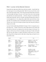
Flange ratings are also specified by the ASME. Table 1.4 gives the various
flange ratings in terms
of
the strength of materials, as based
on
ASME
standards. Table
1.5
gives data
on
flange pressure-temperature ratings.
Finally, Figure
1.2
gives data on allowable stress at different temperatures
for carbon steel pipe and
304
stainless steel plate.
All pressure vessels must pass appropriate hydrostatic testing before
approval for service.
For
safety reasons, hydrostatic pressure testing is
almost always recommended over a pneumatic test. The recommended
Table
1.4.
Flange Ratings for Different Materials
Strength of Materials
~~
Carbon Steel Stainless Steel
150
Ib
@
500°F
@
500°F
300
Ib
600
Ib
900
Ib
1500
Ib
2500
Ib
@
850°F
@
1000°F
I
Overall Process
System
Design
11
Table
1.5.
Typical Flange Pressure-Temperature Data
Carbon Steel
304
SS
”F
150
psia
300
psia
150
psia
300
psia
IO0
275 720 275 615
200 240
700
240 550
300 210 680 210 495
400
180 665 180 450
500 150 625 150 410
600
130
555
130
380
700 110 470 110 355
800
92
3
65 92
3
30
900 70 225 70 310
1000 40 85
40 300
1100
255
1200
155
- -
-
-
-
-
204300
I
I I
I
I
I
-
C.S.
SA
106
Gr.A
Y
W
-I
m
a
3
5,000
-
s
a
J
0
I
I
I
I
I
I
0
2
4
6
8
10
12
OF/
100
Figure
1.2.
Allowable stress
for
different materials.
hydrostatic test is typically
150%
of the temperature corrected design.
The
pneumatic test is typically
125%
of design, as recommended by
ASME.
A
“proof-test” is used when calculations are not possible.
This
requires at least
twice the maximum allowable pressure and employs a brittle coat
on
the
vessel to indicate overstress.
12
Materials
Selection
Deskbook
REFERENCES
1.
Cheremisinoff,
N.
P.
Applied
Iq'luid /+'low
Mtvzsurcnient
(New
York: Marcel
2.
Cheremisinoff,
N.
P.
Process
1,eivl
Instrumentation and Cotitrol
(New
Dekker, Inc.,
1979).
York: Marcel Dekker,
Inc.,
1981).