Engineering rock mechanics: part 2 IIlustrative worked examples.CHILE Continuous, Homogeneous, pdf
Bạn đang xem bản rút gọn của tài liệu. Xem và tải ngay bản đầy đủ của tài liệu tại đây (14.13 MB, 530 trang )
Engineering rock
mechanics: part 2
IIlustrative worked examples
CHILE Continuous, Homogeneous, Isotropic and Linearly Elastic
DIANE Discontinuous, Inhomogeneous, Anisotropic and Not-Elastic
Frontispiece
Part of the concrete foundation beneath a multi-storey car park
on the Island of Jersey in the Channel Islands
Engineering rock
mechanics: part 2
Illustrative worked examples
John R Harrison
Senior Lecturer in Engineering Rock Mechanics
Imperial College of Science, Technology and Medicine
University of London, UK
and
John A. Hudson FREng
Professor o Engineering Rock Mechanics
f
Imperial College o Science, Technology and Medicine
f
University of London, UK
Pergamon
UK
Elsevier Science Ltd, The Boulevard, Longford Lane, Kidlington,
Oxford OX5 lGB, UK
USA
Elsevier Science Inc., 665 Avenue of the Americas, New York,
NY 10010, USA
JAPAN
Elsevier Science Japan, Higashi Azabu 1-chome Building 4F,
1-9-15, Higashi Azabu, Minato-ku, Tokyo 106, Japan
Copyright @ 2000 J.P. Harrison and J.A. Hudson
All Rights Resewed. No part of this publicationmay be
reproduced, stored in a retrieval system or transmitted in any
form or by any means: electronic, electrostatic, magnetic tape,
mechanical, photocopying, recording or otherwise, without
permissionin writing from the publishers.
First edition 2000
Library of Congress Cataloging-in Publication Data
A catalog record from the Library of Congress has been applied
for.
British library Cataloguing in Publication Data
A catalog record from the British Library has been applied for.
ISBN: 0 08 043010 4
Disclaimer
No responsibility is assumed by the Authors or Publisher for any
injury and/or damage to persons or property as a matter of
products liability, negligence or otherwise, or from any use or operation of any methods, products, instructions or ideas contained
in the material herein.
Printed in The Netherlands
For all our past, present andhture students and colleagues
at Imperial College
About the authors
Dr J.P. Harrison
John Harrison graduated in civil engineering from Imperial College,
University of London, and then worked for some years in the civil
engineering industry for both contracting and consulting organisations.
This was interspersed by studies leading to a Master’s degree, also from
Imperial College, in Engineering Rock Mechanics. He was appointed
Lecturer in Engineering Rock Mechanics at Imperial College in 1986,
then obtained his Ph.D. in 1993, and became Senior Lecturer in 1996.
He currently directs undergraduate and postgraduate teaching of engineering rock mechanics within the Huxley School of the Environment,
Earth Sciences and Engineering. His personal research interests are in the
characterisation and behaviour of discontinuous rock masses, an extension of his earlier Ph.D. work at Imperial College on novel mathematical
methods applied to the analysis of discontinuity geometry.
Professor J.A. Hudson FREng
John Hudson graduated in 1965 from the Heriot-Watt University, U.K.
and obtained his Ph.D. at the University of Minnesota, U.S.A. He has
spent his professional career in engineering rock mechanics - as it
applies to civil, mining and environmental engineering -in consulting,
research, teaching and publishing and has been awarded the D.Sc.
degree for his contributions to the subject. In addition to authoring many
scientific papers, he edited the 1993 five-volume ”Comprehensive Rock
Engineering” compendium, and currently edits the International Journal
of Rock Mechanics and Mining Sciences.
From 1983 to the present, Professor Hudson has been affiliated with
Imperial College as Reader and Professor. He is also a Principal of Rock
Engineering Consultants, actively engaged in applying engineering rock
mechanics principles and techniques to relevant engineering practice
worldwide. In 1998, he was elected as a Fellow of the Royal Academy of
Engineering in the U.K.
Contents
Preface
Units and Symbols
xi
xiii
Part A Illustrative worked examples -Questions and
answers
1 Introduction
1.1 The subject of engineering rock mechanics
1.2 Questions and answers: introduction
1.3 Additional points
2 Geological setting
2.1 Rock masses
2.2 Questions and answers: geological setting
2.3 Additional points
13
13
19
26
3 Stress
27
3.1 Understanding stress
3.2 Questions and answers: stress
3.3 Additional points
27
30
37
4 In s i t u rock stress
39
39
42
56
4.1 The nature of i situ rock stress
n
4.2 Questions and answers: in situ rock stress
4.3 Additional points
5 Strain and the theory of elasticity
5.1 Stress and strain are both tensor quantities
5.2 Questions and answers: strain and the theory of elasticity
5.3 Additional points
57
57
6 Intact rock defonnability, strength and failure
71
6.1 Intact rock
6.2 Questions and answers: intact rock
6.3 Additional points
71
74
87
60
68
viii
Contents
89
7 Fractures and hemisphericalprojection
7.1 Natural, pre-existing fractures
7.2 Questions and answers: fractures and hemispherical
projection
7.3 Additional points
100
115
8 Rock masses: deformability, strength and failure
8.1 The nature of rock masses
8.2 Questions and answers: rock masses
8.3 Additional points
117
117
122
138
9 Permeability
9.1 Permeability of intact rock and rock masses
9.2 Question and answers: permeability
9.3 Additional points
141
141
144
157
89
10 Anisotropy and inhomogeneity
10.1 Rock masses: order and disorder
10.2 Questions and answers: anisotropy and inhomogeneity
10.3 Additional points
159
159
161
172
11 Testing techniques
11.1 Rock properties
11.2 Questions and answers: testing techniques
11.3 Additional points
175
175
176
192
12 Rock mass classification
193
12.1 Rock mass parameters and classificationschemes
12.2 Questions and answers: rock mass classification
12.3 Additional points
193
194
212
13 Rock dynamics and time dependency
13.1 Strain rates
13.2 Questions and answers: rock dynamics and time
dependency
13.3 Additional points
215
215
14 Rock mechanics interactions and rock engineering systems
14.1 Interactions
14.2 Questions and answers: rock mechanics interactions and rock
engineering systems
14.3 Additional points
231
231
15 Excavation principles
15.1 Rock excavation
15.2 Questions and answers: excavation principles
15.3 Additional points
247
247
250
262
16 Rock reinforcement and rock support
265
265
16.1 The stabilization system
16.2 Questions and answers: rock reinforcement and rock
support
16.3 Additional points
217
228
234
244
267
281
Contents
ix
17 Foundation and slope instability mechanisms
17.1 Near-surface instability
17.2 Question and answers: foundation and slope instability
mechanisms
17.3 Additional points
288
309
18 Design of surface excavations
18.1 The project objective
18.2 Questions and answers: design of surface excavations
18.3 Additional points
311
311
314
337
19 Underground excavation instability mechanisms
19.1 Underground instability
19.2 Questions and answers: underground excavation instability
mechanisms
19.3 Additional points
339
339
343
369
20 Design of underground excavations
20.1 The project objective
20.2 Question and answers: design of underground excavations
20.3 Additional points
373
373
375
397
285
285
Part B: Questions only
The Questions in Part A are reproduced here without the answersfor those
who wish to attempt the questions without the answers being visible.
Questions 1 1 1 5 introduction
.-.
401
.-.0
Questions 2 1 2 1 geological setting
403
Questions 3 1 3 1 stress
.-.0
407
.-.0
Questions 4 1 4 1 in situ rock stress
409
Questions 5 1 5 1 strain and the theory of elasticity
.-.0
413
.-.0
Questions 6 1 6 1 intact rock
417
Questions 7.1-7.10 fractures and hemispherical projection
421
Questions 8 1 8 1 rock masses
.-.0
425
Questions 9.1-9.10 permeability
431
Questions 10.1-10.10 anisotropy and inhomogeneity
437
Questions 11.1-11.10 testing techniques
441
Questions 12.1-12.10 rock mass classification
447
Questions 13.1-13.10 rock dynamics and time dependency
451
Questions 14.1-14.10 rock mechanics interactions and rock
engineering systems
45s
Questions 15.1-15.10 excavation principles
459
Questions 16.1-16.10 rock reinforcement and rock support
465
x
Contents
Questions 17.1-17.10 foundation and slope instability
mechanisms
469
Questions 18.1-18.10 design of surface excavations
473
Questions 19.1-19.10 underground excavation instability
mechanisms
477
Questions 20.1-20.10 design of underground excavations
481
References
487
Appendix A. 3-D stress cube model
491
Appendix B Hemispherical projection sheet
493
Appendix C Rock mass classification tables -R M R and Q
495
Index
503
Preface
This book can be used as a 'standalone' textbook or as a complement to our first book, Engineering Ruck Mechanics: An infroductiun to the
Principles. It contains illustrative worked examples of engineering rock
mechanics in action as the subject applies to civil, mining, petroleum
and environmental engineering. The book covers the necessary understanding and the key techniques supporting the rock engineering design
of structural foundations, dams, rock slopes, wellbores, tunnels, caverns,
hydroelectric schemes, mines.
In our first book, we presented the basic principles of engineering rock
mechanics with strong emphasis on understanding the fundamental concepts. Because it is also important to consider the principles in action,
to have practice in applying them, and to be able to link the principles
with specific engineering problems, we prepared this second book containing the illustrative worked examples. We have adopted a question
and worked answer presentation:the question and answer sets have been
collated into twenty chapters which match the subject matter of our first
book -Chapters 1-13 on rock mechanics principles and Chapters 14-20
on applications in rock engineering. Part A of this book can be read as a
narrative consisting of sequencesof text, questionsand answers, or in Part
B the same questions can be tackled without the answers being visible.
Chapters 1-20 have the same format:
Section 1. Introductory aide-memoire to the chapter subject.
Section 2. Questions with worked answers that illustrate the principles
of the rock mechanics subject and the associated rock engineering design issues.
Section 3. Additional points, often reinforcing the most important aspects of the subject.
Not only will the question and answer sets enhance understanding of the rock mechanics principles, but they will also provide the
reader with fluency in dealing with the concepts explained in our first
book. Moreover, the question sets give examples of the procedures often
encountered in practice. In this way, confidence in tackling practical
problems will be developed, together with an improved creative abil-
xii
Preface
ity for approaching all rock engineering problems. It is important to
realize that engineering flair is only possible if the basic principles and
techniques are understood and implementable.
There are three appendices. Appendix A contains a 3-D stress cube
cut-out which can be copied and made into a model as an aide-memoire.
Appendix B contains a hemispherical projection sheet which can be
copied and used especially for the questions in Chapter 7. Appendix C
contains l W R and Q rock mass classification tables.
Thus, the book serves as an illustrated guide and explanation of the
key rock mechanics principles and techniques for students, teachers,
researchers, clients, consulting engineers and contractors. We mentioned
in the Preface to our first book that rock engineering occurs deep in the
earth, high in the mountains and often in the world’s wildest places.
We engineer with rocks as we create structures, extract the primary
raw materials for mankind and harness the forces of nature. It is the
romance and the passion associated with rock engineering that has led
us to try to communicate some of this excitement. ’Personal experience
is everything’. So, we hope that you will be able to experience some of
the science, art and romance of the subject by understanding and then
implementing the principles and techniques described in this book.
The book contains the tutorial exercises for students who take the
integrated engineering rock mechanics course at Imperial College, University of London, plus many extra examples to ensure that the book is
comprehensive and is suitable for all reader purposes and backgrounds,
whether academic or practical. Because the tutorial exercises have been
incrementally refined, extended and corrected over the years by the rock
mechanics staff and students at Imperial College, it is not possible to
coherently acknowledge the origin of all individual questions. However,
we express our profound appreciation to everyone who has contributed
in different ways to the questions and answers contained herein.
The authors are especially grateful to their wives, Gwen Harrison and
Carol Hudson, for all their support and for helping to improve the style
and accuracy of the text. The final version is, of course, our responsibility.
If there is anything that you do not understand in the following pages, it
is our fault.
J.P Harrison and J.A.Hudson
T.H. Huxley School of Environment, Earth Sciences and Engineering,
Imperial College of Science, Technology and Medicine,
University of London, SW7 2BP, UK
Our companion first book ”Engineering Rock Mechanics An Introduction to the Principles”, also published by Pergamon,
Elsevier Science, will be referred to throughout as “ERM 1”.
Units and symbols
Units
There are two reasons why it is important to understand and use
engineering rock mechanics units correctly:
engineering rock mechanics calculations used for rock engineering
design should be numerically correct; and
to use engineering rock mechanics properly, an understanding of units
is necessary.
We have used standard symbols and the SI (International System) of
units. There are seven base units in the SI system: length, mass, time,
electric current, thermodynamic temperature, amount of substance and
luminous intensity. These base units are dimensionally independent.
Base unifs
For engineering rock mechanics, we consider just the length, mass and
time base units.
Base
Quantity
quantity
Length
symbol
I
Mass
Time
m
t
Nameof
SIunit
SIunit
Dimensions
of unit
metre
kilogram
second
m
kg
L
M
T
s
xiv
Units and symbols
Derived units
From the three base units, all the other mechanical units are derived.
Some of the main derived units are listed below.
Derived
quantity
Quantity Narneof
symbol
Area
A
Volume
V
Density
P
Velocity
2,
Acceleration a
W
Weight
Force
F
P
Pressure
E
Energy
SIdt
Dimensions
of unit
m2
m3
kg m-3
m s-I
m s-*
m kg s - ~
m kg s-'
N m-2,m-l kg s-'
N m, m2 kg s-'
L2
L3
SIunit
newton, N
newton, N
pascal, Pa
joule, J
L-3M
LT-'
LT-'
LMT-2
LMT-2
L-'MT-'
L*MT-*
The name of the SI unit, e.g. newton, is written with an initial lower case
letter, and its abbreviation, e.g. N, is written with an initial upper case
letter.
Note that force is defined through the relation: force = mass x acceleration. A newton, N, is the force necessary to accelerate a one kilogram
mass at a rate of one metre per second per second. This is clear for dynamic circumstances but the force definition also applies to the concept
and the units used in the static case. When a static force exists, the force
between two stationary objects, the units of force are still m kg s2
with
dimensions Lh4T2 because of the definition of force. Thus, other derived
and
units, such as Young's modulus, have units of m-l kg s - ~ dimensions L-'MT-2, despite the fact that there may be no time dependency in
their definition.
The most common prefixes used for decimal multiples of units in
engineering rock mechanics are
10-6
10-3
i
v
106
micro
milli
m
kilo
k
mega
giga
M
G
u
109
Symbols used in this book1
The main symbols used in this book are listed below, together with
the name of the quantity they represent, the SI unit name (where
appropriate), the SI unit and the dimensions of the unit. Other symbols
and abbreviations introduced for a specific question and answer have
been defined 'locally' in those questions and answers.
'We follow the recommendations i Quantities, Units and Symbols prepared by the
n
Symbols Committee of the Royal Society, 1975,54pp.
'The term 'dimensions' is used here to mean the complete listing of the dimensions
and exponents, as in L-'MT-', rather than just the Lh4T components, or just their
exponents, -1,l, -2.
Symbols used in this book
Symbol
(Y
B
BW
Y
Y
--a a a
Quantity
Nameof
SI unit
angle, specifically dip
direction of a plane or
trend of a line
angle, specifically dip
angle of a plane or plunge
of a line
orientation angle of plane
of weakness
shear strain
unit weight
partial differential operator
x
v
SIunit
Dimensions
of unit
radian, rad;
degree, deg
1
kg s - ~
m-2
L
O
L-~MT-~
m
L
1
L
O
1
L-'
pascal, Pa
pascal, Pa
pascal, Pa
pascal, Pa
m-'
1
m2 s-I
kg m-3
N m-2, m-l
N m-2, m-I
N m-2,
N m-2, m-I
pascal, Pa
pascal, Pa
N m-2, m-' kg ss2 L-' M T - 2
N m-2, m-I kg s-* L-1MT-2
radian, rad;
degree, deg
radian, rad;
degree, deg
ax' ay' az
Al, Sx, Sy, Sz increment of distance,
displacement
linear strain
angle
fracture frequency
Poisson's ratio
kinematic viscosity
density
stress tensor
normal stress
principal stress
uniaxial compressive
strength
principal horizontal stress
uniaxial tensile strength
variance
shear stress
angle of friction
radian, rad;
degree, deg
-
L~T-~
L-3M
kg s - ~ L-'MY2
kg s - ~ L-'MT-2
kg s - ~ L-' m2
kg s-' L-'MY2
pascal, Pa
N m-2, m-I kg s - ~ L-LMT-2
radian, rad;
degree, deg
radian, rad;
friction angle of plane of
degree, deg
weakness
area
m2
L2
L-' M T - ~
pascal, Pa
cohesion
N m-2, m-I kg
hydraulic conductivity of a
L T-I
m
fracture
pascal, Pa
Young's modulus
fracture aperture
pascal, Pa
elastic modulus of rock
mass
newton, N
force
pascal, Pa
shear modulus
pascal, Pa
shear modulus of rock
mass
geological strength index
value
hydraulic gradient
radian, rad;
asperity angle
degree, deg
stress invariants
constant of proportionality
number of events
m2
L*
coeffiaent of permeability
Units and symbols
xvi
Symbol
Quantity
K
hydraulic conductivity
stiffness
fracture normal stiffness,
fracture shear stiffness,
length
Cartesian axes
coefficient in Hoek-Brown
strength criterion
number in sample
pressure
breakdown pressure, shut-in
pressure
point load index value
flow rate
rock mass quality rating
radius
rock mass rating value
rock quality designation, YO
rock quality designation for
threshold value r
elastic compliance
elastic compliance matrix
coefficient in Hoek-Brown
strength criterion
sample standard deviation
threshold value for RQD
thickness
displacement
unconfined compressive
strength
displacement
weight
Cartesian axes
mean fracture spacing
sample mean
depth
standard normal variable
K
knr ks
L
1, m, n
m
N
P
PB, ps
PL
Q
Q
r
M R
RQD
RQDt
S
S
S
S
t
I
U
ucs
V
W
x , yt z
xbar
Xbar
Z
2
Name of
SI unit
SI unit
Dimensions
of unit
m s-l
kg s - ~
m-2 kg s - ~
LT-'
m
L
MT-2
L-2MT-2
pascal, Pa
pascal, Pa
N m-2, m-' kg
L-'MT-2
N m-2, m-' kg s - ~ L-'MT-2
pascal, Pa
N m-2, m-' kg s - ~ L-'MT-2
L3T-'
m3 s-l
m
L
lacsap, Pa-'
lacsap, Pa-'
N-' m2,m kg-' s2 LM-'T2
N-' m2,m kg-' s2 LM-'T2
pascal, Pa
m
m
m
N m-2, m-' kg s - ~
L
L
L
L-'MT-*
m
kg m
L
LMT-~
m
L
m
L
The convention for writing symbols is as follows.
Symbols for tensor quantities should be in sans serif bold italic form,
e.g. S.
n
Symbols for vector quantities should be i bold italic form, e.g.F.
Symbols in Latin or Greek should be in italic form, e.g.x.
Part A:
IIIustrat ive worked
examples
Questions
and Answers
-
7
Introduction
1.1 The subject of engineering rock mechanics
The term engineering rock mechanics is used to describe the engineering application of rock mechanics to civil, mining, petroleum and
environmental engineering circumstances. The term mechanics, means
the study of the equilibrium and motion of bodies, which includes statics
and dynamics l . Thus, rock mechanics is the study of mechanics applied
to rock and rock masses. ’Engineering rock mechanics’ is this study
within an engineering context, rather than in the context of natural processes that occur in the Earth‘s crust, such as folding and faulting. The
term rock engineering refers to the process of engineering with rock,
and especially to creating structures on or in rock masses, such as slopes
alongside roads and railways, dam foundations, shafts, tunnels, caverns,
mines, and petroleum wellbores.
There is an important distinction between ’rock mechanics’ and ’rock
engineering’. When ‘rock mechanics’ is studied in isolation, there is
no specific engineering objective. The potential collapse of a rock mass
is neither good nor bad: it is just a mechanical fact. However, if the
collapsing rock mass is in the roof of a civil engineering cavern, there
is an adverse engineering connotation. Conversely, if the collapsing rock
mass is part of a block caving system in mining (where the rock mass
is intended to fail), there is a beneficial engineering connotation. In the
civil engineering case, the integrity of the cavern is maintained if the
rock mass in the roof does not collapse. In the mining engineering case,
the integrity of the mining operation is maintained if the rock mass does
collapse.
Hence, rock engineering applies a subjective element to rock mechanics, because of the engineering objective. The significance of the rock
mass behaviour lies in the eye and brain of the engineer, not in the
mechanics.
I It is not always realized that the term ‘mechanics’ includes ‘dynamics’,but a book
title such as ’River Mechanics’ is correct. S m l r y ’rock dynamics’, the topic of Chapter
iial,
13, is part of ‘rock mechanics’.
4
Introduction
‘Rock Mechanics’
‘Engineering Rock Mechanics’ and
‘Rock Engineering’ Design
Figure 1 1 The distinction between ‘rock mechanics’ itself (a) and engineering applications
.
of rock mechanics (b). In (a), F1...Fnare the boundary forces caused by rock weight and
current tectonic activity. In (b) a tunnel is being constructed in a rock mass.
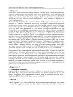
The distinction between ’rock mechanics’ and ’rock engineering’ illustrated in Fig. 1.1is highlighted further in Fig. 1.2 which shows part of
the concrete foundation illustrated in the Frontispiece. ‘Rock mechanics’
involves characterizing the intact rock strength and the geometry and
mechanical properties of the natural fractures of the rock mass. These
studies, together with other aspects of the rock mass properties such as
rock stiffness and permeability, can be studied without reference to a
specific engineering function. When the studies take on a generic engineering direction, such as the structural analysis of foundations, we are in
the realm of ’engineeringrock mechanics’. This is analogous to the term
engineering geology in which geology is studied, not in its entirety but
those aspects which are relevant to engineering.
‘Rock engineering’ is concerned with specific engineering circumstances: in this case (Fig. 1.2), the consequences of loading the rock
mass via the concrete support. How much load will the rock foundation
support under these conditions? Will the support load cause the rock to
Figure 1 2 Portion of Frontispiece photograph illustrating loading of discontinuous rock
.
mass by the concrete support of a multi-storey car park, Jersey, UK.
Questions and answers: introduction
5
slip on the pre-existing fractures? Is the stiffness of the concrete support
a significant parameter in these deliberations? If the rock mass is to be
reinforced with rockbolts, where should these be installed? How many
rockbolts should there be? At what orientation should they be installed?
All these issues are highlighted by the photograph in Fig. 1.2.
Above the Frontispiece photograph, there are two acronyms:
CHILE -Continuous, Homogeneous, Isotropic and Linearly Elastic;
DIANE -Discontinuous, Inhomogeneous, Anisotropic and Not-Elastic.
These refer to two ways of thinking about and modelling the rock mass.
In the CHILE case, we assume an ideal type of material which is not
fractured, or if it is fractured the fracturing can be incorporated in the
elastic continuum properties. In the DIANE case, the nature of the real
rock mass is recognized and we model accordingly, still often making
gross approximations.Rock mechanics started with the CHILE approach
and has now developed techniques to enable the DIANE approach to
be implemented. It is evident from Fig. 1.2 that a DIANE approach is
essential for this problem, using information about the orientation and
strength of the rock fractures. However, both approaches have their
advantages and disadvantages, and the wise rock engineer will utilize
each to maximal advantage according to the circumstances.
Modelling for rock mechanics and rock engineering should be based
on ensuring that the relevant mechanisms and the governing parameters
relating to the problem in hand have been identified. Then, the choice of
modelling technique is based on the information required, e.g. ensuring
an adequate foundation as illustrated in Fig. 1.2.
Accordingly, and to enhance an engineer’s skills, the question sets in
Chapters 1-13 are designed to improve familiarity with the main rock
mechanics topics and the techniques associated with the topics, such as
stress analysis and hemispherical projection methods. In Chapter 14,
we emphasize the importance of considering the ’rock mass-engineering
structure’ as a complete system. Finally, in Chapters 15-20, the question
sets are related to specific engineeringactivitiesand design requirements.
You can read the question and answer text directly in each of the
chapters, as in Section 1.2 following, or you can attempt the quesat
tions first without seeing the answers, as in Question Set 1 in P r B.
Whichever method you choose for reading the book, we recommend
that you read the introductory text for each chapter topic before tackling
the questions.
1.2 Questions and answers: introduction
In this introductory chapter, there are five questions concerned with the
nature of engineering rock mechanics. In all subsequent chapters there
are ten questions.
Q l . 1 Define the following terms:
rock mechanics;
0
engineering rock mechanics;
6
lntroduction
rock engineering;
structural geology;
engineering geology;
soil mechanics;
geotechnicalengineering.
A1.l Rockmechanics is the study of the statics and dynamics of rocks
and rock masses.
Engineering rock mechanics is the study of the statics and dynamics of
rocks and rock masses in anticipation of the results being applied to
engineering.
Rock engineering involves engineering with rocks, especially the construction of structures on or in rock masses, and includes the design
process.
Structural geology deals with the description and analysis of the structure
of rock masses.
EngineePing geology is the study of geology in anticipation of the results
being applied to engineering.
Soil mechanics is the study of the statics and dynamics of soils.
Geutechnicul engineering is the process of engineering with rocks and/or
soils’
.
41.2 Explain the fundamental purposes of excavation in civil engineering, mining engineering, and petroleum engineering.
C v l engineering. It is the rock opening, the space resulting from
ii
excavation, that is required in civil engineering - for railways, roads,
water transport, storage and disposal o different materials - often
f
designed for an engineering life of 120 years.
Mining engineering. It is the excavated rock itself that is required in
mining engineering, plus the ability to transport the rock. Underground
space is created when the rock is removed, e.g. the mine stopes in metal
mines; separate underground space is required to transport the mined
rock/ore to the surface. The design life of mine openings can vary from a
few days (as in longwall coal mining), to some months or years, to many
years, depending on the mine design, methods, and requirements.
Petroleum engineering. Wellbores (deep boreholes) are used to extract
petroleum and so the excavated space is used for transport. The design
life of the wellbores is similar to the mining circumstances: it will depend
on the overall strategy and lifetime of the oil field. Note that, in contrast
to civil and mining engineering, environmental problems such as surface
subsidence and groundwater movement are not caused by the creation
of underground space per se, but by the removal of oil from the reservoir
rock where it is trapped.
A1.2
* In the 1990s,the International Society for Soil Mechanics and Foundation Engineering
changed its name to the International Society for Soil Mechanics and Geotechnical
Engineering. The International Society for Rock Mechanics considered a complementary
change to the InternationalSociety for Rock Mechanics and Geotechnical Engineeringbut
did not go ahead with the change.