Welding of Pipelines and Related Facilities pot
Bạn đang xem bản rút gọn của tài liệu. Xem và tải ngay bản đầy đủ của tài liệu tại đây (523.47 KB, 86 trang )
Welding of Pipelines and
Related Facilities
API STANDARD 1104
NINETEENTH EDITION, SEPTEMBER 1999
ERRATA 1, OCTOBER 31, 2001
Welding of Pipelines and
Related Facilities
Pipeline Segment
API STANDARD 1104
NINETEENTH EDITION, SEPTEMBER 1999
ERRATA 1, OCTOBER 31, 2001
SPECIAL NOTES
API publications necessarily address problems of a general nature. With respect to partic-
ular circumstances, local, state, and federal laws and regulations should be reviewed.
API is not undertaking to meet the duties of employers, manufacturers, or suppliers to
warn and properly train and equip their employees, and others exposed, concerning health
and safety risks and precautions, nor undertaking their obligations under local, state, or fed-
eral laws.
Information concerning safety and health risks and proper precautions with respect to par-
ticular materials and conditions should be obtained from the employer, the manufacturer or
supplier of that material, or the material safety data sheet.
Nothing contained in any API publication is to be construed as granting any right, by
implication or otherwise, for the manufacture, sale, or use of any method, apparatus, or prod-
uct covered by letters patent. Neither should anything contained in the publication be con-
strued as insuring anyone against liability for infringement of letters patent.
Generally, API standards are reviewed and revised, reafÞrmed, or withdrawn at least every
Þve years. Sometimes a one-time extension of up to two years will be added to this review
cycle. This publication will no longer be in effect Þve years after its publication date as an
operative API standard or, where an extension has been granted, upon republication. Status
of the publication can be ascertained from the API
Pipeline Segment [telephone (202) 682-
8000]. A catalog of API publications and materials is published annually and updated quar-
terly by API, 1220 L Street, N.W., Washington, D.C. 20005.
This document was produced under API standardization procedures that ensure appropri-
ate notiÞcation and participation in the developmental process and is designated as an API
standard. Questions concerning the interpretation of the content of this standard or com-
ments and questions concerning the procedures under which this standard was developed
should be directed in writing to the general manager of the Pipeline Segment, American
Petroleum Institute, 1220 L Street, N.W., Washington, D.C. 20005. Requests for permission
to reproduce or translate all or any part of the material published herein should also be
addressed to the general manager.
API standards are published to facilitate the broad availability of proven, sound engineer-
ing and operating practices. These standards are not intended to obviate the need for apply-
ing sound engineering judgment regarding when and where these standards should be
utilized. The formulation and publication of API standards is not intended in any way to
inhibit anyone from using any other practices.
Any manufacturer marking equipment or materials in conformance with the marking
requirements of an API standard is solely responsible for complying with all the applicable
requirements of that standard. API does not represent, warrant, or guarantee that such prod-
ucts do in fact conform to the applicable API standard.
All rights reserved. No part of this work may be reproduced, stored in a retrieval system, or
transmitted by any means, electronic, mechanical, photocopying, recording, or otherwise,
without prior written permission from the publisher. Contact the Publisher,
API Publishing Services, 1220 L Street, N.W., Washington, D.C. 20005.
Copyright © 1999 American Petroleum Institute
FOREWORD
This standard was prepared by a formulating committee that included representatives of
the American Petroleum Institute, the American Gas Association, the Pipe Line Contractors
Association, the American Welding Society, and the American Society for Nondestructive
Testing, as well as representatives of pipe manufacturers and individuals associated with
related industries.
The purpose of this standard is to present methods for the production of high-quality welds
through the use of qualiÞed welders using approved welding procedures, materials, and
equipment. Its purpose is also to present inspection methods to ensure the proper analysis of
welding quality through the use of qualiÞed technicians and approved methods and equip-
ment. It applies to both new construction and in-service welding.
The use of this standard is entirely voluntary and is intended to apply to welding of piping
used in the compression, pumping, and transmission of crude petroleum, petroleum prod-
ucts, fuel gases, carbon dioxide, and nitrogen and, where applicable, to distribution systems.
This standard represents the combined efforts of many engineers who are responsible for
the design, construction, and operation of oil and gas pipelines, and the committee apprecia-
tively acknowledges their wholehearted and valuable assistance.
From time to time, revisions of this standard will be necessary to keep current with tech-
nological developments. The committee is always anxious to improve this standard and will
give full consideration to all comments received.
An appeal of any API standards action by an interested party shall be directed to the API.
API publications may be used by anyone desiring to do so. Every effort has been made by
the Institute to assure the accuracy and reliability of the data contained in them; however, the
Institute makes no representation, warranty, or guarantee in connection with this publication
and hereby expressly disclaims any liability or responsibility for loss or damage resulting
from its use or for the violation of any federal, state, or municipal regulation with which this
publication may conßict.
Suggested revisions are invited and should be submitted to the general manager of
the Pipeline Segment, American Petroleum Institute, 1220 L Street, N.W., Washington, D.C.
20005.
ATTENTION USERS:
Portions of this standard have been changed from the previous edi-
tion. The locations of changes have been marked with a bar in the margin, as shown to the
left of this paragraph. In some cases, the changes are signiÞcant, while in other cases the
changes reßect minor editorial adjustments. The bar notations are provided as an aid to users
as to those parts of the standard that have been changed from the previous edition, but API
makes no warranty as to the accuracy of such bar notations.
iii
API-AGA JOINT COMMITTEE ON OIL AND
GAS PIPELINE FIELD WELDING PRACTICES
H. Charles Price, Chairman
George K. Hickox, Vice-Chairman
Frank R. Orr, Secretary
American Petroleum Institute
Donald Drake
Gary E. Merritt
David Noble
Gary Perkins
American Gas Association
Marshall L. Farley
Alan C. Holk
Frank R. Orr
Eugene L. Smith
American Society for Nondestructive Testing
David L. Culbertson
C. P. Woodruff, Jr.
Scott M. Metzger
William R. Tignor
American Welding Society
W. L. Ballis
George K. Hickox
Chuck Brashears
Robert R. Wright
National Electrical Manufacturers Association
Craig Dallman
Pipe Manufacturers
Frank M. Christensen
Murali D. Tumuluru
Martin A. Francis
James P. Snyder, II
Pipeline Contractors Association
Ralph Pendarvis
H. Charles Price
Don Thorn
Bill Marhofer
Members Emeritus
John K. McCarron
R. B. Gwin
M. Jordan Hunter
E. L. Von Rosenberg
Dale Wilson
iv
CONTENTS
Page
1 GENERAL. . . . . . . . . . . . . . . . . . . . . . . . . . . . . . . . . . . . . . . . . . . . . . . . . . . . . . . . . . . . 1
1.1 Scope. . . . . . . . . . . . . . . . . . . . . . . . . . . . . . . . . . . . . . . . . . . . . . . . . . . . . . . . . . . 1
2 REFERENCED PUBLICATIONS . . . . . . . . . . . . . . . . . . . . . . . . . . . . . . . . . . . . . . . . . 1
3 DEFINITION OF TERMS . . . . . . . . . . . . . . . . . . . . . . . . . . . . . . . . . . . . . . . . . . . . . . . 2
3.1 General . . . . . . . . . . . . . . . . . . . . . . . . . . . . . . . . . . . . . . . . . . . . . . . . . . . . . . . . . 2
3.2 DeÞnitions . . . . . . . . . . . . . . . . . . . . . . . . . . . . . . . . . . . . . . . . . . . . . . . . . . . . . . 2
4 SPECIFICATIONS . . . . . . . . . . . . . . . . . . . . . . . . . . . . . . . . . . . . . . . . . . . . . . . . . . . . . 2
4.1 Equipment. . . . . . . . . . . . . . . . . . . . . . . . . . . . . . . . . . . . . . . . . . . . . . . . . . . . . . . 2
4.2 Materials . . . . . . . . . . . . . . . . . . . . . . . . . . . . . . . . . . . . . . . . . . . . . . . . . . . . . . . . 2
5 QUALIFICATION OF WELDING PROCEDURES FOR WELDS CONTAINING
FILLER-METAL ADDITIVES . . . . . . . . . . . . . . . . . . . . . . . . . . . . . . . . . . . . . . . . . . . 3
5.1 Procedure QualiÞcation . . . . . . . . . . . . . . . . . . . . . . . . . . . . . . . . . . . . . . . . . . . . 3
5.2 Record. . . . . . . . . . . . . . . . . . . . . . . . . . . . . . . . . . . . . . . . . . . . . . . . . . . . . . . . . . 3
5.3 Procedure SpeciÞcation . . . . . . . . . . . . . . . . . . . . . . . . . . . . . . . . . . . . . . . . . . . . 3
5.4 Essential Variables . . . . . . . . . . . . . . . . . . . . . . . . . . . . . . . . . . . . . . . . . . . . . . . . 6
5.5 Welding of Test JointsÑButt Welds . . . . . . . . . . . . . . . . . . . . . . . . . . . . . . . . . . 7
5.6 Testing of Welded JointsÑButt Welds . . . . . . . . . . . . . . . . . . . . . . . . . . . . . . . . 8
5.7 Welding of Test JointsÑFillet Welds. . . . . . . . . . . . . . . . . . . . . . . . . . . . . . . . . 13
5.8 Testing of Welded JointsÑFillet Welds. . . . . . . . . . . . . . . . . . . . . . . . . . . . . . . 15
6 QUALIFICATION OF WELDERS . . . . . . . . . . . . . . . . . . . . . . . . . . . . . . . . . . . . . . . 15
6.1 General . . . . . . . . . . . . . . . . . . . . . . . . . . . . . . . . . . . . . . . . . . . . . . . . . . . . . . . . 15
6.2 Single QualiÞcation . . . . . . . . . . . . . . . . . . . . . . . . . . . . . . . . . . . . . . . . . . . . . . 15
6.3 Multiple QualiÞcation . . . . . . . . . . . . . . . . . . . . . . . . . . . . . . . . . . . . . . . . . . . . 16
6.4 Visual Examination . . . . . . . . . . . . . . . . . . . . . . . . . . . . . . . . . . . . . . . . . . . . . . 16
6.5 Destructive Testing . . . . . . . . . . . . . . . . . . . . . . . . . . . . . . . . . . . . . . . . . . . . . . . 18
6.6 RadiographyÑButt Welds Only . . . . . . . . . . . . . . . . . . . . . . . . . . . . . . . . . . . . 19
6.7 Retesting . . . . . . . . . . . . . . . . . . . . . . . . . . . . . . . . . . . . . . . . . . . . . . . . . . . . . . . 19
6.8 Records . . . . . . . . . . . . . . . . . . . . . . . . . . . . . . . . . . . . . . . . . . . . . . . . . . . . . . . . 19
7 DESIGN AND PREPARATION OF A JOINT FOR PRODUCTION WELDING. . 19
7.1 General . . . . . . . . . . . . . . . . . . . . . . . . . . . . . . . . . . . . . . . . . . . . . . . . . . . . . . . . 19
7.2 Alignment . . . . . . . . . . . . . . . . . . . . . . . . . . . . . . . . . . . . . . . . . . . . . . . . . . . . . . 19
7.3 Use of Lineup Clamp for Butt Welds. . . . . . . . . . . . . . . . . . . . . . . . . . . . . . . . . 19
7.4 Bevel . . . . . . . . . . . . . . . . . . . . . . . . . . . . . . . . . . . . . . . . . . . . . . . . . . . . . . . . . . 19
7.5 Weather Conditions . . . . . . . . . . . . . . . . . . . . . . . . . . . . . . . . . . . . . . . . . . . . . . 19
7.6 Clearance . . . . . . . . . . . . . . . . . . . . . . . . . . . . . . . . . . . . . . . . . . . . . . . . . . . . . . 19
7.7 Cleaning Between Beads . . . . . . . . . . . . . . . . . . . . . . . . . . . . . . . . . . . . . . . . . . 20
7.8 Position Welding. . . . . . . . . . . . . . . . . . . . . . . . . . . . . . . . . . . . . . . . . . . . . . . . . 20
7.9 Roll Welding . . . . . . . . . . . . . . . . . . . . . . . . . . . . . . . . . . . . . . . . . . . . . . . . . . . . 20
7.10 IdentiÞcation of Welds . . . . . . . . . . . . . . . . . . . . . . . . . . . . . . . . . . . . . . . . . . . . 20
7.11 Pre- and Post-Heat Treatment . . . . . . . . . . . . . . . . . . . . . . . . . . . . . . . . . . . . . . 20
8 INSPECTION AND TESTING OF PRODUCTION WELDS . . . . . . . . . . . . . . . . . . 20
8.1 Rights of Inspection . . . . . . . . . . . . . . . . . . . . . . . . . . . . . . . . . . . . . . . . . . . . . . 20
v
Page
8.2 Methods of Inspection . . . . . . . . . . . . . . . . . . . . . . . . . . . . . . . . . . . . . . . . . . . . 20
8.3 QualiÞcation of Inspection Personnel . . . . . . . . . . . . . . . . . . . . . . . . . . . . . . . . 20
8.4 CertiÞcation of Nondestructive Testing Personnel . . . . . . . . . . . . . . . . . . . . . . 21
9 ACCEPTANCE STANDARDS FOR NONDESTRUCTIVE TESTING. . . . . . . . . . 21
9.1 General . . . . . . . . . . . . . . . . . . . . . . . . . . . . . . . . . . . . . . . . . . . . . . . . . . . . . . . . 21
9.2 Rights of Rejection. . . . . . . . . . . . . . . . . . . . . . . . . . . . . . . . . . . . . . . . . . . . . . . 21
9.3 Radiographic Testing . . . . . . . . . . . . . . . . . . . . . . . . . . . . . . . . . . . . . . . . . . . . . 21
9.4 Magnetic Particle Testing. . . . . . . . . . . . . . . . . . . . . . . . . . . . . . . . . . . . . . . . . . 27
9.5 Liquid Penetrant Testing . . . . . . . . . . . . . . . . . . . . . . . . . . . . . . . . . . . . . . . . . . 27
9.6 Ultrasonic Testing. . . . . . . . . . . . . . . . . . . . . . . . . . . . . . . . . . . . . . . . . . . . . . . . 27
9.7 Visual Acceptance Standards for Undercutting . . . . . . . . . . . . . . . . . . . . . . . . . 28
10 REPAIR AND REMOVAL OF DEFECTS . . . . . . . . . . . . . . . . . . . . . . . . . . . . . . . . . 29
10.1 Authorization for Repair . . . . . . . . . . . . . . . . . . . . . . . . . . . . . . . . . . . . . . . . . . 29
10.2 Repair Procedure . . . . . . . . . . . . . . . . . . . . . . . . . . . . . . . . . . . . . . . . . . . . . . . . 29
10.3 Acceptance Criteria . . . . . . . . . . . . . . . . . . . . . . . . . . . . . . . . . . . . . . . . . . . . . . 29
10.4 Supervision . . . . . . . . . . . . . . . . . . . . . . . . . . . . . . . . . . . . . . . . . . . . . . . . . . . . . 29
10.5 Welder. . . . . . . . . . . . . . . . . . . . . . . . . . . . . . . . . . . . . . . . . . . . . . . . . . . . . . . . . 29
11 PROCEDURES FOR NONDESTRUCTIVE TESTING . . . . . . . . . . . . . . . . . . . . . . 29
11.1 Radiographic Test Methods . . . . . . . . . . . . . . . . . . . . . . . . . . . . . . . . . . . . . . . . 29
11.2 Magnetic Particle Test Method . . . . . . . . . . . . . . . . . . . . . . . . . . . . . . . . . . . . . 34
11.3 Liquid Penetrant Test Method . . . . . . . . . . . . . . . . . . . . . . . . . . . . . . . . . . . . . . 34
11.4 Ultrasonic Test Methods. . . . . . . . . . . . . . . . . . . . . . . . . . . . . . . . . . . . . . . . . . . 34
12 AUTOMATIC WELDING . . . . . . . . . . . . . . . . . . . . . . . . . . . . . . . . . . . . . . . . . . . . . . 37
12.1 Acceptable Processes . . . . . . . . . . . . . . . . . . . . . . . . . . . . . . . . . . . . . . . . . . . . . 37
12.2 Procedure QualiÞcation . . . . . . . . . . . . . . . . . . . . . . . . . . . . . . . . . . . . . . . . . . . 38
12.3 Record. . . . . . . . . . . . . . . . . . . . . . . . . . . . . . . . . . . . . . . . . . . . . . . . . . . . . . . . . 38
12.4 Procedure SpeciÞcation . . . . . . . . . . . . . . . . . . . . . . . . . . . . . . . . . . . . . . . . . . . 38
12.5 Essential Variables . . . . . . . . . . . . . . . . . . . . . . . . . . . . . . . . . . . . . . . . . . . . . . . 39
12.6 QualiÞcation of Welding Equipment and Operators . . . . . . . . . . . . . . . . . . . . . 40
12.7 Records of QualiÞed Operators . . . . . . . . . . . . . . . . . . . . . . . . . . . . . . . . . . . . . 40
12.8 Inspection and Testing of Production Welds . . . . . . . . . . . . . . . . . . . . . . . . . . . 40
12.9 Acceptance Standards for Nondestructive Testing . . . . . . . . . . . . . . . . . . . . . . 40
12.10 Repair and Removal of Defects . . . . . . . . . . . . . . . . . . . . . . . . . . . . . . . . . . . . . 40
12.11 Radiographic Testing . . . . . . . . . . . . . . . . . . . . . . . . . . . . . . . . . . . . . . . . . . . . . 40
13 AUTOMATIC WELDING WITHOUT FILLER-METAL ADDITIONS . . . . . . . . . 40
13.1 Acceptable Processes . . . . . . . . . . . . . . . . . . . . . . . . . . . . . . . . . . . . . . . . . . . . . 40
13.2 Procedure QualiÞcation . . . . . . . . . . . . . . . . . . . . . . . . . . . . . . . . . . . . . . . . . . . 40
13.3 Record. . . . . . . . . . . . . . . . . . . . . . . . . . . . . . . . . . . . . . . . . . . . . . . . . . . . . . . . . 46
13.4 Procedure SpeciÞcation . . . . . . . . . . . . . . . . . . . . . . . . . . . . . . . . . . . . . . . . . . . 46
13.5 Essential Variables . . . . . . . . . . . . . . . . . . . . . . . . . . . . . . . . . . . . . . . . . . . . . . . 46
13.6 QualiÞcation of Equipment and Operators . . . . . . . . . . . . . . . . . . . . . . . . . . . . 46
13.7 Records of QualiÞed Operators . . . . . . . . . . . . . . . . . . . . . . . . . . . . . . . . . . . . . 46
13.8 Quality Assurance of Production Welds . . . . . . . . . . . . . . . . . . . . . . . . . . . . . . 46
13.9 Acceptance Standards for Nondestructive Testing . . . . . . . . . . . . . . . . . . . . . . 47
13.10 Repair and Removal of Defects . . . . . . . . . . . . . . . . . . . . . . . . . . . . . . . . . . . . . 47
13.11 Radiographic Procedure . . . . . . . . . . . . . . . . . . . . . . . . . . . . . . . . . . . . . . . . . . . 47
vi
Page
APPENDIX A ALTERNATIVE ACCEPTANCE STANDARDS FOR
GIRTH WELDS . . . . . . . . . . . . . . . . . . . . . . . . . . . . . . . . . . . . . . . . . . . . 49
A.1 General . . . . . . . . . . . . . . . . . . . . . . . . . . . . . . . . . . . . . . . . . . . . . . . . . . . . . . . . 49
A.2 Additional Requirements for Stress Analysis . . . . . . . . . . . . . . . . . . . . . . . . . . 49
A.3 Welding Procedure . . . . . . . . . . . . . . . . . . . . . . . . . . . . . . . . . . . . . . . . . . . . . . . 50
A.4 QualiÞcation of Welders. . . . . . . . . . . . . . . . . . . . . . . . . . . . . . . . . . . . . . . . . . . 54
A.5 Inspection and Acceptable Limits . . . . . . . . . . . . . . . . . . . . . . . . . . . . . . . . . . . 54
A.6 Record. . . . . . . . . . . . . . . . . . . . . . . . . . . . . . . . . . . . . . . . . . . . . . . . . . . . . . . . . 55
A.7 Example . . . . . . . . . . . . . . . . . . . . . . . . . . . . . . . . . . . . . . . . . . . . . . . . . . . . . . . 55
A.8 Repairs . . . . . . . . . . . . . . . . . . . . . . . . . . . . . . . . . . . . . . . . . . . . . . . . . . . . . . . . 59
A.9 Nomenclature . . . . . . . . . . . . . . . . . . . . . . . . . . . . . . . . . . . . . . . . . . . . . . . . . . . 59
APPENDIX B IN-SERVICE WELDING . . . . . . . . . . . . . . . . . . . . . . . . . . . . . . . . . . . . 61
B.1 General . . . . . . . . . . . . . . . . . . . . . . . . . . . . . . . . . . . . . . . . . . . . . . . . . . . . . . . . 61
B.2 QualiÞcation of In-Service Welding Procedures . . . . . . . . . . . . . . . . . . . . . . . . 62
B.3 In-Service Welder QualiÞcation. . . . . . . . . . . . . . . . . . . . . . . . . . . . . . . . . . . . . 63
B.4 Suggested In-Service Welding Practices . . . . . . . . . . . . . . . . . . . . . . . . . . . . . . 64
B.5 Inspection and Testing of In-Service Welds. . . . . . . . . . . . . . . . . . . . . . . . . . . . 67
B.6 Standards of Acceptability: Nondestructive Testing (Including Visual) . . . . . . 67
B.7 Repair and Removal of Defects . . . . . . . . . . . . . . . . . . . . . . . . . . . . . . . . . . . . . 67
Figures
1 Sample Procedure SpeciÞcation Form . . . . . . . . . . . . . . . . . . . . . . . . . . . . . . . . . . 4
2 Sample Coupon Test Report . . . . . . . . . . . . . . . . . . . . . . . . . . . . . . . . . . . . . . . . . . 5
3 Location of Test Butt-Weld Specimens for Procedure QualiÞcation Test . . . . . . . 9
4 Tensile-Strength Test Specimen . . . . . . . . . . . . . . . . . . . . . . . . . . . . . . . . . . . . . . 10
5 Nick-Break Test Specimen . . . . . . . . . . . . . . . . . . . . . . . . . . . . . . . . . . . . . . . . . . 10
6 Root- and Face-Bend Test Specimen: Wall Thicknesses Less Than or Equal to
0.500 in. (12.7 mm) . . . . . . . . . . . . . . . . . . . . . . . . . . . . . . . . . . . . . . . . . . . . . . . . 11
7 Side-Bend Test Specimen: Wall Thicknesses Greater than 0.500 in.
(12.7 mm) . . . . . . . . . . . . . . . . . . . . . . . . . . . . . . . . . . . . . . . . . . . . . . . . . . . . . . . 12
8 Dimensioning of Imperfections in Exposed Weld Surfaces . . . . . . . . . . . . . . . . . 12
9 Jig for Guided-Bend Tests. . . . . . . . . . . . . . . . . . . . . . . . . . . . . . . . . . . . . . . . . . . 13
10 Location of Nick-Break Test Specimens: Fillet-Weld Procedure and Welder
QualiÞcation Test Welds . . . . . . . . . . . . . . . . . . . . . . . . . . . . . . . . . . . . . . . . . . . . 14
11 Location of Nick-Break Test Specimens: Fillet-Weld Procedure and Welder
QualiÞcation Test Welds, Including Size-to-Size, Branch-Connection Welder
QualiÞcation Test. . . . . . . . . . . . . . . . . . . . . . . . . . . . . . . . . . . . . . . . . . . . . . . . . . 14
12 Location of Test Butt-Weld Specimens for Welder QualiÞcation Test . . . . . . . . 17
13 Inadequate Penetration Without High-Low (IP). . . . . . . . . . . . . . . . . . . . . . . . . . 21
14 Inadequate Penetration Due to High-Low (IPD) . . . . . . . . . . . . . . . . . . . . . . . . . 23
15 Inadequate Cross Penetration (ICP) . . . . . . . . . . . . . . . . . . . . . . . . . . . . . . . . . . . 23
16 Incomplete Fusion at Root of Bead or Top of Joint (IF) . . . . . . . . . . . . . . . . . . . 23
17 Incomplete Fusion Due to Cold Lap (IFD). . . . . . . . . . . . . . . . . . . . . . . . . . . . . . 23
18 Internal Concavity (IC) . . . . . . . . . . . . . . . . . . . . . . . . . . . . . . . . . . . . . . . . . . . . . 23
19 Maximum Distribution of Gas Pockets: Wall Thicknesses Less Than or Equal to
0.500 in. (12.7 mm) . . . . . . . . . . . . . . . . . . . . . . . . . . . . . . . . . . . . . . . . . . . . . . . . 25
20 Maximum Distribution of Gas Pockets: Wall Thicknesses Greater Than
0.500 in. (12.7 mm) . . . . . . . . . . . . . . . . . . . . . . . . . . . . . . . . . . . . . . . . . . . . . . . . 26
21 Standard Penetrameter. . . . . . . . . . . . . . . . . . . . . . . . . . . . . . . . . . . . . . . . . . . . . . 32
22A Reference Block for Manual UT. . . . . . . . . . . . . . . . . . . . . . . . . . . . . . . . . . . . . . 36
22B Establishing Distance, Refracted Angle, and Velocity . . . . . . . . . . . . . . . . . . . . . 37
vii
Page
22C Transfer Procedure . . . . . . . . . . . . . . . . . . . . . . . . . . . . . . . . . . . . . . . . . . . . . . . . 37
23 Location of Test Butt-Weld Specimens for Flash-Weld Procedure
QualiÞcation Test: Outside Diameter Greater Than 18 in. (457 mm)
but Less Than or Equal to 24 in. (610 mm) . . . . . . . . . . . . . . . . . . . . . . . . . . . . . 42
24 Location of Test Butt-Weld Specimens for Flash-Weld Procedure
QualiÞcation Test: Outside Diameter Greater Than 24 in. (610 mm)
but Less Than or Equal to 30 in. (762 mm) . . . . . . . . . . . . . . . . . . . . . . . . . . . . . 43
25 Location of Test Butt-Weld Specimens for Flash-Weld Procedure
QualiÞcation Test: Outside Diameter Greater Than 30 in. (762 mm) . . . . . . . . . 44
26 Two-Inch Nick-Break Test Specimen . . . . . . . . . . . . . . . . . . . . . . . . . . . . . . . . . . 45
A-1 Location of CTOD Test Specimens . . . . . . . . . . . . . . . . . . . . . . . . . . . . . . . . . . . 51
A-2 Machining Objective for CTOD Test Specimen With Respect to Pipe Wall . . . . 52
A-3 Location of Notch for Weld-Metal Specimen. . . . . . . . . . . . . . . . . . . . . . . . . . . . 52
A-4 Location of Notch for Heat-Affected Zone Specimen . . . . . . . . . . . . . . . . . . . . . 52
A-5 Alternative Acceptance Criteria for Circumferential Planar Imperfections. . . . . 53
A-6 Criteria for Evaluation of Imperfection Interaction . . . . . . . . . . . . . . . . . . . . . . . 56
A-7 Length Limit for Deep Imperfections in Heavy-Wall Pipe . . . . . . . . . . . . . . . . . 58
A-8 Nomenclature for Dimensions of Surface and Buried Imperfections . . . . . . . . . 59
B-1 Examples of Typical Temper-Bead Deposition Sequences . . . . . . . . . . . . . . . . . 61
B-2 Suggested Procedure and Welder QualiÞcation Test Assembly. . . . . . . . . . . . . . 64
B-3 Location of Test SpecimensÑIn-Service Welding Procedure
QualiÞcation Test. . . . . . . . . . . . . . . . . . . . . . . . . . . . . . . . . . . . . . . . . . . . . . . . . . 65
B-4 Macro Test SpecimenÑIn-Service Welds . . . . . . . . . . . . . . . . . . . . . . . . . . . . . . 66
B-5 Face-Bend Test Specimen . . . . . . . . . . . . . . . . . . . . . . . . . . . . . . . . . . . . . . . . . . . 66
B-6 Reinforcing Pad . . . . . . . . . . . . . . . . . . . . . . . . . . . . . . . . . . . . . . . . . . . . . . . . . . . 67
B-7 Reinforcing Saddle . . . . . . . . . . . . . . . . . . . . . . . . . . . . . . . . . . . . . . . . . . . . . . . . 68
B-8 Encirclement Sleeve . . . . . . . . . . . . . . . . . . . . . . . . . . . . . . . . . . . . . . . . . . . . . . . 68
B-9 Encirclement Tee . . . . . . . . . . . . . . . . . . . . . . . . . . . . . . . . . . . . . . . . . . . . . . . . . . 69
B-10 Encirclement Sleeve and Saddle . . . . . . . . . . . . . . . . . . . . . . . . . . . . . . . . . . . . . . 69
B-11 Encirclement Saddle . . . . . . . . . . . . . . . . . . . . . . . . . . . . . . . . . . . . . . . . . . . . . . . 70
Tables
1 Filler Metal Groups . . . . . . . . . . . . . . . . . . . . . . . . . . . . . . . . . . . . . . . . . . . . . . . . . 7
2 Type and Number of Test Specimens for Procedure QualiÞcation Test . . . . . . . . 8
3 Type and Number of Butt-Weld Test Specimens per Welder for Welder
QualiÞcation Test and Destructive Testing of Production Welds . . . . . . . . . . . . . 18
4 Maximum Dimensions of Undercutting . . . . . . . . . . . . . . . . . . . . . . . . . . . . . . . . 29
5 Thickness of Pipe Versus Thickness of ASTM E 1025 Penetrameter . . . . . . . . . 31
6 Thickness of Pipe Versus Thickness of Penetrameter. . . . . . . . . . . . . . . . . . . . . . 32
7 Thickness of Pipe Versus Diameter of ASTM E 747 Wire Penetrameter . . . . . . 32
8 Type and Number of Test Specimens for Procedure QualiÞcation Test
(Flash Weld Only) . . . . . . . . . . . . . . . . . . . . . . . . . . . . . . . . . . . . . . . . . . . . . . . . . 41
A-1 Acceptance Limits for Buried Volumetric Imperfections. . . . . . . . . . . . . . . . . . . 54
A-2 Acceptance Limits for Unrepaired Arc Burns . . . . . . . . . . . . . . . . . . . . . . . . . . . 55
A-3 Imperfection Length Limits . . . . . . . . . . . . . . . . . . . . . . . . . . . . . . . . . . . . . . . . . 57
A-4 Allowable Imperfection Dimensions for Example . . . . . . . . . . . . . . . . . . . . . . . . 58
A-5 Acceptable Planar Imperfection Dimensions for Example . . . . . . . . . . . . . . . . . 58
A-6 Example Alternative Acceptance Criteria . . . . . . . . . . . . . . . . . . . . . . . . . . . . . . . 59
B-1 Type and Number of SpecimensÑIn-Service Welding Procedure
QualiÞcation Test. . . . . . . . . . . . . . . . . . . . . . . . . . . . . . . . . . . . . . . . . . . . . . . . . . 65
viii
1
Welding of Pipelines and Related Facilities
1 General
1.1 SCOPE
This standard covers the gas and arc welding of butt, Þllet,
and socket welds in carbon and low-alloy steel piping used in
the compression, pumping, and transmission of crude petro-
leum, petroleum products, fuel gases, carbon dioxide, and
nitrogen and, where applicable, covers welding on distribution
systems. It applies to both new construction and in-service
welding.The welding may be done by a shielded metal-arc
welding, submerged arc welding, gas tungsten-arc welding,
gas metal-arc welding, ßux-cored arc welding, plasma arc
welding, oxyacetylene welding, or ßash butt welding process
or by a combination of these processes using a manual, semi-
automatic, or automatic welding technique or a combination of
these techniques. The welds may be produced by position or
roll welding or by a combination of position and roll welding.
This standard also covers the procedures for radiographic,
magnetic particle, liquid penetrant, and ultrasonic testing as
well as the acceptance standards to be applied to production
welds tested to destruction or inspected by radiographic,
magnetic particle, liquid penetrant, ultrasonic, and visual test-
ing methods.
The values stated in either inch-pound units or SI units are
to be regarded separately as standard. Each system is to be
used independently of the other, without combining values in
any way.
Processes other than those described above will be consid-
ered for inclusion in this standard. Persons who wish to have
other processes included shall submit, as a minimum, the fol-
lowing information for the committeeÕs consideration:
a. A description of the welding process.
b. A proposal on the essential variables.
c. A welding procedure speciÞcation.
d. Weld inspection methods.
e. Types of weld imperfections and their proposed accep-
tance limits.
f. Repair procedures.
It is intended that all work performed in accordance with this
standard shall meet or exceed the requirements of this standard.
2 Referenced Publications
The following standards, codes, and speciÞcations are
cited in this standard:
API
Spec 5L
SpeciÞcation for Line Pipe
ASNT
1
RP SNT-TC-1A
Personnel QualiÞcation and CertiÞcation
in Nondestructive Testing
ACCP
ASNT Central CertiÞcation Program
ASTM
2
E 164
Standard Practice for Ultrasonic Contact
Examination of Weldments
E 165
Standard Test for Liquid Penetrant
Examination
E 709
Standard Guide for Magnetic Particle
Examination
E 747
Standard Practice for Design, Manufac-
tue and Material Grouping ClassiÞcation
of Wire Image Quality Indicators (IQI)
Used for Radiology
E 1025
Standard Practice for Design, Manufac-
ture, and Material Grouping ClassiÞcation
of Hole-Type Image Quality Indicators
(IQI) Used for Radiology
AWS
3
A3.0
Welding, Terms and DeÞnitions
A5.1
Covered Carbon Steel Arc Welding
Electrodes
A5.2
Iron and Steel Oxyfuel Gas Welding Rods
A5.5
Low Alloy Steel Covered Arc Welding
Electrodes
A5.17
Carbon Steel Electrodes and Fluxes for
Submerged Arc Welding
A5.18
Carbon Steel Filler Metals for Gas
Shielded Arc Welding
A5.20
Carbon Steel Electrodes for Flux Cored
Arc Welding
A5.28
Low Alloy Steel Filler Metals for Gas
Shielded Arc Welding
A5.29
Low Alloy Steel Electrodes for Flux
Cored Arc Welding
BSI
4
BS 7448: Part 2
Fracture Mechanics Toughness Tests Part
2, Method for Determination of K
lc
Criti-
cal CTOD and Critical J Values of Welds
in Metallic Materials
1
American Society for Nondestructive Testing, Inc., 1711 Arlingate
Lane, P.O. Box 28518, Columbus, Ohio 43228-0518.
2
American Society for Testing and Materials, 100 Barr Harbor
Drive, West Conshohocken, Pennsylvania 19428-2959.
3
American Welding Society, 550 N.W. LeJeune Road, Miami,
Florida 33126.
4
British Standards Institution, British Standards House, 389
Chiswick High Road, London, W4 4AL, United Kingdom.
2 API S
TANDARD
1104
NACE
5
MR0175
SulÞde Stress Cracking Resistant Metallic
Materials for Oil Field Equipment
3 Definition of Terms
3.1 GENERAL
The welding terms used in this standard are as deÞned in
AWS A3.0, with the additions and modiÞcations given in 3.2.
3.2 DEFINITIONS
3.2.1 automatic welding:
Arc welding with equipment
that performs the entire welding operation without manual
manipulation of the arc or electrode other than guiding or
tracking and without a manual welding-skill requirement of
the operator.
3.2.2 company:
The owner company or the engineering
agency in charge of construction. The company may act
through an inspector or another authorized representative.
3.2.3 contractor:
Includes the primary contractor and any
subcontractors engaged in work covered by this standard.
3.2.4 defect:
An imperfection of sufÞcient magnitude to
warrant rejection based on the stipulations in this standard.
3.2.5 imperfection:
A discontinuity or irregularity that is
detectable by methods outlined in this standard.
3.2.6 indication:
Evidence obtained by nondestructive
testing.
3.2.7 internal concavity:
A bead that is properly fused
to and completely penetrates the pipe wall thickness along
both sides of the bevel, but whose center is somewhat below
the inside surface of the pipe wall. The magnitude of concav-
ity is the perpendicular distance between an axial extension of
the pipe wall surface and the lowest point on the weld
bead surface.
3.2.8 position welding:
Welding in which the pipe or
assembly is held stationary.
3.2.9 qualified welder:
A welder who has demonstrated
the ability to produce welds that meet the requirements of
Sections 5 or 6.
3.2.10 qualified welding procedure:
A tested and
proven detailed method by which sound welds with suitable
mechanical properties can be produced.
3.2.11 radiographer:
A person who performs radio-
graphic operations.
3.2.12 repair:
Any rework on a completed weld that
requires welding to correct a fault in the weld that has been
discovered by visual or nondestructive testing and is beyond
this standardÕs limits of acceptability.
3.2.13 roll welding:
Welding in which the pipe or assem-
bly is rotated while the weld metal is deposited at or near the
top center.
3.2.14 root bead:
The Þrst or stringer bead that initially
joins two sections of pipe, a section of pipe to a Þtting, or two
Þttings.
3.2.15 semiautomatic welding:
Arc welding with
equipment that controls only the Þller-metal feed. The
advance of the welding is manually controlled.
3.2.16 shall:
Term that indicates a mandatory require-
ment. The term should indicates a recommended practice.
3.2.17 weld:
The completed weld joining two sections of
pipe, a section of pipe to a Þtting, or two Þttings.
3.2.18 welder:
A person who makes a weld.
4 Specifications
4.1 EQUIPMENT
Welding equipment, both gas and arc, shall be of a size and
type suitable for the work and shall be maintained in a condi-
tion that ensures acceptable welds, continuity of operation,
and safety of personnel. Arc-welding equipment shall be
operated within the amperage and voltage ranges given in the
qualiÞed welding procedure. Gas-welding equipment shall be
operated with the ßame characteristics and tip sizes given in
the qualiÞed welding procedure. Equipment that does not
meet these requirements shall be repaired or replaced.
4.2 MATERIALS
4.2.1 Pipe and Fittings
This standard applies to the welding of pipe and Þttings
that conform to the following speciÞcations:
a. API SpeciÞcation 5L.
b. Applicable ASTM speciÞcations.
This standard also applies to materials with chemical and
mechanical properties that comply with one of the speciÞca-
tions listed in items a and b above, even though the material is
not manufactured in accordance with the speciÞcation.
4.2.2 Filler Metal
4.2.2.1 Type and Size
All Þller metals shall conform to one of the following spec-
iÞcations:
a. AWS A5.1.
b. AWS A5.2.
c. AWS A5.5.
5
NACE International, 1440 South Creek Drive, Houston, Texas 77084.
W
ELDING
OF
P
IPELINES
AND
R
ELATED
F
ACILITIES
3
d. AWS A5.17.
e. AWS A5.18.
f. AWS A5.20.
g. AWS A5.28.
h. AWS A5.29.
Filler metals that do not conform to the speciÞcations
above may be used provided the welding procedures involv-
ing their use are qualiÞed.
4.2.2.2 Storage and Handling of Filler Metals
and Fluxes
Filler metals and ßuxes shall be stored and handled to
avoid damage to them and to the containers in which they are
shipped. Filler metals and ßuxes in opened containers shall be
protected from deterioration, and Þller metals that are coated
shall be protected from excessive changes in moisture. Filler
metals and ßuxes that show signs of damage or deterioration
shall not be used.
4.2.3 Shielding Gases
4.2.3.1 Types
Atmospheres for shielding an arc are of several types and
may consist of inert gases, active gases, or mixtures of inert
and active gases. The purity and dryness of these atmospheres
have great inßuence on welding and should be of values suit-
able for the process and the materials to be welded. The
shielding atmosphere to be used shall be qualiÞed for the
material and the welding process.
4.2.3.2 Storage and Handling
Shielding gases shall be kept in the containers in which they
are supplied, and the containers shall be stored away from
extremes of temperature. Gases shall not be Þeld-intermixed
in their containers. Gases of questionable purity and those in
containers that show signs of damage shall not be used.
5 Qualification of Welding Procedures for
Welds Containing Filler-Metal Additives
5.1 PROCEDURE QUALIFICATION
Before production welding is started, a detailed procedure
speciÞcation shall be established and qualiÞed to demonstrate
that welds with suitable mechanical properties (such as
strength, ductility, and hardness) and soundness can be made
by the procedure. The quality of the welds shall be deter-
mined by destructive testing. These procedures shall be
adhered to except where a change is speciÞcally authorized
by the company, as provided for in 5.4.
5.2 RECORD
The details of each qualiÞed procedure shall be recorded.
The record shall show complete results of the procedure qual-
iÞcation test. Forms similar to those shown in Figures 1 and 2
should be used. The record shall be maintained as long as the
procedure is in use.
5.3 PROCEDURE SPECIFICATION
5.3.1 General
The procedure speciÞcation shall include the information
speciÞed in 5.3.2, where applicable.
5.3.2 Specification Information
5.3.2.1 Process
The speciÞc process or combination of processes used
shall be identiÞed. The use of a manual, semiautomatic, or
automatic welding process or any combination of these shall
be speciÞed.
5.3.2.2 Pipe and Fitting Materials
The materials to which the procedure applies shall be identi-
Þed. API SpeciÞcation 5L pipe, as well as materials that con-
form to acceptable ASTM speciÞcations, may be grouped
(see 5.4.2.2), provided that the qualiÞcation test is made on the
material with the highest speciÞed minimum yield strength in
the group.
5.3.2.3 Diameters and Wall Thicknesses
The ranges of outside diameters and wall thicknesses over
which the procedure is applicable shall be identiÞed. Exam-
ples of suggested groupings are shown in 6.2.2, items d. and e.
5.3.2.4 Joint Design
The speciÞcation shall include a sketch or sketches of the
joint that show the angle of bevel, the size of the root face,
and the root opening or the space between abutting members.
The shape and size of Þllet welds shall be shown. If a backup
is used, the type shall be designated.
5.3.2.5 Filler Metal and Number of Beads
The sizes and classiÞcation number of the Þller metal and the
minimum number and sequence of beads shall be designated.
5.3.2.6 Electrical Characteristics
The current and polarity shall be designated, and the range
of voltage and amperage for each electrode, rod, or wire shall
be shown.
4 API S
TANDARD
1104
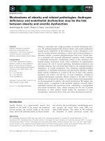
Figure 1—Sample Procedure Specification Form
Note: Dimensions are for example only.
Approximately
1
/16" (1.6 mm)
1
/16" (1.6 mm)
1
/32" –
1
/16" (0.8 – 1.6 mm)
1
/16" ±
1
/32" (1.6 mm ± 0.8 mm)
Standard V-Bevel Butt Joint
T
5
2
1
3
4
Sequence of Beads
Approximately
1
/8"
(3 mm)
T
ELECTRODE SIZE AND NUMBER OF BEADS
Electrode
Size and
Type
Amperage
and
Polarity
Voltage
Bead Number
Speed
Reference: API Standard 1104, 5.2
PROCEDURE SPECIFICATION NO. __________
For _________________________________________ Welding of ________________________________________ Pipe and fittings
Process _____________________________________________________________________________________________________
Material _____________________________________________________________________________________________________
Pipe outside diameter and wall thickness ___________________________________________________________________________
Joint design __________________________________________________________________________________________________
Filler metal and no. of beads _____________________________________________________________________________________
Electrical or flame characteristics __________________________________________________________________________________
Position _____________________________________________________________________________________________________
Direction of welding ____________________________________________________________________________________________
No. of welders ________________________________________________________________________________________________
Time lapse between passes _____________________________________________________________________________________
Type and removal of lineup clamp _________________________________________________________________________________
Cleaning and/or grinding ________________________________________________________________________________________
Preheat/stress relief ____________________________________________________________________________________________
Shielding gas and flow rate ______________________________________________________________________________________
Shielding flux _________________________________________________________________________________________________
Speed of travel ________________________________________________________________________________________________
Plasma gas composition _______________________ Plasma gas flow rate _______________________________________________
Plasma gas orifice size _________________________________________________________________________________________
Sketches and tabulations attached ________________________________________________________________________________
Tested ________________________________________ Welder ________________________________________________
Approved ______________________________________ Welding supervisor ______________________________________
Adopted _______________________________________ Chief engineer __________________________________________
W
ELDING
OF
P
IPELINES
AND
R
ELATED
F
ACILITIES
5
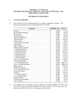
Figure 2—Sample Coupon Test Report
COUPON TEST REPORT
Date __________________________________________________ Test No. __________________________________________
Location _____________________________________________________________________________________________________
State__________________________________________________ Weld Position: Roll ❑ Fixed ❑
Welder ________________________________________________ Mark ____________________________________________
Welding time____________________________________________ Time of day _______________________________________
Mean temperature _______________________________________ Wind break used___________________________________
Weather conditions _____________________________________________________________________________________________
Voltage ________________________________________________ Amperage ________________________________________
Welding machine type_____________________________________ Welding machine size _______________________________
Filler metal ___________________________________________________________________________________________________
Reinforcement size_____________________________________________________________________________________________
Pipe type and grade ____________________________________________________________________________________________
Wall thickness __________________________________________ Outside diameter___________________________________
1 765432
Coupon stenciled
Original specimen dimensions
Original specimen area
Maximum load
❑ Procedure ❑ Qualifying test ❑ Qualified
❑ Welder ❑ Line test ❑ Disqualified
Maximum tensile ______________ Minimum tensile ______________ Average tensile ______________
Remarks on tensile-strength tests ________________________________________________________________________________
1. __________________________________________________________________________________________________________
2. __________________________________________________________________________________________________________
3. __________________________________________________________________________________________________________
4. __________________________________________________________________________________________________________
Remarks on bend tests _________________________________________________________________________________________
1. __________________________________________________________________________________________________________
2. __________________________________________________________________________________________________________
3. __________________________________________________________________________________________________________
4. __________________________________________________________________________________________________________
Remarks on nick-break tests _____________________________________________________________________________________
1. __________________________________________________________________________________________________________
2. __________________________________________________________________________________________________________
3. __________________________________________________________________________________________________________
4. __________________________________________________________________________________________________________
Test made at ___________________________________ Date _________________________________________________
Tested by ______________________________________ Supervised by __________________________________________
Note: Use back for additional remarks. This form can be used to report either a procedure qualification test or a welder qualification test.
Tensile strength
Fracture location
6 API STANDARD 1104
5.3.2.7 Flame Characteristics
The speciÞcation shall designate whether the ßame is neu-
tral, carburizing, or oxidizing. The size of the oriÞce in the
torch tip for each size of rod or wire shall be speciÞed.
5.3.2.8 Position
The speciÞcation shall designate roll or position welding.
5.3.2.9 Direction of Welding
The speciÞcation shall designate whether the welding is to
be performed in an uphill or downhill direction.
5.3.2.10 Time Between Passes
The maximum time between the completion of the root
bead and the start of the second bead, as well as the maxi-
mum time between the completion of the second bead and the
start of other beads, shall be designated.
5.3.2.11 Type and Removal of Lineup Clamp
The speciÞcation shall designate whether the lineup clamp
is to be internal or external or if no clamp is required. If a
clamp is used, the minimum percentage of root-bead welding
that must be completed before the clamp is released shall be
speciÞed.
5.3.2.12 Cleaning and/or Grinding
The speciÞcation shall indicate whether power tools or
hand tools are to be used for cleaning, grinding, or both.
5.3.2.13 Pre- and Post-Heat Treatment
The methods, temperature, temperature-control methods,
and ambient temperature range for pre- and post-heat treat-
ment shall be speciÞed (see 7.11).
5.3.2.14 Shielding Gas and Flow Rate
The composition of the shielding gas and the range of ßow
rates shall be designated.
5.3.2.15 Shielding Flux
The type of shielding ßux shall be designated.
5.3.2.16 Speed of Travel
The range for speed of travel, in inches (millimetres) per
minute, shall be speciÞed for each pass.
5.4 ESSENTIAL VARIABLES
5.4.1 General
A welding procedure must be re-established as a new pro-
cedure speciÞcation and must be completely requaliÞed when
any of the essential variables listed in 5.4.2 are changed.
Changes other than those given in 5.4.2 may be made in the
procedure without the need for re-qualiÞcation, provided the
procedure speciÞcation is revised to show the changes.
5.4.2 Changes Requiring Requalification
5.4.2.1 Welding Process or Method of Application
A change from the welding process or method of applica-
tion established in the procedure speciÞcation (see 5.3.2.1)
constitutes an essential variable.
5.4.2.2 Base Material
A change in base material constitutes an essential variable.
When welding materials of two separate material groups, the
procedure for the higher strength group shall be used. For the
purposes of this standard, all materials shall be grouped
as follows:
a. SpeciÞed minimum yield strength less than or equal to
42,000 psi (290 MPa).
b. SpeciÞed minimum yield strength greater than 42,000 psi
(290 MPa) but less than 65,000 psi (448 MPa).
c. For materials with a speciÞed minimum yield strength
greater than or equal to 65,000 psi (448 MPa), each grade
shall receive a separate qualiÞcation test.
Note: The groupings speciÞed in 5.4.2.2 do not imply that base mate-
rials or Þller metals of different analyses within a group may be indis-
criminately substituted for a material that was used in the qualiÞcation
test without consideration of the compatibility of the base materials
and Þller metals from the standpoint of metallurgical and mechanical
properties and requirements for pre- and post-heat treatment.
5.4.2.3 Joint Design
A major change in joint design (for example, from V
groove to U groove) constitutes an essential variable. Minor
changes in the angle of bevel or the land of the welding
groove are not essential variables.
5.4.2.4 Position
A change in position from roll to Þxed, or vice versa, con-
stitutes an essential variable.
5.4.2.5 Wall Thickness
A change from one wall-thickness group to another consti-
tutes an essential variable.
WELDING OF PIPELINES AND RELATED FACILITIES 7
5.4.2.6 Filler Metal
The following changes in Þller metal constitute essential
variables:
a. A change from one Þller-metal group to another (see
Table 1).
b. For pipe materials with a speciÞed minimum yield
strength greater than or equal to 65,000 psi (448 MPa), a
change in the AWS classiÞcation of the Þller metal
(see 5.4.2.2).
Changes in Þller metal within Þller metal groups may be
made within the material groups speciÞed in 5.4.2.2. The
compatibility of the base material and the Þller metal should
be considered from the standpoint of mechanical properties.
5.4.2.7 Electrical Characteristics
A change from DC electrode positive to DC electrode neg-
ative or vice versa or a change in current from DC to AC or
vice versa constitutes an essential variable.
5.4.2.8 Time Between Passes
An increase in the maximum time between completion of
the root bead and the start of the second bead constitutes an
essential variable.
5.4.2.9 Direction of Welding
A change in the direction of welding from vertical down-
hill to vertical uphill, or vice versa, constitutes an essential
variable.
5.4.2.10 Shielding Gas and Flow Rate
A change from one shielding gas to another or from one
mixture of gases to another constitutes an essential variable.
A major increase or decrease in the range of ßow rates for the
shielding gas also constitutes an essential variable.
5.4.2.11 Shielding Flux
Refer to Table 1, Footnote a, for changes in shielding ßux
that constitute essential variables.
5.4.2.12 Speed of Travel
A change in the range for speed of travel constitutes an
essential variable.
5.4.2.13 Preheat
A decrease in the speciÞed minimum preheat temperature
constitutes an essential variable.
5.4.2.14 Post-Weld Heat Treatment (PWHT)
The addition of PWHT or a change from the ranges or val-
ues speciÞed in the procedure shall each constitute an essen-
tial variable.
5.5 WELDING OF TEST JOINTS—BUTT WELDS
To weld the test joint for butt welds, two pipe nipples
shall be joined, following all the details of the procedure
speciÞcation.
Table 1—Filler Metal Groups
Group
AWS
SpeciÞcation Electrode Flux
c
1 A5.1 E6010, E6011
A5.5 E7010, E7011
2 A5.5 E8010, E8011
E9010
3 A5.1 or A5.5 E7015, E7016, E7018
A5.5 E8015, E8016, E8018
E9018
4
a
A5.17 EL8 P6XZ
EL8K F6X0
EL12 F6X2
EM5K F7XZ
EM12K F7X0
EM13K F7X2
EM15K
5
b
A5.18 ER70S-2
A5.18 ER70S-6
A5.28 ER80S-D2
A5.28 ER90S-G
6 A5.2 RG60, RG65
7 A5.20 E61T-GS
d
E71T-GS
d
8 A5.29 E71T8-K6
9 A5.29 E91T8-G
Note: Other electrodes, Þller metals, and ßuxes may be used but
require separate procedure qualiÞcation.
a
Any combination of ßux and electrode in Group 4 may be used to
qualify a procedure. The combination shall be identiÞed by its com-
plete AWS classiÞcation number, such as F7A0-EL12 or F6A2-
EM12K. Only substitutions that result in the same AWS classiÞca-
tion number are permitted without requaliÞcation.
b
A shielding gas (see 5.4.2.10) shall be used with the electrodes in
Group 5.
c
In the ßux designation, the X can be either an A or P for As Welded
or Post-Weld Heat-Treated.
d
For root-pass welding only.
8 API STANDARD 1104
5.6 TESTING OF WELDED JOINTS—BUTT WELDS
5.6.1 Preparation
To test the butt-welded joint, test specimens shall be cut
from the joint at the locations shown in Figure 3. (See Section
13 for testing requirements for the ßash welding procedure.)
The minimum number of test specimens and the tests to which
they shall be subjected are given in Table 2. The specimens
shall be prepared as shown in Figure 4, 5, 6, or 7. For pipe less
than 2.375 in. (60.3 mm) in outside diameter, two test welds
shall be performed to obtain the required number of test speci-
mens. The specimens shall be air cooled to ambient tempera-
ture prior to being tested. For pipe less than or equal to
1.315 in. (33.4 mm) in outside diameter, one full-section spec-
imen may be substituted for the four reduced-section nick-
break and root-bend specimens. The full-section specimen
shall be tested in accordance with 5.6.2.2 and shall meet the
requirements of 5.6.2.3.
5.6.2 Tensile-Strength Test
5.6.2.1 Preparation
The tensile-strength test specimens (see Figure 4) shall be
approximately 9 in. (230 mm) long and approximately 1 in.
(25 mm) wide. They may be machine cut or oxygen cut, and
no other preparation is needed unless the sides are notched or
are not parallel. If necessary, the specimens shall be machined
so that the sides are smooth and parallel.
5.6.2.2 Method
The tensile-strength test specimens shall be broken under
tensile load using equipment capable of measuring the load at
which failure occurs. The tensile strength shall be computed
by dividing the maximum load at failure by the smallest
cross-sectional area of the specimen, as measured before the
load is applied.
5.6.2.3 Requirements
The tensile strength of the weld, including the fusion zone
of each specimen, shall be greater than or equal to the speci-
Þed minimum tensile strength of the pipe material but need
not be greater than or equal to the actual tensile strength of
the material. If the specimen breaks outside the weld and
fusion zone (that is, in the parent pipe material) and meets the
minimum tensile-strength requirements of the speciÞcation,
the weld shall be accepted as meeting the requirements.
If the specimen breaks in the weld or fusion zone and the
observed strength is greater than or equal to the speciÞed
minimum tensile strength of the pipe material and meets the
soundness requirements of 5.6.3.3, the weld shall be accepted
as meeting the requirements.
If the specimen breaks below the speciÞed minimum ten-
sile strength of the pipe material, the weld shall be set aside
and a new test weld shall be made.
5.6.3 Nick-Break Test
5.6.3.1 Preparation
The nick-break test specimens (see Figure 5) shall be
approximately 9 in. (230 mm) long and approximately 1 in.
(25 mm) wide and may be machine cut or oxygen cut. They
shall be notched with a hacksaw on each side at the center of
the weld, and each notch shall be approximately
1
/
8
inch
(3 mm) deep.
Table 2—Type and Number of Test Specimens for Procedure Qualification Test
Outside Diameter of Pipe Number of Specimens
Inches Millimetres
Tensile
Strength
Nick-
Break
Root
Bend
Face
Bend
Side
Bend Total
Wall Thickness ≤ 0.500 inch (12.7 mm)
< 2.375 < 60.3 0
b
22004
a
2.375Ð4.500 60.3Ð114.3 0
b
22004
> 4.500Ð12.750 114.3Ð323.9 222208
> 12.750 > 323.9 4444016
Wall Thickness > 0.500 inch (12.7 mm)
≤ 4.500 ≤ 114.3 0
b
20024
> 4.500Ð12.750 > 114.3Ð323.9 220048
> 12.750 > 323.9 4400816
a
One nick-break and one root-bend specimen shall be taken from each of two test welds, or for pipe less than or equal to 1.315 inches (33.4 mm)
in diameter, one full-section tensile-strength specimen shall be taken.
b
For materials with speciÞed minimum yield strengths greater than 42,000 psi (290 MPa), a minimum of one tensile test shall be required.
WELDING OF PIPELINES AND RELATED FACILITIES 9
Figure 3—Location of Test Butt-Weld Specimens for Procedure Qualification Test
Top of pipe
Root
bend
Nick-break
See Note 2
Root or
side bend
Nick-break
Top of pipe
Nick-break
Root or
side bend
Greater than or equal to 2.375" (60.3 mm)
but less than or equal to 4.500" (114.3 mm);
also, less than or equal to 4.500" (114.3 mm)
when wall thickness is greater than
0.500" (12.7 mm)
Under
2.375"
(60.3 mm)
Top of pipe
Face or
side bend
Root or
side bend
Nick-break
Tensile
Tensile
Nick-break
Top of pipe
Face or side bend
Face or
side bend
Face or side bend
Tensile
Tensile
Root or side bend
Root or
side bend
Nick-break
Nick-break
Root bend or side bend
Nick-break
Tensile
Face or side bend
Greater than 12.750" (323.9 mm)
Face or side bend
Nick-break
Tensile
Root or side bend
Root or side bend
Greater than 4.500" (114.3 mm)
but less than or equal to
12.750" (323.9 mm)
Notes:
1. At the companyÕs option, the locations may be rotated, provided they are equally spaced around the pipe; however, specimens
shall not include the longitudinal weld.
2. One full-section tensile specimen may be used for pipe with an outside diameter less than or equal to 1.315 in. (33.4 mm).
10 API STANDARD 1104
Figure 4—Tensile-Strength Test Specimen
Figure 5—Nick-Break Test Specimen
Approximately
9" (230 mm)
Approximately
1" (25 mm)
Wall thickness
Weld reinforcement
should not be removed
on either side of specimen
Specimen may be machine or oxygen cut;
edges shall be smooth and parallel
3
/4" (19 mm) min.
Notch cut by hacksaw;
specimen may be machine or
oxygen cut; edges shall be
smooth and parallel
Approximately
1
/8"
(3 mm)
Approximately
1
/8"
(3 mm)
Approximately 9" (230 mm)
Weld reinforcement
should not be removed
on either side of specimen
Wall thickness
Approximately
1
/8" (3 mm)
Transverse notch not to
exceed
1
/16" (1.6 mm) in depth
3
/
4
" (19 mm) min.
Optional nick-break test
specimen for automatic and
semiautomatic welding
WELDING OF PIPELINES AND RELATED FACILITIES 11
Nick-break specimens prepared in this manner from welds
made with certain automatic and semiautomatic processes
may fail through the pipe instead of the weld. When previous
testing experience indicates that failures through the pipe can
be expected, the external reinforcement may be notched to a
depth of not more than
1
/
16
in. (1.6 mm), measured from the
original weld surface.
At the companyÕs option, nick-break specimens for qualiÞ-
cation of a procedure using a semiautomatic or automatic
welding process may be macro-etched prior to being nicked.
5.6.3.2 Method
The nick-break specimens shall be broken by pulling in a
tensile machine, by supporting the ends and striking the center,
or by supporting one end and striking the other end with a ham-
mer. The exposed area of the fracture shall be at least
3
/
4
in.
(19 mm) wide.
5.6.3.3 Requirements
The exposed surfaces of each nick-break specimen shall
show complete penetration and fusion. The greatest dimen-
sion of any gas pocket shall not exceed
1
/
16
in. (1.6 mm), and
the combined area of all gas pockets shall not exceed 2% of
the exposed surface area. Slag inclusions shall not be
more than
1
/
32
in. (0.8 mm) in depth and shall not be more
than
1
/
8
in. (3 mm) or one-half the nominal wall thickness in
length, whichever is smaller. There shall be at least
1
/
2
in.
(13 mm) separation between adjacent slag inclusions. The
dimensions should be measured as shown in Figure 8.
Fisheyes, as deÞned in AWS A3.0, are not cause for rejection.
5.6.4 Root- and Face-Bend Test
5.6.4.1 Preparation
The root- and face-bend test specimens (see Figure 6) shall
be approximately 9 in. (230 mm) long and approximately
1 in. (25 mm) wide, and their long edges shall be rounded.
They may be machine cut or oxygen cut. The cover and root-
bead reinforcements shall be removed ßush with the surfaces
of the specimen. These surfaces shall be smooth, and any
scratches that exist shall be light and transverse to the weld.
5.6.4.2 Method
The root- and face-bend specimens shall be bent in a
guided-bend test jig similar to that shown in Figure 9. Each
specimen shall be placed on the die with the weld at mid
span. Face-bend specimens shall be placed with the face of
the weld toward the gap, and root-bend specimens shall be
placed with the root of the weld toward the gap. The plunger
shall be forced into the gap until the curvature of the speci-
men is approximately U-shaped.
5.6.4.3 Requirements
The bend test shall be considered acceptable if no crack or
other imperfection exceeding
1
/
8
in. (3 mm) or one-half the
nominal wall thickness, whichever is smaller, in any direction is
present in the weld or between the weld and the fusion zone after
bending. Cracks that originate on the outer radius of the bend
along the edges of the specimen during testing and that are less
than
1
/
4
in. (6 mm), measured in any direction, shall not be con-
sidered unless obvious imperfections are observed. Each speci-
men subjected to the bend test shall meet these requirements.
Figure 6—Root- and Face-Bend Test Specimen: Wall Thicknesses Less Than or Equal to 0.500 in. (12.7 mm)
Wall thickness
Approximately 9" (230 mm)
Specimen may be
machine or oxygen cut
1
/8" (3 mm) max;
radius all corners
Approximately 1" (25 mm)
Weld
Note: The weld reinforcement shall be removed from both faces with the surface of the specimen.
The specimen shall not be ßattened prior to testing.
12 API STANDARD 1104
Figure 7—Side-Bend Test Specimen: Wall Thicknesses Greater than 0.500 in. (13 mm)
Figure 8—Dimensioning of Imperfections in Exposed Weld Surfaces
Approximately 9" (230 mm)
1
⁄8" (3-mm) maximum
radius on all corners
Wall thickness
Width of
specimen
Wall thickness
t
t
1
⁄2" (13 mm)
See Note 2
See Note 1
Notes:
1. The weld reinforcement shall be removed from both faces ßush with the surface of the specimen.
2. Specimens may be machine cut to a width of
1
/
2
in. (13 mm), or they may be oxygen cut to a width of approxi-
mately
3
/
4
in. (19 mm) and then machined or ground smooth to a width of
1
/
2
in. (13 mm). Cut surfaces shall be
smooth and parallel.
Depth
LengthSeparation
Note: A broken nick-break test specimen is shown; however, this method of dimensioning
applies also to broken tensile and Þllet weld test specimens.
WELDING OF PIPELINES AND RELATED FACILITIES 13
5.6.5 Side-Bend Test
5.6.5.1 Preparation
The side-bend test specimens (see Figure 7) shall be
approximately 9-in. (230-mm) long and approximately
1
/
2
-in.
(13-mm) wide, and their long edges shall be rounded. They
shall be machine cut, or they may be oxygen cut to approxi-
mately a
3
/
4
-in. (19-mm) width and then machined or ground
to the
1
/
2
-in. (13-mm) width. The sides shall be smooth and
parallel. The cover and root-bead reinforcements shall be
removed ßush with the surfaces of the specimen.
5.6.5.2 Method
The side-bend specimens shall be bent in a guided-bend
test jig similar to that shown in Figure 9. Each specimen shall
be placed on the die with the weld at mid span and with the
face of the weld perpendicular to the gap. The plunger shall
be forced into the gap until the curvature of the specimen is
approximately U-shaped.
5.6.5.3 Requirements
Each side-bend specimen shall meet the root- and face-
bend test requirements speciÞed in 5.6.4.3.
5.7 WELDING OF TEST JOINTS—FILLET WELDS
To weld the test joint for a Þllet weld, a Þllet weld shall be
made to one of the conÞgurations shown in Figure 10, follow-
ing all the details of the procedure speciÞcation.
Figure 9—Jig for Guided-Bend Tests
C
B
A
Note: This Þgure is not drawn to scale. Radius of plunger, A = 1
3
/
4
in. (45 mm); radius of die,
B = 2
5
/
16
in. (60 mm); width of die, C = 2 in. (50 mm).
14 API STANDARD 1104
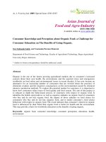
Figure 10 —Location of Nick-Break Test Specimens: Fillet-Weld Procedure and Welder Qualification Test Welds
Figure 11—Location of Nick-Break Test Specimens: Fillet-Weld Procedure and Welder Qualification Test Welds,
Including Size-to-Size, Branch-Connection Welder Qualification Test
Two specimens
from crotch and
two at 90° to
crotch
Note: This Þgure shows the location of test specimens for joints with an outside diameter greater than or equal to 2.375 in. (60.3 mm).
For joints with an outside diameter less than 2.375 in. (60.3 mm), specimens shall be cut from the same general location, but two spec-
imens shall be removed from each of two test welds.
May be hacksaw-notched
1" (25 mm)
approx.
Approx.
45°
Approx.
30°
bevel
Hacksaw cut
Flame cut
1" (25 mm) approx.
2" (50 mm)
approx.
Hacksaw
cut
Flame
cut
2" (50 mm)
approx.
1"
(25 mm)
approx.
WELDING OF PIPELINES AND RELATED FACILITIES 15
5.8 TESTING OF WELDED JOINTS—FILLET WELDS
5.8.1 Preparation
To test the Þllet-welded joint, test specimens shall be cut
from the joint at the locations shown in Figure 10. At least four
specimens shall be taken and prepared as shown in Figure 11.
The specimens may be machine cut or oxygen cut. They should
be at least 1-in. (25-mm) wide and long enough so that they can
be broken in the weld. For pipes less than 2.375 in. (60.3 mm)
in outside diameter, it may be necessary to make two test welds
to obtain the required number of test specimens. The specimens
shall be air cooled to ambient temperature prior to testing.
5.8.2 Method
The Þllet-weld specimens shall be broken in the weld by
any convenient method.
5.8.3 Requirements
The exposed surfaces of each Þllet-weld specimen shall
show complete penetration and fusion, and a) the greatest
dimension of any gas pocket shall not exceed
1
/
16
in.
(1.6 mm), b) the combined area of all gas pockets shall not
exceed 2% of the exposed surface area, c) slag inclusions
shall not be more than
1
/
32
in. (0.8 mm) in depth and shall not
be more than
1
/
8
in. (3 mm) or one-half the nominal wall
thickness in length, whichever is smaller, and d) there shall be
at least
1
/
2
in. (12 mm) separation between adjacent slag
inclusions. The dimensions should be measured as shown in
Figure 8.
6 Qualification of Welders
6.1 GENERAL
The purpose of the welder qualiÞcation test is to determine
the ability of welders to make sound butt or Þllet welds using
previously qualiÞed procedures. Before any production weld-
ing is performed, welders shall be qualiÞed according to the
applicable requirements of 6.2 through 6.8. It is the intent of
this standard that a welder who satisfactorily completes the
procedure qualiÞcation test is a qualiÞed welder, provided the
number of test specimens required by 6.5 have been removed,
tested, and meet the acceptance criteria of 5.6, for each welder.
Prior to starting the qualiÞcation tests, the welder shall be
allowed reasonable time to adjust the welding equipment to
be used. The welder shall use the same welding technique and
proceed with the same speed he will use if he passes the test
and is permitted to do production welding. The qualiÞcation
of welders shall be conducted in the presence of a representa-
tive acceptable to the company.
A welder shall qualify for welding by performing a test on
segments of pipe nipples or on full-size pipe nipples, as spec-
iÞed in 6.2.1. When segments of pipe nipples are used, they
shall be supported so that typical ßat, vertical, and overhead
welds are produced.
The essential variables associated with procedure and
welder qualiÞcations are not identical. The essential variables
for welder qualiÞcation are speciÞed in 6.2.2 and 6.3.2.
6.2 SINGLE QUALIFICATION
6.2.1 General
For single qualiÞcation, a welder shall make a test weld
using a qualiÞed procedure to join pipe nipples or segments
of pipe nipples. The welder shall make a butt weld in either
the rolled or the Þxed position. When the welder is qualifying
in the Þxed position, the axis of the pipe shall be in the hori-
zontal plane, in the vertical plane, or inclined from the hori-
zontal plane at an angle of not more than 45¡.
A welder making a single-qualiÞcation test for branch con-
nections, Þllet welds, or other similar conÞgurations shall fol-
low the speciÞc procedure speciÞcation.
Changes in the essential variables described in 6.2.2
require requaliÞcation of the welder.
The weld shall be acceptable if it meets the requirements of
6.4 and either 6.5 or 6.6.
6.2.2 Scope
A welder who has successfully completed the qualiÞcation
test described in 6.2.1 shall be qualiÞed within the limits of
the essential variables described below. If any of the follow-
ing essential variables are changed, the welder using the new
procedure shall be requaliÞed:
a. A change from one welding processes to another welding
process or combination of processes, as follows:
1. A change from one welding process to a different
welding process; or
2. A change in the combination of welding processes,
unless the welder has qualiÞed on separate qualiÞcation
tests, using each of the welding processes that are to be
used for the combination of welding processes.
b. A change in the direction of welding from vertical uphill
to vertical downhill or vice versa.
c. A change of Þller-metal classiÞcation from Group 1 or 2
to Group 3, or from Group 3 to Group 1 or 2 (see Table 1).
d. A change from one outside-diameter group to another.
These groups are deÞned as follows:
1. Outside diameter less than 2.375 in. (60.3 mm).
2. Outside diameter from 2.375 in. (60.3 mm) through
12.750 in. (323.9 mm).
3. Outside diameter greater than 12.750 in. (323.9 mm).
e. A change from one wall-thickness group to another. These
groups are deÞned as follows: