ULTRA WIDEBAND COMMUNICATIONS: NOVEL TRENDS – ANTENNAS AND PROPAGATION ppt
Bạn đang xem bản rút gọn của tài liệu. Xem và tải ngay bản đầy đủ của tài liệu tại đây (29.42 MB, 396 trang )
ULTRA WIDEBAND
COMMUNICATIONS:
NOVEL TRENDS –
ANTENNAS AND
PROPAGATION
Edited by Mohammad A. Matin
Ultra Wideband Communications: Novel Trends – Antennas and Propagation
Edited by Mohammad A. Matin
Published by InTech
Janeza Trdine 9, 51000 Rijeka, Croatia
Copyright © 2011 InTech
All chapters are Open Access articles distributed under the Creative Commons
Non Commercial Share Alike Attribution 3.0 license, which permits to copy,
distribute, transmit, and adapt the work in any medium, so long as the original
work is properly cited. After this work has been published by InTech, authors
have the right to republish it, in whole or part, in any publication of which they
are the author, and to make other personal use of the work. Any republication,
referencing or personal use of the work must explicitly identify the original source.
Statements and opinions expressed in the chapters are these of the individual contributors
and not necessarily those of the editors or publisher. No responsibility is accepted
for the accuracy of information contained in the published articles. The publisher
assumes no responsibility for any damage or injury to persons or property arising out
of the use of any materials, instructions, methods or ideas contained in the book.
Publishing Process Manager Viktorija Zgela
Technical Editor Teodora Smiljanic
Cover Designer Jan Hyrat
Image Copyright Sarun T, 2010. Used under license from Shutterstock.com
First published July, 2011
Printed in Croatia
A free online edition of this book is available at www.intechopen.com
Additional hard copies can be obtained from
Ultra Wideband Communications: Novel Trends – Antennas and Propagation,
Edited by Mohammad A. Matin
p. cm.
ISBN 978-953-307-452-8
free online editions of InTech
Books and Journals can be found at
www.intechopen.com
Contents
Preface IX
Part 1 UWB Waveform Generation 1
Chapter 1 Ultra-Wideband Waveform
Generation Using Nonlinear
Propagation in Optical Fibers 3
Avi Zadok, Daniel Grodensky, Daniel Kravitz,
Yair Peled, Moshe Tur,
Xiaoxia Wu and Alan E. Willner
Part 2 UWB Channel – Theory and Measurements 25
Chapter 2 Ultra-Wideband (UWB)
Communications Channel
– Theory and Measurements 27
Javad Ahmadi-Shokouh and Robert Caiming Qiu
Chapter 3 Propagation Models for the Characterization
of the Indoor UWB Channel 53
Francisco Saez de Adana
Chapter 4 Frequency UWB Channel 67
Gonzalo Llano, Juan C. Cuellar
and Andres Navarro
Chapter 5 Effects of Bandwidth on Estimation
of UWB Channel Parameters 97
Duje Čoko, Zoran Blažević and Ivan Marinović
Part 3 UWB Pulse Reflection 117
Chapter 6 Ultra Wideband (UWB)
Pulse Reflection from
a Dispersive Medium Half Space 119
Qingsheng Zeng and Gilles Y. Delisle
VI Contents
Part 4 UWB Antennas and Arrays 141
Chapter 7 Planar Monopole UWB Antennas
with Cuts at the Edges and Parasitic Loops 143
Karlo Costa and Victor Dmitriev
Chapter 8 Characteristics of an Ultra-Wideband (UWB)
Butterfly-Shaped Monopole Antenna 155
Qiubo Ye, Zhi Ning Chen and Terence S. P. See
Chapter 9 Performance Study on Modern Ultra
Wideband Monopole Antennas 175
Abdelhalim Mohamed and Lotfollah Shafai
Chapter 10 Ultra-Wideband Printed Antennas Design 195
Mohamed Nabil Srifi
Chapter 11 Printed Sleeve Monopole Antenna 215
Salman Naeem Khan and Muhammad Ashfaq Ahmed
Chapter 12 Design and Implementation
of UWB CPW-Fed Planar Monopole
Antenna with Dual Band Rejection Characteristics 231
Woo Chan Kim and Woon Geun Yang
Chapter 13 Design of a CPW-Fed Dual Band-Notched Planar
Wideband Antenna for UWB Applications 239
Fei Yu and Chunhua Wang
Chapter 14 Coplanar-Microstrip Transitions
for Ultra-Wideband Communications 255
Mohammed El-Gibari, Dominique Averty, Cyril Lupi,
Yann Mahé Hongwu Li and Serge Toutain
Chapter 15 Ultra Wideband Antennas
for High Pulsed Power Applications 277
Baptiste Cadilhon, Bruno Cassany, Patrick Modin,
Jean-Christophe Diot, Valérie Bertrand and Laurent Pécastaing
Chapter 16 UWB Multifunction Antennas 307
Paolo Baldonero, Roberto Flamini,
Antonio Manna and Fabrizio Trotta
Chapter 17 Reconfigurable Antennas
of Wide Tuning Ranges and
Controllable Selectivity Using Matching Networks 335
Chin-Lung Yang and Chieh-Sen Li
Contents VII
Chapter 18 A Novel Directive, Dispersion-Free UWB Radiator with
Superb EM-Characteristics for Multiband/Multifunction
Radar Applications 351
D. Tran, N. Haider, P. Aubry, A. Szilagyi,
I.E. Lager, A. Yarovoy and L.P. Ligthart
Preface
Ultra wideband (UWB) has advanced and merged as a technology, and many more
people are aware of the potential for this exciting technology. The current UWB field is
extremely dynamic, with new techniques and ideas where several issues are involved
in developing the systems, such as antenna design, channel model, and interference.
However, the antenna design for UWB signal is one of the main challenges, especially
when low cost, geometrically small and radio efficient structures are required for
typical applications. It is expected that an appropriate antenna configuration should be
part of a UWB chipset with a full reference design. It requires a theoretical basis for
computation and estimation of antenna design parameters and performance
prediction that determine the performance of precision range and direction
measurements.
This book offers basic as well as advanced research materials for antennas and
propagation. It has taken a theoretical and experimental approach to some extent,
which is more useful to the reader in the long run. The book highlights the unique
design issues which put the reader in a good pace to be able to understand more
advanced research and make a contribution in this field themselves. It is believed that
this book serves as a comprehensive reference for graduate students in UWB antenna
technologies.
Chapter 1 explains the generation of UWB impulse radio using self-phase modulation
in optical fibers. Two different nonlinear mechanisms had been employed: self-phase
modulation (SPM) and Stimulated Brillouin scattering (SBS) for the generation of UWB
waveforms.
Chapter 2 presents a comprehensive overview of UWB measurements of all empirical
data available on various fading properties of indoor radio wave communication
channels. The analytic summaries lead to insights on UWB fading channel
characterization and modeling.
The propagation of the UWB signals in indoor environments is an important task for
the implementation of WPANs which is explained in chapter 3.
Chapter 4 provides a detailed description of the UWB channel in the frequency
domain, using the models defined by IEEE 802.2.15.3a and 802.2.15.4a for High Data
X Preface
Rate Wireless Personal Area Network (HDR-WPAN), Body Area Networks (BAN) and
Sensors Networks, among other applications. A theoretical model for the fade depth
and fading margin of the channel energy is presented in accordance to the parameters
of the IEEE 802.15.4a UWB channel model.
Chapter 5 is about the estimations of the channel parameters which have certain
dependency on the system bandwidth.
Accurate modeling and improved physical understanding of pulse reflection from
dispersive media is crucial in a number of applications, including optical waveguides,
UWB radar, ground penetrating radar, UWB biological effects, stealth technology and
remote sensing which is explained in chapter 6. The time domain technique based on
the numerical inversion of Laplace transform is also developed and extended to the
modeling of ultra wideband pulse reflection from Lorentz, Debye and Cole−Cole
media.
Chapter 7 explores planar antennas which are widely used in UWB systems because of
their low cost of fabrication, low size, and simple structure. In this chapter, four planar
UWB antennas with cuts at the edges and parasitic loops have been analyzed. The
investigated antennas are: a rectangular monopole with two loops, a rectangular
monopole with four loops, a rectangular monopole with cuts at the edges, and a
rectangular monopole with cuts at the edges and two parasitic loops. Here, to enlarge
the matching bandwidth, the dimensions of the antennas were optimized with cut-and
try method.
Chapter 8 presents butterfly-shaped monopole antenna that has demonstrated good
impedance and radiation performance across the UWB band.
Monopole disc antennas, with circular, elliptical and trapezoidal shapes, have simpler
two-dimensional geometries and are easier to fabricate compared to the traditional
UWB monopole antennas with three-dimensional geometries such as spheroidal,
conical and teardrop antennas. In chapter 9, different square, circular and elliptical
disc monopole antenna geometries are designed and analyzed for both
omnidirectional and directional applications. The feeding structure is optimized to
have a maximum impedance bandwidth starting at 3 GHz.
Printed disc monopole antennas are designed in chapter 10 which could be treated as a
good candidate for current and future ultra wideband applications, due to their
attractive features (i.e. small size, low profile, low cost, impedance bandwidth, gain,
nearly omnidirectional radiation).
In chapter 11, rectangular and diamond shaped sleeve UWB antennas are presented
for UWB performance. The analysis of sleeve UWB antenna is also be explained on the
basis of transmission line model of antenna and characteristic modes to get insight
details of the sleeves behavior and their effect on the impedance bandwidth.
Preface XI
In chapter 12, an ultra-wideband coplanar waveguide (CPW)-fed planar monopole
antenna with dual band rejection characteristics is presented. The main problem of the
frequency band rejection design is the difficulty of controlling the bandwidth of the
notch band in a limited space. Furthermore, strong couplings between two adjacent
notch bands design are obstacles to achieve efficient dual band-notched UWB
antennas. Therefore, an efficient frequency bands rejection of the WLAN band and
WiMAX band is difficult to implement for UWB applications.
In chapter 13, a CPW-fed novel planar ultra-wideband antenna with dual band-
notched characteristics is introduced.
Chapter 14 present an ultra-wide bandwidth back-to-back coplanar-microstrip
grounded coplanar waveguide (GCPW-MS-GCPW) transition without making via-
hole in the substrate or patterning the bottom ground plane which simplifies the
manufacturing and facilitates the on-wafer characterization with Ground-Signal-
Ground (GSG) probe station.
The choice and the design of the radiating components of a high power microwave
source are vital as they determine the choice of all or part of the complete system. It
has been explained in chapter 15 that 3D simulations coupled with experimental tests
on prototypes made it possible to refine the various geometrical parameters of the
components to obtain the best possible levels of electromagnetic performance in small
volumes.
Chapter 16 provides an introduction about UWB multifunctional antennas, pointing
out all the main features, advantages and drawbacks, in a quick and easy-to-
understand way before going into the details. The chapter starts with presenting a
brief history of UWB radiating elements, and continues explaining the theory behind
the frequency independent antennas and the feeding techniques, and finally, suggests
a complete design of UWB multifunctional phased array.
In chapter 17, a novel design method is presented for reconfigurable antennas that are
independent of the geometries and the dimensions of the antennas, providing wide
tuning ranges and controllable selectivity.
The design methodology and conceptual approach of the super wideband (SWB)-
prototype has been discussed in chapter 18.
I hope that students will find this book useful as a learning tool for research in this
exciting field.
Mohammad A. Matin
North South University
Bangladesh
Part 1
UWB Waveform Generation
1
Ultra-Wideband Waveform Generation Using
Nonlinear Propagation in Optical Fibers
Avi Zadok
1
, Daniel Grodensky
1
, Daniel Kravitz
1
, Yair Peled
2
,
Moshe Tur
2
, Xiaoxia Wu
3
and Alan E. Willner
3
1
Bar-Ilan University
2
Tel-Aviv University
3
University of Southern California
1,2
Israel
3
USA
1. Introduction
Ultra-wideband (UWB) radio is a transmission technology that is based on short pulses,
whose spectral width is on the order of several GHz. UWB signals are free of sine-wave
carriers, and their duty cycle and power spectral density are low. These characteristics
provide UWB radio with unique advantages: improved immunity to multi-path fading,
increased ranging resolution, large tolerance to interfering legacy systems, enhanced ability
for penetrating obstacles, and low electronic processing complexity at the receiver. UWB
technology is considered attractive for a myriad of applications, including high-speed
internet access, sensor networks, high accuracy localization, precision navigation, covert
communication links, ground-penetrating radar, and through-the-wall imaging (Yang &
Giannakis, 2004).
Of the various potential UWB radio applications, much attention has turned to wireless
personal area networks, which address short-range, ad-hoc, and high-rate connectivity
among portable electronic devices. UWB radio is among the standards that are being
considered to replace cables in such networks, due to its multi-path and interference
tolerance, low power, and high efficiency. Research efforts in this area have intensified since
2002 when the United States Federal Communication Commission (FCC) allocated the
frequency range of 3.6-10.1 GHz for unlicensed, UWB indoor wireless communication
(Federal Communications Commission [FCC], 2002). Interest is not limited to indoor
wireless communication only: the FCC report relates to imaging systems and vehicular
radar systems as well (FCC, 2002). The vehicular radar standard, in particular, specifies a
high central frequency of 24 GHz or higher (FCC, 2002). The electronic generation of
complex UWB waveforms at such high frequencies is increasingly challenging.
The FCC standard imposes several limitations on the transmitted signals. First, the power
spectral density must comply with complicated spectral masks (FCC, 2002). In addition, the
total signal power is severely restricted, limiting the range of UWB indoor wireless
transmission, for example, to only 10-15 m. In many scenarios, UWB radio-based systems
would need to extend their wireless transmission range by other distribution means. As the
Ultra Wideband Communications: Novel Trends – Antennas and Propagation
4
frequencies of UWB signals continue to increase, with 100 GHz transmission already
reported (Chow et al., 2010), optical fibers become the preferable distribution medium. With
radio-over-fiber integration on the horizon, the generation of the UWB pulses by photonic
methods becomes attractive. Microwave-photonic generation techniques can offer flexible
tuning of high-frequency pulse shapes, inherent immunity to electromagnetic interference,
and parallel processing via wavelength division multiplexing (Capmany et al., 2005). Driven
by the promises of integration and flexibility, much research effort has been dedicated to
photonic generation of UWB waveforms in recent years.
Most microwave-photonic UWB generation schemes thus far target impulse radio
implementations: the transmission of tailored short pulses and their subsequent coherent
detection. One category of photonic UWB generation techniques relied on the conversion of
phase to intensity modulation (Yao et al., 2007; Zeng & Yao, 2006; Zeng et al., 2007). This
method is simple to implement, however it offers few degrees of freedom for pulse shaping
and minimal reconfiguration. Waveforms generated using this method are restricted to a
Gaussian mono-cycle or a Gaussian doublet shape. Higher-order pulse shapes were
generated based on microwave-photonic tapped delay line filters, with both positive and
negative coefficients (Bolea et al., 2009; Bolea et al., 2010). Pulse generation based on four-
coefficient filters had been demonstrated (Bolea et al., 2009), however each additional
coefficient required an extra laser source.
Another interesting approach is based on nonlinear dynamics in semiconductor optical
amplifiers (SOAs) and laser diodes. Cross-gain modulation (XGM) effects in SOAs and
cross-absorption effects in electro-absorption modulators had been used in Gaussian
monocycle and doublet waveform generation (Ben-Ezra et al., 2009; Wu, et al., 2010; Xu et
al., 2007a, 2007b). Relaxation oscillations in directly-modulated or externally-injected
distributed feedback lasers were recently demonstrated as well (Gibbon et al., 2010; Pham et
al., 2011; Yu et al., 2009). The technique is well suited to the FCC spectral mask for indoor
wireless communication: wireless transmission of 3.125 Gbits/s, employing high-order
waveforms, had been experimentally demonstrated (Gibbon et al., 2010; Pham et al., 2011).
On the other hand, waveform generation based on relaxation oscillations is restricted to the
order of 10 GHz by the laser diode dynamics.
The most elaborate waveform tailoring was provided by optical spectrum shaping and
subsequent frequency-to-time mapping (Abtahi et al., 2008a, 2008b, 2008c; McKinney et al.,
2006; McKinney, 2010). These techniques relied on careful spectral shaping of the
transmitted waveforms in order to maximize the transmitted power within the constraints
of the FCC mask. However, the demonstrations required mode-locked laser sources, and
either bulky free-space optics (McKinney et al., 2006; McKinney, 2010) or highly complex
fiber gratings with limited tuning (Abtahi et al., 2008a, 2008b, 2008c). Major progress had
been recently achieved, with the pulse-shaping optics successfully replaced by a
programmable, integrated silicon-photonic waveguide circuit (Khan et al., 2010).
Nonlinear propagation effects in optical fibers are powerful tools for optical signal
processing. However, they have been seldom used in UWB pulse generation research. Li
and coauthors used cross-gain modulation in an optical parametric amplifier to generate
monocycle and doublet pulse shapes (Li et al., 2009). Velanas and coauthors used a cross-
phase-modulation (XPM) based technique to obtain monocycle shapes (Valenas et al., 2008).
Both schemes required two input laser sources.
In the first section of this work, we use nonlinear propagation of a pulse train from a single
laser source for the generation of high-order UWB impulse radio waveforms (Zadok et al.,
Ultra-Wideband Waveform Generation Using Nonlinear Propagation in Optical Fibers
5
2009; Zadok et al., 2010a, 2010b, ©2010 IEEE). All-optical edge detectors of the input pulses
intensity are used to generate two temporally-narrowed replicas of the input pulse train.
The edge detection relies on the time-varying chirp introduced by self-phase modulation
(SPM), and judiciously tuned optical filters. SPM accumulates through propagation along
sections of fiber, which can also serve for the distribution of pulses from a network terminal
to a remote antenna element. The shapes of the narrowed replicas are subtracted from that
of the original pulse train in a broadband, balanced differential detector. The resulting
waveforms are highly reconfigurable through adjustments of the input power and tuning of
the optical filters. High-order UWB waveforms, having a center frequency of 34 GHz and a
fractional bandwidth of 70% are generated.
UWB architectures that are based on impulse radio require elaborate pulse shaping and a
detailed knowledge of the communication channel properties (Qiu et al., 2005; Yang &
Giannakis 2004). A possible alternative is the transmission of modulated, broadband noise
waveforms. One such implementation relies on direct energy detection (Sahin et al., 2005).
Incoherent detection, however, compromises the immunity to interference of UWB
technology. Coherent detection can be restored using transmit-reference (TR) schemes, in
which the modulated noise is accompanied by a delayed, unmodulated replica of itself
(Narayanan & Chuang, 2007). Data is recovered by a matched delay at the receiver end
(Narayanan & Chuang, 2007), and knowledge of the channel response is not required (Sahin
et al., 2005). Photonic generation of UWB noise has been demonstrated recently, based on
the chaotic dynamics of a laser diode in a feedback loop (Zheng et al., 2010).
In the second part of this work we propose, analyze and demonstrate the photonic
generation of UWB noise, based on the amplified spontaneous emission associated with
stimulated Brillouin scattering in optical fibers (SBS-ASE) (Peled et al., 2010, ©2010 IEEE).
The noise bandwidth is extended to 1.1 GHz, using a recently proposed method for
broadening of the SBS process (Zadok et al., 2007). Gaussian noise of such bandwidth can be
readily generated electrically, however photonic generation techniques are appealing from a
radio-over-fiber integration standpoint (Yao et al., 2007). Both direct detection and TR-
assisted coherent detection are demonstrated. The performance is in agreement with the
theoretical analysis.
Finally, as noted above, UWB waveforms find applications in various radar systems. Noise-
based waveforms, in particular, provide better immunity to interception and jamming
(Chuang et al., 2008; Narayanan, 2008). Similarly to UWB communication, photonic
techniques could provide flexible and reconfigurable generation of broadband, high-carrier
frequency noise waveforms, integrated with simple long-reach distribution. In the last
section of this work, we show preliminary ranging measurements of metal objects based on
SBS-ASE noise waveforms.
2. UWB impulse radio generation using self-phase modulation in optical
fibers
2.1 Self-phase modulation based edge detection
Consider the optical field
(
)
in
Et
of an input train of super-Gaussian pulses (Zadok et al.,
2010b, ©2010 IEEE):
()
()
0
0
0
exp exp
2
m
in in
n
tnT
Et P jt
⎡⎤
⎡⎤−
=
−ω
⎢⎥
⎢⎥
τ
⎣⎦
⎢⎥
⎣
⎦
∑
, (1)
Ultra Wideband Communications: Novel Trends – Antennas and Propagation
6
with a peak power level
in
P , central optical frequency
0
ω
, width parameter
0
τ and pulse
separation
0
T . The parameter m determines the exact shape of the input pulses, and t
denotes time. In propagating along a highly nonlinear fiber (HNLF) of length L [km] and
negligible dispersion, the optical field undergoes SPM:
() () () () ()
2
exp exp
HNLF in in in
EtEt
j
tEt
j
LE t
⎡
⎤
=⎡ϕ⎤= γ
⎣⎦
⎣
⎦
(2)
where γ [W · km]
-1
is the nonlinear coefficient of the fiber. The nonlinearly induced phase
modulation
()
tϕ represents an effective temporally-varying shift of the optical frequency
(chirp):
()
()
()
2
d
d
1
2d 2 d
in
pulse
Et
t
L
ft
tt
ϕ
γ
Δ= =
ππ
(3)
Figure 1 shows the instantaneous power
()
2
in
Et of a single input super-Gaussian pulse
with
m = 5 (top panel), and the corresponding
(
)
pulse
f
tΔ for a 1 km-long HNLF with γ = 11.3
[W · km]
-1
(bottom panel). The leading (trailing) edge of the pulse is associated with a
positive (negative) frequency shift. Edge detection of
(
)
HNLF
Etis implemented by an optical
bandpass filter (BPF) of spectral width 2
δ, detuned from
0
ω
by a frequency offset
0
Δω > δ > . The BPF would block most of the waveform, except for a segment of sufficient
SPM:
(
)
2
pulse
ftπ⋅Δ >Δω−δ. As seen in equation (3), this segment corresponds to the leading
edge of the pulse. The BPF therefore represents an all-optical intensity edge detector. The
details of the narrowed replica of the pulse at the BPF output are determined by its spectral
width and detuning as well as the input power
in
P . The endpoints of the filtered waveform
1,2
t are approximately given by:
()
()
2
1,2
dd
in
Et t L
=
Δω −δ γ . The trailing edge can be
filtered in a similar manner, with 0
Δ
ω< , 0
Δ
ω>δ> . Figure 2 shows the instantaneous
power
()
2
Et
±
at the output of two 75 GHz-wide BPFs, whose central frequencies are
detuned from
0
ω by 2
±
Δ
ωπ= ± 135 GHz, respectively. As expected, the filtered waveforms
emphasize the pulse edges, and both are narrower than the original input pulse. The shape
of the two narrowed replicas can be subtracted from that of the original pulse to generate an
UWB waveform, as described next.
2.2 UWB waveform generation using all-optical edge detectors
Figure 3 shows a schematic drawing of a setup for UWB waveform generation, based on all-
optical edge detection (Zadok et al., 2010b, ©2010 IEEE). The input super-Gaussian pulse
train is split in two branches. The upper branch includes a high-power erbium-doped fiber
amplifier (EDFA) and an HNLF section. At the HNLF output, the spectrally broadened
pulses are split into two paths once again, and the light in each path is filtered by an
individually tunable BPF: one is tuned to detect the pulse leading edge as discussed above,
whereas the other is adjusted as a trailing edge detector. The power level of each of the two
pulse train replicas is individually adjusted by a variable optical attenuator (VOA). In
addition, the relative delay between the two pulse trains can be modified by a tunable delay
line (TDL). The two pulse trains are then joined together and directed to the negative port of
a balanced, differential detector. Since the difference between the central frequencies of the
two replicas is outside the detector bandwidth, beating between the two is largely avoided.
Ultra-Wideband Waveform Generation Using Nonlinear Propagation in Optical Fibers
7
A reference pulse train, arriving from the lower branch of the setup, is detected at the
positive port of the balanced detector. The relative delay and magnitude of the reference
pulse train are controlled by a second EDFA and TDL.
Fig. 1. Top - instantaneous power of an input super-Gaussian pulse: m = 5,
0
τ
= 27 ps,
in
P =
1.7 W. Bottom – simulated SPM-induced instantaneous frequency shift
(
)
pulse
f
tΔ : L = 1 km, γ
= 11.3 [W·km]
-1
. Horizontal shaded regions in the bottom panel schematically denote the
passbands of two detuned optical filters. Vertical dashed lines schematically illustrate the
temporal edges of the corresponding waveforms at the filters output. ©2010 IEEE.
-100 -50 0 50 100
0
0.5
1
1.5
2
Time [ps]
Power [W]
Fig. 2. Solid - instantaneous power of an input super-Gaussian pulse (same as top panel of
Fig. 1). Dashed – simulated instantaneous pulse power following propagation in a HNLF
and filtering by a 75 GHz-wide BPF, detuned from
0
ω
by 2
+
Δ
ωπ= 135 GHz. HNLF
parameters are the as those in the bottom panel of Fig. 1. Dashed-dotted – same as dashed
curve, with the BPF detuned from
0
ω
by 2
−
Δ
ωπ= -135 GHz. ©2010 IEEE.
Ultra Wideband Communications: Novel Trends – Antennas and Propagation
8
Fig. 3. A schematic diagram of the UWB pulse generation scheme. EDFA: erbium-doped
fiber amplifier; HNLF: highly nonlinear fiber; BPF: bandpass filter; VOA: variable optical
attenuator; TDL: tunable delay line. ©2010 IEEE.
The electrical waveform at the balanced detector output can be expressed as:
() () () ()
222
in
Vt Et aEtt aEtt
++ + −− −
∝−−−− (4)
where a
±
and t
±
are the relative power levels and delays of the leading and trailing edge
waveforms, respectively. Unless corrected by the TDLs, the relative delays
t
±
correspond to
max (min) of the input intensity derivative. The complete waveform design requires a
numeric calculation. Nonetheless, the following relations may serve as useful starting
points:
1
2
0
tt
+−
=− ≈ τ ,
() ()
22
1
2
in
a Etdt Etdt
±+
≈
∫∫
. The central frequency
C
f
of
(
)
Vtis on
the order of
21
1 tt
−
, where
21
tt
−
is the temporal width of the narrowed replica at the
output of the edge detectors (see previous section).
Figure 4 shows a simulated example of the normalized shape of
(
)
Vt (top panel) and its
corresponding power spectral density
()
2
V
Ω
(bottom), where Ω represents a radio
frequency (RF) variable. The calculation parameters were the same as those of the previous
section, with
1.85a
±
=
and 10t
±
=
± ps. The central frequency
C
f
of the high-order, UWB
output waveform is 34 GHz. The high and low -10 dB cutoff frequencies
,HL
f
are 47 GHz
and 23 GHz, respectively, providing a fractional bandwidth
(
)
f
rHLC
B
fff
≡− of 70%.
(
)
Vt
can be simply modified through changing the peak power, width and shape of the incoming
pulse train, the detuning of the BPFs, and the relative magnitude and delay of the replica
trains of narrowed pulses. Experimental generation of UWB waveform is described next.
Ultra-Wideband Waveform Generation Using Nonlinear Propagation in Optical Fibers
9
-100 -50 0 50 100
-1
-0.5
0
0.5
1
Time [ps]
Rel. Volt
0 10 20 30 40 50 60
-30
-20
-10
0
Frequency [GHz]
Relative RF spectrum [dB]
Fig. 4. Top – Simulated output waveform
(
)
Vt. The input pulse, HNLF and BPFs
parameters are the same as those of Figs. 1 and 2,
1.85a
±
=
and 10t
±
=
± ps. Bottom – the
corresponding RF spectrum
()
2
V
Ω
. ©2010 IEEE.
2.3 Experimental results
The generation of UWB pulses was demonstrated experimentally, using the setup of Fig. 3
(Zadok et al., 2010b, ©2010 IEEE). The parameters of the input pulse train and HNLF, and
the settings of the BPFs, VOAs and TDLs were the same as those of the previous sections.
The separation
0
T between neighboring pulses was 600 ps, corresponding to a data rate of
1.67 Gb/s. The average power of the amplified, input pulse train was 160 mW. Figure 5
shows the measured optical spectra
()
2
in
E
λ
,
()
2
HNLF
E
λ
and
()
2
E
±
λ
, corresponding to
()
in
Et,
()
HNLF
Et and
(
)
Et
±
respectively, as a function of wavelength λ.
Figure 6 (top) shows the measured
(
)
Vt alongside the corresponding simulation. The
experimental RF spectrum
()
2
V
Ω
, calculated by taking the Fourier transform of the
measured
()
Vt, is shown at the bottom of Fig. 6 alongside the simulated results. The
experimental waveform generally agrees with the simulation.
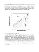
The flexibility of the waveform generation method is illustrated in Fig. 7 (Zadok et al., 2009;
Zadok et al., 2010a), in which the setup parameters were adjusted to approximate the FCC
mask for unlicensed indoor wireless UWB communication (FCC, 2002). In this experiment,
Gaussian pulses (
m = 2) of width
0
τ
= 100 ps, peak power
in
P = 1 W and spacing
0
T = 800
ps were used. Only a single edge detection BPF was used in the experiment, with a spectral
width of 40 GHz and detuning
2
Δ
ωπof 30 GHz. The normalized output waveform
()
Vt
approximates a Gaussian doublet pulse shape (top panel). The calculated
()
2
V Ω
is drawn
Ultra Wideband Communications: Novel Trends – Antennas and Propagation
10
on the lower panel, alongside the FCC mask. The measurement generally complies with the
mask requirements, although infringements can be seen at the lower frequency range.
1552 1553 1554 1555 1556 1557
-50
-45
-40
-35
-30
-25
-20
-15
-10
Wavelength [nm]
Power [dBm]
Fig. 5. Measured optical power spectra corresponding to
(
)
in
Et (dashed, black),
(
)
HNLF
Et
(dotted, blue),
(
)
Et
+
(solid, magenta) and
(
)
Et
−
(dashed-dotted, red). The experimental
parameters were the same as those of the simulations in Fig. 4. ©2010 IEEE.
The FCC mask infringements of the experimental Fig. 7 can be considerably reduced with
the use of a narrower BPF: Figure 8 shows an example of simulated
(
)
Vt and
()
2
V Ω
obtained with a single 10-GHz wide BPF. Results may be further improved by using two
BPFs, as in Fig. 6.
2.4 Discussion and future work
The proposed technique for the photonic generation of UWB relies on all-optical detection of
intensity edges of incoming super-Gaussian pulses. The technique could be particularly
suitable for high-frequency waveforms, such as those intended for high-resolution vehicular
radar systems. The edge detectors were implemented based on SPM in a section of HNLF,
and using two BPFs in parallel. However, both edges might be detected simultaneously
with the application of just one band-stop optical filter centered at
0
ω
, which would remove
the center of the pulse (see Fig. 1). Data can be transmitted through simple on-off keying of
the input pulses. On the other hand, pulse polarity modulation is not simply supported by
the proposed approach.
The waveform generation setup includes multiple optical paths, the lengths of which were
not matched in the experiment. The integrity of the UWB shape in a data-carrying,
operational system could require path length equalization on mm scale. The problem might
Ultra-Wideband Waveform Generation Using Nonlinear Propagation in Optical Fibers
11
be alleviated by using short fiber spans and high peak power levels, environmental isolation
of fiber sections or active compensation. Alternatively, the relative delays
t
±
could be
controlled using dispersion rather than TDLs along different paths. The stability of the
experimental setup was thus far validated over a couple of hours. Long term stability was
not tested. The transmission of actual data using the proposed approach is the subject of
further work.
-100 -50 0 50 100
-1
-0.5
0
0.5
1
Time [ps]
Rel. Volt
0 10 20 30 40 50 60
-30
-20
-10
0
Frequency [GHz]
Relative RF spectrum [dB]
Fig. 6. Top – Simulated (solid, blue) and measured (dashed, red) output waveform
(
)
Vt.
The experimental parameters were the same as those of the simulations in Fig. 4. Bottom –
the corresponding simulated (solid, blue) and calculated experimental (dashed, red) RF
spectra
()
2
V Ω . ©2010 IEEE.
The shaping and distribution scheme of the UWB pulses requires a two-fiber connection
between a transmitter and a remote antenna element. Single-fiber transmission would be
possible if a reference pulse shape
()
2
in
Et could be extracted from the SPM-broadened
(
)
HNLF
Et
at the receiver. Ideally
() ()
22
HNLF in
Et Et= , however residual dispersion and EDFA
noise might distort the reference pulse shape. A potential solution might be narrow-band
optical filtering centered at
0
ω
.
The comparison of the technique proposed in this work to previous approaches draws
interesting analogies. Here, SPM introduces a time-to-frequency mapping, in which
different temporal sections of the input pulses acquire different frequency shifts. This
process is somewhat analogous to frequency-to-time mapping-based techniques (Abtahi et
al., 2008a; McKinney et al., 2006; Wang et al., 2007), in which dispersion is used to assign a
different delay to different spectral components of an input waveform. The subtraction of
Ultra Wideband Communications: Novel Trends – Antennas and Propagation
12
the intensity profile of delayed replicas from the original pulse shape might be viewed as a
tapped-delay line filtering method. It should be noted, though, that the subtracted
waveforms are obtained through nonlinear processing and are not scaled copies of the
input. The nonlinear propagation enables the generation of higher-order waveforms while
using only two replicas, and also allows for simple reconfiguration through input power
adjustments.
0 5 10 15 20
-80
-60
-40
Frequency [GHz]
Power [dBm/MHz]
-400 -200 0 200 400
-1
-0.5
0
0.5
Time [ps]
Norm. power
Fig. 7. Top– measured
(
)
Vt. Bottom– calculated experimental RF power spectrum
()
2
V Ω
(solid), alongside the FCC mask for indoor UWB communication (FCC, 2002) (dashed).
Input parameters:
in
P = 1 W,
0
τ
= 100 ps , m = 2,
0
T = 800 ps. HNLF parameters: L = 1 km, γ
= 11.3 [W
⋅km]
-1
. A single 40-GHz wide BPF was used, detuned by 2
Δ
ωπ = 30 GHz. ©2010
IEEE.
3. UWB noise waveforms generation using stimulated Brillouin scattering
amplified spontaneous emission
As discussed above, impulse radio UWB communication requires elaborate pulse shaping,
using either electrical or optical means. Alternatively, the criteria of UWB transmission may
be met based on modulated noise waveforms, which could be simpler to generate. UWB
noise communication had been previously proposed and demonstrated in several works
(Haartsen et al., 2004; Haartsen et al., 2005; Narayanan & Chuang, 2007; Sahin et al., 2005).
However, only few studies examined the use of optical techniques for noise generation. In
one such recent example (Zheng et al., 2010), UWB noise was generated based on the chaotic
dynamics of a laser diode within a fiber-optic feedback loop. UWB noise can be readily
generated using electrical techniques (Upadhyaya, 1999), however optical methods are
nonetheless appealing as part of a radio-over-fiber integrated system.
Ultra-Wideband Waveform Generation Using Nonlinear Propagation in Optical Fibers
13
0 5 10 15 20
-80
-60
-40
Frequency [GHz]
Power [dBm/MHz]
-400 -200 0 200 400
-1
-0.5
0
0.5
Time [psec]
Norm. power
Fig. 8. Top– simulated
(
)
Vt. Bottom– corresponding simulated RF power spectrum
()
2
V Ω
(solid), alongside the FCC mask for indoor UWB communication (FCC, 2002) (dashed).
Input pulses parameters:
in
P = 1 W,
0
τ
= 70 ps , m = 2. HNLF parameters: L = 1 km, γ = 11.3
[W
⋅km]
-1
. A single 10-GHz wide BPF was detuned from
0
ω
by 2
Δ
ωπ = 20 GHz. ©2010
IEEE.
The rejection of interfering signals in UWB receivers relies on a proper matched filtering of
incoming waveforms. The matched filter, in turn, requires precise knowledge of the
transmitted pulse shapes and the transfer properties of the communication channel. In
noise-based UWB schemes, a reference waveform must be provided to the receiver
separately. In such transmit-reference (TR) techniques, an unmodulated replica of the data-
carrying noise waveform is transmitted in parallel. Data and reference can by time-
multiplexed, or launched at different intermediate frequencies or over two orthogonal
polarizations (Narayanan and Chuang, 2007). TR UWB communication based on optically
generated waveforms is demonstrated below.
3.1 Broadband noise generation
Stimulated Brillouin scattering (SBS) requires the lowest activation power of all non-linear
effects in silica optical fibers. In SBS, a strong pump wave and a typically weak, counter-
propagating signal wave optically interfere to generate, through electrostriction, a traveling
longitudinal acoustic wave. The acoustic wave, in turn, couples these optical waves to each
other (Boyd, 2008). The SBS interaction is efficient only when the difference between the
optical frequencies of the pump and signal waves is very close (within a few tens of MHz) to
a fiber-dependent parameter, the Brillouin shift
B
Ω
, which is of the order of 2π⋅11 GHz in
silica fibers at room temperature and at 1550 nm wavelength (Boyd, 2008). An input signal