Source: MASONRY DESIGN AND DETAILING pdf
Bạn đang xem bản rút gọn của tài liệu. Xem và tải ngay bản đầy đủ của tài liệu tại đây (14.73 MB, 584 trang )
PA R T 1
INTRODUCTION
Downloaded from Digital Engineering Library @ McGraw-Hill (www.digitalengineeringlibrary.com)
Copyright © 2004 The McGraw-Hill Companies. All rights reserved.
Any use is subject to the Terms of Use as given at the website.
Source: MASONRY DESIGN AND DETAILING
Downloaded from Digital Engineering Library @ McGraw-Hill (www.digitalengineeringlibrary.com)
Copyright © 2004 The McGraw-Hill Companies. All rights reserved.
Any use is subject to the Terms of Use as given at the website.
INTRODUCTION
3
1
HISTORY AND
DEVELOPMENT OF
MASONRY TECHNOLOGY
The unwritten record of history is preserved in buildings—in temples,
fortresses, sanctuaries, and cities constructed of brick and stone. Early
efforts to build permanent shelter were limited to the materials at hand. The
trees of a primeval forest, the clay and mud of a river valley, the rocks, caves,
and cliffs of a mountain range afforded only primitive opportunity for protec-
tion, security, and defense and few examples survive. But the stone and brick
of skeletal architectural remains date as far back as the temples of Ur built
in 3000
B.C., the early walls of Jericho of 8000 B.C., and the vaulted tombs at
Mycenae of the fourteenth century B.C. It was the permanence and durability
of the masonry which safeguarded this prehistoric record of achievements,
and preserved through centuries of war and natural disaster the traces of
human development from cave dweller to city builder. Indeed, the history
of civilization is the history of its architecture, and the history of architecture
is the history of masonry.
1.1 DEVELOPMENT Stone is the oldest, most abundant, and perhaps the most important raw
building material of prehistoric and civilized peoples. Stone formed their
defense in walls, towers, and embattlements. They lived in buildings of
stone, worshiped in stone temples, and built roads and bridges of stone.
Builders began to form and shape stone when tools had been invented that
were hard enough to trim and smooth the irregular lumps and broken
surfaces. Stone building was then freed from the limitations of monolithic
slab structures like those at Stonehenge and progressed through the shaped
and fitted blocks of the Egyptians to the intricately carved columns and
entablatures of the Greeks and Romans.
Downloaded from Digital Engineering Library @ McGraw-Hill (www.digitalengineeringlibrary.com)
Copyright © 2004 The McGraw-Hill Companies. All rights reserved.
Any use is subject to the Terms of Use as given at the website.
Source: MASONRY DESIGN AND DETAILING
Brick is the oldest manufactured building material, invented almost
10,000 years ago. Its simplicity, strength, and durability led to extensive use,
and gave it a dominant place in history alongside stone.
Rubble stone and mud bricks, as small, easily handled materials, could
be stacked and shaped to form enclosures of simple or complex design. Hand-
shaped, sun-dried bricks, reinforced with such diverse materials as straw
and dung, were so effective that kiln-fired bricks did not appear until the
third millennium
B.C., long after the art of pottery had demonstrated the
effects of high temperatures on clay. Some of the oldest bricks in the world,
taken from archaeological digs at the site of ancient Jericho, resemble long
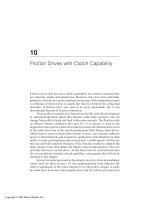
loaves of bread with a bold pattern of Neolithic thumbprint impressions on
their rounded tops (see Fig. 1-1). The use of wooden molds did not replace
such hand-forming techniques until the early Bronze Age, around 3000 B.C.
Perhaps the most important innovations in the evolution of architecture
were the development of masonry arches and domes. Throughout history, the
arch was the primary means of overcoming the span limitations of single blocks
of stone or lengths of timber, making it possible to bridge spaces once thought
too great. Early forms only approximated true “arching” action and were gener-
ally false, corbeled arches. True arches carry their loads in simple compression
to each abutment, and as long as the joints are roughly aligned at right angles
to the compressive stress, the precise curve of the arch is not critical.
The excavation of ruins in Babylonia exposed a masonry arch believed
to have been built around 1400 B.C. Arch construction reached a high level of
refinement under the Romans, and later developments were limited primarily
to the adaptation of different shapes. Islamic and Gothic arches led to the
design of groined vaults, and eventually to the high point of cathedral archi-
tecture and masonry construction in the thirteenth century.
Simple dome forms may actually have preceded the true arch because,
like the corbeled arch, they could be built with successive horizontal rings of
masonry, and required no centering. These domes were seen as circular walls
gradually closing in on themselves rather than as rings of vertical arches.
Barrel vaults were built as early as the thirteenth century
B.C., and could
also be constructed without centering if one end of the vault was closed off.
Initial exploitation of the true dome form took place from the mid–first
century
A.D. to the early second century, under the reigns of Nero and
Hadrian. The brick dome of the Pantheon in Rome exerts tremendous out-
ward thrusts counteracted only by the massive brick walls encircling its
perimeter. Later refinements included the masonry squinch and pendentive,
which were instrumental in the construction of the dome of the Florence
Cathedral, and buttressing by means of half domes at the sides, as in the
Church of Hagia Sophia in Constantinople.
4 Chapter 1 History and Development of Masonry Technology
Figure 1-1 Sun-dried brick, circa 8000 B.C.
Downloaded from Digital Engineering Library @ McGraw-Hill (www.digitalengineeringlibrary.com)
Copyright © 2004 The McGraw-Hill Companies. All rights reserved.
Any use is subject to the Terms of Use as given at the website.
HISTORY AND DEVELOPMENT OF MASONRY TECHNOLOGY
1.2 DECLINE Renaissance architecture produced few significant innovations in structural
building practices, since designs were based primarily on the classical forms of
earlier eras. The forward thrust of structural achievements in masonry
essentially died during this period of “enlightenment,” and masonry structures
remained at an arrested level of development.
With the onslaught of the Industrial Revolution, emphasis shifted to
iron, steel, and concrete construction. The invention of portland cement in
1824, refinements in iron production in the early nineteenth century, and the
development of the Bessemer furnace in 1854 turned the creative focus of
architecture away from masonry.
By the early twentieth century, the demand was for high-rise construc-
tion, and the technology of stone and masonry building had not kept pace
with the developments of other structural systems. The Chicago School had
pioneered the use of iron and steel skeleton frames, and masonry was relegated
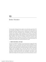
to secondary usage as facings, in-fill, and fireproofing. The Monadnock
Building in Chicago (1891) is generally cited as the last great building in the
“ancient tradition” of masonry architecture (see Fig. 1-2). Its 16-story unrein-
forced loadbearing walls were required by code to be several feet thick at the
base, making it seem unsuited to the demands of a modern industrialized
society. Except for the revivalist periods following the 1893 World’s Columbian
Exposition and the “mercantile classicism” which prevailed for some time, a
general shift in technological innovation took place, and skeleton frame con-
struction began to replace loadbearing masonry.
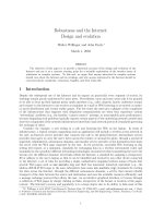
During this period, only Antonio Gaudi’s unique Spanish architecture
showed innovation in masonry structural design (see Fig. 1-3). His “struc-
tural rationalism” was based on economy and efficiency of form, using
ancient Catalan vaulting techniques, parabolic arches, and inclined piers to
bring the supporting masonry under compression. His work also included
vaulting with hyperbolic paraboloids and warped “helicoidal” surfaces for
greater structural strength. Gaudi, however, was the exception in a world
bent on developing lightweight, high-rise building techniques for the twen-
tieth century.
At the time, most considered both concrete and masonry construction to
be unsophisticated systems with no tensile strength. Very soon, however, the
introduction of iron and steel reinforcement brought concrete a step forward.
While concrete technology developed rapidly into complex steel-reinforced
systems, masonry research was virtually non-existent, and the widespread
application of this new reinforcing technique to masonry never occurred.
The first reinforced concrete building, the Eddystone Lighthouse
(1774), was actually constructed of both concrete and stone, but the use of
iron or steel as reinforcing was soon limited almost entirely to concrete. A
few reinforced brick masonry structures were built in the early to mid-
nineteenth century, but these experiments had been abandoned by about
1880. Reinforced masonry design was at that time intuitive or empirical
rather than rationally determined, and rapid advances in concrete engi-
neering quickly outpaced what was seen as an outmoded, inefficient, and
uneconomical system. Even by the time the Monadnock Building was con-
structed, building codes still recognized lateral resistance of masonry walls
only in terms of mass, and this did indeed make the system expensive and
uneconomical.
1.3 REVIVAL In the early 1920s, economic difficulties in India convinced officials that
alternatives to concrete and steel structural systems had to be found.
Extensive research began into the structural performance of reinforced
1.3 Revival 5
Downloaded from Digital Engineering Library @ McGraw-Hill (www.digitalengineeringlibrary.com)
Copyright © 2004 The McGraw-Hill Companies. All rights reserved.
Any use is subject to the Terms of Use as given at the website.
HISTORY AND DEVELOPMENT OF MASONRY TECHNOLOGY
masonry, which led not only to new systems of low-cost construction, but also
to the first basic understanding of the structural behavior of masonry. It was
not until the late 1940s, however, that European engineers and architects
began serious studies of masonry bearing wall designs—almost 100 years
after the same research had begun on concrete bearing walls.
6 Chapter 1 History and Development of Masonry Technology
Figure 1-2 The Monadnock Building in Chicago (1891, Burnham and Root architects)
was the last unreinforced high-rise masonry building. (Photo courtesy of the
School of Architecture Slide Library, the University of Texas at Austin.)
Downloaded from Digital Engineering Library @ McGraw-Hill (www.digitalengineeringlibrary.com)
Copyright © 2004 The McGraw-Hill Companies. All rights reserved.
Any use is subject to the Terms of Use as given at the website.
HISTORY AND DEVELOPMENT OF MASONRY TECHNOLOGY
By that time, manufacturers were producing brick with compressive
strengths in excess of 8000 psi, and portland cement mortars had strengths
as high as 2500 psi. Extensive testing of some 1500 wall sections generated
the laboratory data needed to develop a rational design method for masonry.
These studies produced the first reliable, mathematical analysis of a very old
material, freed engineers for the first time from the constraints of empirical
design, and allowed formulation of rational structural theories. It was found
that no new techniques of analysis were required, but merely the application
of accepted engineering principles already being used on other systems.
The development of recommended practices in masonry design and con-
struction in the United States took place during the decade of the 1950s, and
resulted in publication of the first “engineered masonry” building code in
1966. Continued research throughout the following two decades brought
about refinements in testing methods and design procedures, and led to the
adoption of engineered masonry structural systems by all of the major building
1.3 Revival 7
Figure 1-3 Gaudi’s innovative masonry structures: (A) warped masonry roof, Schools of the Sagrada Familia
Church; (B) thin masonry arch ribs, Casa Mila; and (C) inclined brick column, Colonia Guell Chapel.
(Photos courtesy of the School of Architecture Slide Library, the University of Texas at Austin.)
(A)
(B)
(C)
Downloaded from Digital Engineering Library @ McGraw-Hill (www.digitalengineeringlibrary.com)
Copyright © 2004 The McGraw-Hill Companies. All rights reserved.
Any use is subject to the Terms of Use as given at the website.
HISTORY AND DEVELOPMENT OF MASONRY TECHNOLOGY
codes in the United States. Laboratory and field tests have also identified
and defined the physical properties of masonry and verified its excellent
performance in fire control, sound attenuation, and thermal resistance.
Masonry construction today includes not only quarried stone and clay
brick, but a host of other manufactured products as well. Concrete block, cast
stone, structural clay tile, terra cotta, glass block, mortar, grout, and metal
accessories are all a part of the mason’s trade. In various definitions of
masonry, this group of materials is often expanded to include concrete, stucco,
or precast concrete. However, the most conventional application of the term
“masonry” is limited to relatively small building units of natural or manufac-
tured stone, clay, concrete, or glass that are assembled by hand, using mortar,
dry-stacking, or mechanical connectors.
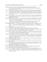
Contemporary masonry may take one of several forms. Structurally, it may be
divided into loadbearing and non-loadbearing construction. Walls may be of
single- or multi-wythe design. They may also be solid masonry, solid walls
of hollow units, or cavity walls. Finally, masonry may be reinforced or
unreinforced, and either empirically or analytically designed. Loadbearing
masonry supports its own weight as well as the dead and live loads of the
structure, and all lateral wind and seismic forces. Non-loadbearing masonry
also resists lateral loads, and veneers may support their own weight for the
full height of the structure, or be wholly supported by the structure at each
floor. Solid masonry is built of solid units or fully grouted hollow units in
multiple wythes with the collar joint between wythes filled with mortar or
grout. Solid walls of hollow units have open cores in the units, but grouted
collar joints. Cavity walls have two or more wythes of solid or hollow units
separated by an open collar joint or cavity at least 2 in. wide (see Fig. 1-4).
Masonry veneers are applied over non-masonry backing walls.
Empirical designs are based on arbitrary limits of height and wall thick-
ness. Engineered designs, however, are based on rational analysis of the loads
and the strength of the materials used in the structure. Standard calculations
are used to determine the actual compressive, tensile, and shear stresses, and
the masonry designed to resist these forces. Unreinforced masonry is still
sometimes designed by empirical methods, but is applicable only to low-rise
structures with modest loads. Unreinforced masonry is strong in compression,
but weak in tension and flexure (see Fig. 1-5). Small lateral loads and over-
turning moments are resisted by the weight of the wall. Shear and flexural
stresses are resisted only by the bond between mortar and units. Where
lateral loads are higher, flexural strength can be increased by solidly grouting
reinforcing steel into hollow unit cores or wall cavities wherever design
analysis indicates that tensile stress is developed. The cured grout binds the
masonry and the steel together to act as a single load-resisting element.
Contemporary masonry is very different from the traditional construc-
tion of earlier centuries. Its structural capabilities are still being explored as
continuing research provides a better understanding of masonry structural
behavior. Contemporary masonry buildings have thinner, lighter-weight,
more efficient structural systems and veneers than in the past, and struc-
tures designed in compliance with current code requirements perform well,
even in cases of significant seismic activity and extreme fire exposure.
1.5 COMMON CONCERNS Although there is continuing structural research aimed at making masonry
systems stronger, more efficient, and more economical, many of the concerns
1.4 CONTEMPORARY
MASONRY
8 Chapter 1 History and Development of Masonry Technology
Downloaded from Digital Engineering Library @ McGraw-Hill (www.digitalengineeringlibrary.com)
Copyright © 2004 The McGraw-Hill Companies. All rights reserved.
Any use is subject to the Terms of Use as given at the website.
HISTORY AND DEVELOPMENT OF MASONRY TECHNOLOGY
commonly expressed by both design professionals and contractors are
related to weather resistance. Moisture penetration and durability, in fact,
seem to be more significant day-to-day issues for most than structural
performance. Building codes, which have traditionally provided minimum per-
formance requirements only for structural and life safety issues, are now
beginning to address water penetration, weather resistance, and durability
issues for masonry as well as other building systems.
Contemporary masonry walls are more water permeable than traditional
masonry walls because of their relative thinness, and more brittle because of
the portland cement that is now used in masonry mortar. As is the case with
any material or system used to form the building envelope, the movement of
moisture into and through the envelope has a significant effect on the perfor-
mance of masonry walls. Contemporary masonry systems are designed, not
with the intent of providing a barrier to water penetration, but as drainage
walls in which penetrated moisture is collected on flashing membranes and
1.5 Common Concerns 9
Figure 1-4 Examples of masonry wall types.
Downloaded from Digital Engineering Library @ McGraw-Hill (www.digitalengineeringlibrary.com)
Copyright © 2004 The McGraw-Hill Companies. All rights reserved.
Any use is subject to the Terms of Use as given at the website.
HISTORY AND DEVELOPMENT OF MASONRY TECHNOLOGY
expelled through a series of weep holes. Higher-performance wall systems for
extreme weather exposures can be designed as pressure-equalized rain
screens, but at a higher cost than drainage walls. Design, workmanship, and
materials are all important to the performance of masonry drainage and rain
screen walls:
■
Mortar joints must be full
■
Mortar must be compatible with and well bonded to the units
■
Drainage cavity must be kept free of mortar droppings
■
Appropriate flashing material must be selected for the expected service life
of the building
■
Flashing details must provide protection for all conditions
■
Flashing must be properly installed
■
Weep holes must be properly sized and spaced
■
Weep holes must provide rapid drainage of penetrated moisture
With adequate provision for moisture drainage, masonry wall systems
can provide long-term performance with little required maintenance. The
chapters which follow discuss materials, design, and workmanship with an
eye toward achieving durability and weather resistance as well as adequate
structural performance in masonry systems.
10 Chapter 1 History and Development of Masonry Technology
Figure 1-5 Compressive, tensile, and flexural strength of masonry.
Downloaded from Digital Engineering Library @ McGraw-Hill (www.digitalengineeringlibrary.com)
Copyright © 2004 The McGraw-Hill Companies. All rights reserved.
Any use is subject to the Terms of Use as given at the website.
HISTORY AND DEVELOPMENT OF MASONRY TECHNOLOGY
11
2
RAW MATERIALS
AND MANUFACTURING
PROCESSES
The quality and characteristics of masonry products are directly and exclusively
determined by the raw materials and methods of manufacture used in their
production. A basic introduction to this aspect of masonry will aid in under-
standing the finished products and how they may best be used in specific
design applications.
Clay, the raw material from which brick, structural clay tile, and terra cotta
are made, is the most plentiful natural substance used in the production of any
building product. Clay is the end product of the chemical alteration over long
periods of time of the less stable minerals in rock. This chemical weathering
produces minute particles that are two-dimensional or flake-shaped. The
unique plastic characteristics of clay soils are a result of the enormous
amount of surface area inherent in this particle size and shape. The natural
affinity of clay soils and moisture results in cohesiveness and plasticity from
the surface tension of very thin layers of water between each of these minute
particles. It is this plasticity which facilitates the molding and shaping of
moist clay into usable shapes.
For the architect, the importance of understanding clay characteristics and
methods of manufacture is their relationship to finished appearance and physi-
cal properties. Color depends first on the composition of the raw material and
the quantitative presence of metallic oxides. Second, it is an indication of the
degree of burning to which the clay has been subjected. Lighter-colored units
(called salmons) for a given clay are normally associated with under-burning.
They may also be indicative of high porosity and absorption along with
decreased strength, durability, and resistance to abrasion. On the other hand,
2.1 CLAY MASONRY
Downloaded from Digital Engineering Library @ McGraw-Hill (www.digitalengineeringlibrary.com)
Copyright © 2004 The McGraw-Hill Companies. All rights reserved.
Any use is subject to the Terms of Use as given at the website.
Source: MASONRY DESIGN AND DETAILING
the very dark colored units (called clinkers) produced from the same clay result
from over-burning. This indicates that the units have been pressed and burned
to a very high compressive strength and abrasion resistance, with greatly
reduced absorption and increased resistance to freezing and thawing.
Most of the brick used in building construction falls between the
extremes of salmon and clinker brick. Since clay composition is the primary
determinant of brick color, lightness or darkness cannot be used as an
absolute indicator of physical properties for brick made from different raw
materials. It can, however, assist generally in the evaluation and selection of
brick to meet specific design or exposure requirements.
2.1.1 Clay Composition
Clays are basically compounds of silica and alumina with varying amounts of
metallic oxides and other minor ingredients and impurities. Metallic oxides
act as fluxes to promote fusion at lower temperatures, influence the range of
temperatures in which the material vitrifies, and give burned clay the neces-
sary strength for structural purposes. The varying amounts of iron, calcium,
and magnesium oxides also influence the color of fired clay.
Clays may be classified as either calcareous or non-calcareous. While
both are hydrous aluminum silicates, the calcareous clays contain around
15% calcium carbonate, which produces a yellowish color when fired. The non-
calcareous clays are influenced by feldspar and iron oxide. The oxide may
range from 2 to 25% of the composition, causing the clay to burn from a buff
to a pink or red color as the amount increases.
Any lime that is present in a clay must be finely crushed to eliminate
large lumps. Lime becomes calcined in the burning process and later slakes
or combines with water when exposed to the weather, so that any sizable
fragments will expand and possibly chip or spall the brick.
2.1.2 Clay Types
There are three different types of clay which, although they are similar in
chemical composition, have different physical characteristics. Surface clays,
shales, and fire clays are common throughout the world, and result from
slight variations in the weathering process.
Surface clay occurs quite close to the earth’s surface, and has a high
oxide content, ranging from 10 to 25%. Surface clays are the most accessible
and easily mined, and therefore the least expensive.
Shale is a metamorphic form of clay hardened and layered under natural
geologic conditions. It is very dense and harder to remove from the ground than
other clays, and as a result, is more costly. Like surface clay, shale contains a
relatively high percentage of oxide fluxes.
Fire clay is formed at greater depths than either surface clay or shale. It
generally has fewer impurities, more uniform chemical and physical proper-
ties, and only 2 to 10% oxides. The lower percentage of oxide fluxes gives fire
clay a much higher softening point than surface clay and shale, and the ability
to withstand very high temperatures. This refractory quality makes fire clay
best suited to producing brick and tile for furnaces, fireplaces, flue liners,
ovens, and chimney stacks. The low oxide content also causes the clay to
burn to a very light brown or light buff color, approaching white.
12 Chapter 2 Raw Materials and Manufacturing Processes
Downloaded from Digital Engineering Library @ McGraw-Hill (www.digitalengineeringlibrary.com)
Copyright © 2004 The McGraw-Hill Companies. All rights reserved.
Any use is subject to the Terms of Use as given at the website.
RAW MATERIALS AND MANUFACTURING PROCESSES
Clay is well suited to the manufacture of masonry products. It is plastic
when mixed with water, and easily molded or formed into the desired shapes; it
has sufficient tensile strength to maintain those shapes after the dies or molds
are removed; and its particles are ceramically fused at high temperatures.
2.1.3 Material Preparation
Brick plants commonly mine from several clay pits at a time. Since the raw
clay is not always uniform in quality and composition, two or more clays
from different pits or from remote locations within the same pit are blended
to minimize much of the natural variation in chemical composition and
physical properties. Blending produces a higher degree of product uniformity,
helps control the color of the units, and permits some latitude in providing
raw material suitable for specific types of brick or special product require-
ments. The clay is first washed to remove stones, soil, or excessive sand,
then crushed into smaller pieces, and finally ground to a powdered mix.
Particle size is carefully controlled so that only the finer material is taken to
storage bins or directly to the forming machine or pug mill for tempering
and molding.
2.1.4 Manufacturing
After preparation of the raw clay, the manufacture of fired brick is completed in
four additional stages: forming, drying, burning, and drawing and storage (see
Fig. 2-1). The basic process is always the same, and differences occur only in
the molding techniques. In ancient as well as more recent history, brick was
exclusively hand-made. Since brick-making machines were invented in the
late nineteenth century, however, most of the structural clay products manu-
factured in the United States are machine-made by one of three forming
methods: stiff-mud, soft-mud, or dry-press.
2.1.5 Forming
The first step in each forming method is tempering, where the clay is thor-
oughly mixed with a measured amount of water. The amount of water and
the desired plasticity vary according to the forming method to be used.
The stiff-mud extrusion method is used for more than 80% of the brick
manufactured in the United States. A minimum amount of water, generally
12 to 15% moisture by weight, is mixed with the dry clay to make it plastic.
After thorough mixing in a pug mill, the tempered clay goes through a de-airing
process which increases the workability and plasticity of the clay and produces
units with greater strength. The clay is then forced through a steel die in a
continuous extrusion of the desired size and shape, and at the same time, is
cored to reduce weight and to facilitate drying and burning. Automatic cutting
machines using thin wires attached to a circular steel frame cut the extruded
clay into pieces (see Fig. 2-2). Since the clay will shrink as it is dried and
burned, die sizes and cutter wire spacing must be carefully calculated to com-
pensate. Texturing attachments may be affixed to roughen, score, scratch, or
otherwise alter the smooth skin of the brick column as it emerges from the die
(see Fig. 2-3). After cutting, a clay slurry of contrasting color or texture may
also be applied to the brick surface to produce different aesthetic effects.
2.1 Clay Masonry 13
Downloaded from Digital Engineering Library @ McGraw-Hill (www.digitalengineeringlibrary.com)
Copyright © 2004 The McGraw-Hill Companies. All rights reserved.
Any use is subject to the Terms of Use as given at the website.
RAW MATERIALS AND MANUFACTURING PROCESSES
A conveyor belt moves the “green” or wet brick past inspectors, who
remove imperfect units and return them to the pug mill. Satisfactory units
are moved from the conveyor to dryer cars and stacked in a prescribed pat-
tern to allow free flow of air and kiln gases for burning. The stiff-mud process
produces the hardest and most dense of the machine-made bricks, and also
delivers the highest volume of production.
The soft-mud method of production is the oldest, and was used exclu-
sively up until the nineteenth century (see Fig. 2-4). All hand-made brick is
formed by this process even today. Only a few manufacturers still produce
genuine hand-made brick, but demand is increasing as more historic restora-
tion projects are undertaken.
14 Chapter 2 Raw Materials and Manufacturing Processes
Figure 2-1 Brick manufacturing process.
Downloaded from Digital Engineering Library @ McGraw-Hill (www.digitalengineeringlibrary.com)
Copyright © 2004 The McGraw-Hill Companies. All rights reserved.
Any use is subject to the Terms of Use as given at the website.
RAW MATERIALS AND MANUFACTURING PROCESSES
Automated machinery can accomplish soft-mud molding more uniformly
and efficiently than hand work, and is now widely used. The soft-mud
process is particularly suitable for clays which contain too much natural
water for the extrusion method. The clay is tempered to a 20 to 30% moisture
content (about twice that of the stiff-mud clays) and then pressed into wood-
en molds by hand or machine to form standard or special shapes. To prevent
the clay from sticking, the molds are lubricated with sand or water. The
resulting “sand-struck” or “water-struck” brick has a unique appearance
characterized by either a rough, sandy surface or a relatively smooth surface
with only slight texture variations from the individual molds (see Fig. 2-3). In
addition to having an attractive rustic appearance, soft-mud units are more
economical to install because less precision is required, and bricklayers can
usually achieve a higher daily production. Manufacturers often simulate the
look of hand-made brick by tumbling and roughening extruded brick.
The mortar bedding surfaces of sand-struck or sand-molded brick must
be brushed clean of loose sand particles so that mortar bond is not adversely
affected. Even if sand is not actually applied to the bed surfaces in the manu-
facturing process, stray particles along the edge of a unit can inhibit the critical
mortar-to-unit bond at the weathering face of a wall, creating an unwanted
increase in moisture penetration.
2.1 Clay Masonry 15
Figure 2-2 Wire-cutting extruded, stiff-mud brick. (Photo courtesy BIA.)
Downloaded from Digital Engineering Library @ McGraw-Hill (www.digitalengineeringlibrary.com)
Copyright © 2004 The McGraw-Hill Companies. All rights reserved.
Any use is subject to the Terms of Use as given at the website.
RAW MATERIALS AND MANUFACTURING PROCESSES
The dry-press method, although it produces the most accurately formed
units, is used for less than 0.5% of U.S made brick. Clays of very low natural
plasticity are required, usually with moisture contents of 10% or less. The
relatively dry mix is pressed into steel molds by hydraulic plungers exerting
a force of 500 to 1500 psi to form the unit.
2.1.6 Drying
Green clay units coming from the molding or cutting machines may contain
10 to 30% free moisture, depending on the forming process used. Before
16 Chapter 2 Raw Materials and Manufacturing Processes
Smooth Stippled
Matt Face—Horizontal Markings Sand-mold
Rugs Water-struck
Barks Sand-struck
Figure 2-3 Typical clay brick textures. (Photo courtesy BIA.)
Downloaded from Digital Engineering Library @ McGraw-Hill (www.digitalengineeringlibrary.com)
Copyright © 2004 The McGraw-Hill Companies. All rights reserved.
Any use is subject to the Terms of Use as given at the website.
RAW MATERIALS AND MANUFACTURING PROCESSES
burning can begin, most of this excess must be evaporated. The open sheds
once used for natural air drying were affected by weather conditions, and the
evaporation process took anywhere from 7 days to 6 weeks. Today, brick plants
use separate dryer kilns or chambers supplied with waste heat from the
exhaust of the firing kilns. Drying time takes only 24 to 48 hours, depending
on the original moisture content. Drying temperatures range from 100 to
400°F, but must be carefully regulated, along with humidity, to prevent sudden
changes which could crack or warp the units.
2.1.7 Glazing
Glazing is a highly specialized, carefully controlled procedure used in the
production of decorative brick. High-fired ceramic glazes are the most widely
used. The glaze is a blend of clays, ceramic frit, fluxes, and base metals
sprayed on the units before burning, and then subjected to normal firing
temperatures to fuse it to the clay body. Glazes with a higher flux content will
burn to a glossy finish, while more refractory mixes produce a matte glaze.
After the basic glass material is prepared, ceramic pigments are used to
stain it to the desired color. Cobalt, vanadium, chrome, tin, nickel, alumina,
and other metals are used singly or in combinations to produce standard,
2.1 Clay Masonry 17
Figure 2-4 Artist’s engraving of a colonial brick-making operation. (Courtesy BIA.)
Downloaded from Digital Engineering Library @ McGraw-Hill (www.digitalengineeringlibrary.com)
Copyright © 2004 The McGraw-Hill Companies. All rights reserved.
Any use is subject to the Terms of Use as given at the website.
RAW MATERIALS AND MANUFACTURING PROCESSES
custom, or color-matched blues, greens, ochers, pinks, lavenders, buffs,
grays, and blacks. Color consistency is easier to maintain with high-gloss
glazes, both within batches and between kiln runs.
Low-fired glazes are for colors which cannot be produced at high firing
temperatures such as bright red, bright yellow, burgundy, and orange. If
fired too hot, bright red, for instance, will craze or burn transparent because
the cadmium and lead in the glaze are unstable at high temperatures. The
glaze is applied after the brick has been burned to maturity, and then
requires a second firing at lower temperatures of 1300 to 1800°F. Low-fired
glazes are much more expensive because of the two-step process.
Clay coat glazes (sometimes called slip glazes) produce a dull, nonreflec-
tive, vitreously applied surface in softer tones than ceramic glazes. Salt glazes
are produced by applying a vapor of sodium-iron silicate to the brick while it
is at maximum firing temperature. The transparent finish shows the natural
color of the fired brick under a lustrous gloss.
Producing some ceramic glazes leaves contaminants in the kiln which
can affect the next batch of brick. The residue from ceramic glazes is also
classified by the Environmental Protection Agency as hazardous waste which
must be recovered for reuse or disposal.
2.1.8 Burning
After excess moisture has been evaporated from the clay units and desired
glazes, if any, have been applied, the bricks are ready for burning. This is one
of the most specialized and critical steps in the manufacture of clay products.
Burning is accomplished by controlled firing in a kiln to achieve ceramic
fusion of the clay particles and hardening of the brick. Since so many of the
properties of brick and clay tile depend on the method and control of firing,
the development over the years of more sophisticated kilns has been instru-
mental in improving the quality and durability of clay masonry.
Originally, bricks were cured by sun drying. This permitted hardening by
evaporation, but did not achieve the chemical fusion necessary for high
strength. High-temperature kiln firing of clay brick was done as early as 3500
B.C. Early scove kilns heated by wood fires were eventually replaced by beehive
kilns. The heat source was originally at the bottom of the kiln, and could not be
controlled effectively, so uneven firing resulted in hard-burned “clinker” brick
nearest the fire and soft, under-burned “salmon” brick at the top of the kiln.
Salmon bricks were sometimes used in unexposed locations such as filler cours-
es in multi-wythe walls, but clinker bricks were usually discarded. Builders in
colonial Williamsburg, Virginia, however, were fond of clinker brick and often
used shiny, black, overburned units as headers to create checkerboard patterns
with ordinary red brick. Tudor style homes of the early 1900s also used clinker
brick in the same way. Some manufacturers still produce and sell clinkers for
use, not only in restoring or renovating old buildings which used clinkers origi-
nally, but in new construction as well. The dark-colored, warped, or twisted
shapes provide textures which are unusual in brick walls.
Beehive kilns were later heated by more precisely controlled gas and oil
fires in separate fireboxes. Heat was circulated by a system of ducts from
both the bottom and the top of the kiln, which resulted in more uniform fir-
ing of the brick. However, the excessive time required for burning in a “peri-
odic” kiln of this nature yields only a limited quantity of bricks.
Most plants now use continuous straight-line tunnel kilns, with sophisti-
cated computer equipment for precisely controlled firing temperatures (see
Fig. 2-5). The clayware, which is stacked on flat rail cars for drying, is moved
18 Chapter 2 Raw Materials and Manufacturing Processes
Downloaded from Digital Engineering Library @ McGraw-Hill (www.digitalengineeringlibrary.com)
Copyright © 2004 The McGraw-Hill Companies. All rights reserved.
Any use is subject to the Terms of Use as given at the website.
RAW MATERIALS AND MANUFACTURING PROCESSES
into the first stage of the tunnel kiln, where it travels through various tem-
perature zones. A European manufacturer has recently patented a “rotary
circular kiln” that can reportedly save up to 30% on fuel consumption. Bricks
move through the kiln on a hydraulically controlled turntable. The system can
capture and reuse 70 to 75% of the waste heat compared to only about 45%
for tunnel kilns.
Burning consists essentially of subjecting brick units to gradually
increasing temperatures until fusion chemically alters the structure of the
clay. The burning process consists of six phases which are accomplished in
the dryer kiln and in the preheating, firing, and cooling chambers of the
burning kiln. The drying and evaporating of excess moisture are often called
the water-smoking stage. This initial preheat may be done in separate dryers
or, if high-fired glazes will not be added, in the forward section of the burn-
ing kiln. This exposure to relatively low temperatures of up to 400°F begins
the gradual, controlled heating process. Dehydration, or removal of the
remaining trapped moisture, requires anywhere from 300 to 1800°F, oxida-
tion from 1000 to 1800°F, and vitrification from 1600 to 2400°F. It is only
within this final temperature range that the silicates in the clay melt and fill
the voids between the more refractory materials binding and cementing them
together to form a strong, dense, hard-burned brick. The actual time and exact
temperatures required throughout these phases vary according to the fusing
characteristics and moisture content of the particular clay. Near the end of
the vitrification phase, a reducing atmosphere may be created in which there
is insufficient oxygen for complete combustion. This variation in the process
is called flashing, and is intended to produce different hues and shadings
from the natural clay colors. For example, if the clay has a high iron oxide
content, an oxygen-rich fire will produce a red brick. If the same clay is fired
in a reducing atmosphere with low oxygen, the brick will be more purple.
2.1 Clay Masonry 19
Figure 2-5 Tunnel kilns provide even heat distribution.
Downloaded from Digital Engineering Library @ McGraw-Hill (www.digitalengineeringlibrary.com)
Copyright © 2004 The McGraw-Hill Companies. All rights reserved.
Any use is subject to the Terms of Use as given at the website.
RAW MATERIALS AND MANUFACTURING PROCESSES
The final step in the firing of brick masonry is the cooling process. In a
tunnel kiln, this normally requires up to 48 hours, as the temperatures must be
reduced carefully and gradually to avoid cracking and checking of the brick.
2.1.9 Drawing and Storage
Removing brick from the kiln is called drawing. The loaded flatcars leave the
cooling chamber and are placed in a holding area until the bricks reach room
temperature. They are then sorted as necessary for size, chippage, and
warpage tolerances, bound into “cubes” equaling 500 standard-size bricks,
and either moved to storage yards or loaded directly onto trucks or rail cars
for shipment.
The development of modular concrete masonry was a logical outgrowth of the
discovery of portland cement, and was in keeping with the manufacturing
trends of the Industrial Revolution. Although the first rather unsuccessful
attempts produced heavy, unwieldy, and poorly adaptable units, the molding
of cementitious ingredients into large blocks promised a bright new industry.
With the invention and patenting of various block-making machines, unit
concrete masonry began to have a noticeable effect on building and construction
techniques of the late nineteenth and early twentieth centuries. Concrete
masonry today is made from a relatively dry mix of cementitious materials,
aggregates, water, and occasionally special admixtures. The material is molded
and cured under controlled conditions to produce a strong, finished block
that is suitable for use as a structural building element. Both the raw
materials and the method of manufacture influence strength, appearance,
and other critical properties of the block and are important in understanding
the diversity and wide-ranging uses of concrete masonry products.
2.2.1 Aggregates
The aggregates in concrete block and concrete brick account for as much as
90% of their composition. The characteristics of these aggregates therefore
play an important role in determining the properties of the finished unit.
Aggregates may be evaluated on the basis of (1) hardness, strength, and
resistance to impact and abrasion; (2) durability against freeze-thaw action;
(3) uniformity in gradation of particle size; and (4) absence of foreign particles
or impurities. A consistent blend of fine and coarse particle sizes is necessary
to produce a mixture that is easily workable and a finished surface that is
dense and resistant to absorption.
There are two categories of aggregates used in the manufacture of con-
crete masonry: lightweight aggregates and heavyweight aggregates (also called
normal-weight). Early concrete masonry units were, for the most part, made
with the same heavyweight aggregates as those used today. Well-graded
sand, gravel, crushed stone, and air-cooled slag are combined with other
ingredients to produce a block that is heavy, strong, and fairly low in water
absorption. Heavyweight aggregates for concrete masonry are covered in
ASTM C33, Standard Specification for Concrete Aggregates.
Efforts to make handling easier and more efficient led to the introduction
of lightweight aggregates. Pumice, cinders, expanded slag, and other natural
or processed aggregates are often used, and the units are sometimes marketed
under proprietary trade names. Testing and performance have proved that
lightweight aggregates affect more than just weight, however. Thermal, sound,
2.2 CONCRETE MASONRY
20 Chapter 2 Raw Materials and Manufacturing Processes
Downloaded from Digital Engineering Library @ McGraw-Hill (www.digitalengineeringlibrary.com)
Copyright © 2004 The McGraw-Hill Companies. All rights reserved.
Any use is subject to the Terms of Use as given at the website.
RAW MATERIALS AND MANUFACTURING PROCESSES
and fire resistance are also influenced, as well as color and texture. Lightweight
aggregates increase the thermal and fire resistance of concrete masonry, but
sound transmission ratings generally are lower because of reduced density.
Moisture absorption is also generally much higher with lightweight aggre-
gates. Lightweight aggregates are covered by ASTM C331, Standard
Specification for Lightweight Concrete Aggregates for Masonry Units.
In an effort to recycle materials, reduce landfill demand, and economize
production, some block manufacturers are now using crushed block as a por-
tion of the aggregate content in manufacturing new units. Broken units are
crushed and blended with new aggregate to save money on raw materials
and to give contractors an alternative means for disposing of construction
site debris. Currently about 50 to 60% of the block produced at some manu-
facturing plants uses at least some recycled material, and companies are
finding new ways to blend aggregates in order to use more recycled material.
Some federal agencies are already requiring certain percentages of recycled-
content materials in new construction projects.
Concrete masonry colors resulting from the mix of aggregate and
cement may range from white, to buff or brownish tones, to dull grays.
Special colors may be produced by the use of selected crushed stones or the
addition of special pigments. Color variation in units is affected by several
things. Aggregate gradation should be carefully controlled during manufac-
ture, but shipping of raw materials, particularly by rail, can cause separation
of fine surface material from coarse aggregate. The degree of separation and
resultant dust content varies from one shipment to the next, causing a varia-
tion in the color of the block (particularly with split face units). As ambient
temperatures rise during the day, moisture evaporates from the aggregate. If
the moisture content is not accurately monitored, particularly in hot cli-
mates, the drier aggregate effectively changes the water-cement ratio of the
mix within a single day’s production. Higher water-cement ratios produce
lighter-colored block. Temperature and moisture variations in the kiln affect
unit color, and units loaded first may also experience a slightly longer hydra-
tion period. Units which are air-dried can be significantly affected by
changes in ambient temperature and relative humidity.
Surface textures depend on the size and gradation of aggregates.
Classification of surface effects is only loosely defined as “open” or “tight,”
with either fine, medium, or coarse texture. Although interpretation of
these groups may vary, an open surface is generally characterized by
numerous large voids between the aggregate particles. A tight surface has
few pores or voids of the size easily penetrated by water or sound. Fine tex-
tures are smooth, and consist of small, very closely spaced granular particles.
Coarse textures are large grained and rough, and medium textures are, of
course, intermediate. Both coarse and medium textures provide better
sound absorption than the smoother faces, and are also recommended if the
units are to be plastered.
The American Society for Testing and Materials (ASTM) has developed
standards to regulate quality and composition. Within the limits of the
required structural properties of the masonry, the architect may select different
aggregates to serve other nonstructural functions required by building type,
occupant use, or aesthetics.
2.2.2 Cements
The cementitious material in concrete masonry is normally Type I, all-purpose
portland cement. Type III, high-early-strength cement, is sometimes used to
provide early strength and avoid distortion during the curing process. The
2.2 Concrete Masonry 21
Downloaded from Digital Engineering Library @ McGraw-Hill (www.digitalengineeringlibrary.com)
Copyright © 2004 The McGraw-Hill Companies. All rights reserved.
Any use is subject to the Terms of Use as given at the website.
RAW MATERIALS AND MANUFACTURING PROCESSES
air-entraining counterparts of these two cements (Types IA and IIIA) are
sometimes used to improve the molding and off-bearing characteristics of the
uncured units, and to increase resistance to weathering cycles. Air entrain-
ment, however, does cause some strength reduction.
2.2.3 Admixtures
Admixtures marketed chiefly for use in site-cast concrete have shown few
beneficial or desirable effects in the manufacture of concrete masonry. Air
entrainment facilitates compaction and the close reproduction of the contours
of the molds, but increased air content always results in lower compressive
strengths. Calcium chloride accelerators speed the hardening or set of the
units, but tend to increase shrinkage. Water repellent admixtures are com-
monly used in decorative architectural block intended for exterior exposures
without protective coatings. However, the bond between mortar and units
(and consequently the flexural strength of the wall) will be seriously impaired
unless the mortar is also treated with a chemically compatible admixture.
ASTM Standards do not permit the use of any admixtures in concrete masonry
without laboratory tests or performance records which prove that the addi-
tives are in no way detrimental to the performance of the masonry.
Architectural concrete masonry units are sometimes treated with an
integral water-repellent admixture during manufacture to resist soil accu-
mulations and to decrease surface water absorption. Some research indi-
cates that calcium stearate–based products are more effective in creating
hydrophobic surfaces than those based on oleic/linoleic acid chemistries, and
are also less likely to leach out of the masonry. An integral water repellent
which lasts the life of the masonry will provide more economical perfor-
mance than a surface-applied water repellent which must be reapplied
every few years. Whenever an integral water repellent is used in a concrete
masonry product, compatibility and bond with mortar must be considered
because the bonding characteristics of the unit are affected. CMU products
that have been treated with an integral water repellent require mortar that
has a compatible chemical admixture to promote better bond.
Special colors can be produced by using pure mineral oxide pigments, but
many factors affect color consistency. Even in natural block, color variations
can be caused by the materials, processing, curing, and weathering. In inte-
grally colored units, such variations may be magnified. Natural aggregate
colors are more durable, and more easily duplicated in the event of future
additions to a building.
2.2.4 Manufacturing
Concrete masonry manufacturing consists of six phases: (1) receiving and
storing raw materials, (2) batching and mixing, (3) molding unit shapes, (4)
curing, (5) cubing and storage, and (6) delivery of finished units (see Fig. 2-6).
2.2.5 Material Preparation
Materials are delivered in bulk quantities by truck or rail. Aggregates are
stored separately and later blended to produce different block types. Mixes will
vary depending on aggregate weight, particle characteristics, and water absorp-
22 Chapter 2 Raw Materials and Manufacturing Processes
Downloaded from Digital Engineering Library @ McGraw-Hill (www.digitalengineeringlibrary.com)
Copyright © 2004 The McGraw-Hill Companies. All rights reserved.
Any use is subject to the Terms of Use as given at the website.
RAW MATERIALS AND MANUFACTURING PROCESSES
tion properties. Ingredients must be carefully regulated so that consistency
in texture, color, dimensional tolerances, strength, and other physical proper-
ties is strictly maintained. Batching by weight is more common than volume
proportioning.
The mixes normally have a low water-cement ratio, and are classified
as zero-slump concrete. Special high-strength units are made with more
cement and water, but still have no slump. In the production of some slump
block units, the batching is changed so that the mix will slump within con-
trolled limits when the unit is removed from its mold. The soft roll in texture
is intended to produce the appearance of a handmade adobe.
2.2.6 Forming
Early block production consisted of hand-tamping the concrete mix into
wooden molds. A two-man team could turn out about 80 blocks a day. By the
mid-1920s, automatic machines could produce as many as 3000 blocks a day.
Today, units are molded with a combination of mechanical vibration and
hydraulic pressure, and production is typically in the neighborhood of 1000
units per hour.
2.2.7 Curing
Freshly molded blocks are lightly brushed to remove loose aggregate particles,
then moved to a kiln or autoclave for accelerated curing.
A normal 28-day concrete curing cycle is not conducive to the mass
production of unit masonry. Experiments in accelerated steam curing were
conducted as early as 1908. In addition to hastening the hydration process,
steam curing also increases compressive strength, helps control shrinkage,
and aids in uniformity of performance and appearance. Both high-pressure
and low-pressure curing are used in the industry.
Most of the block manufactured in the United States is produced by
low-pressure steam curing. The first phase is the holding or preset period of 1
to 3 hours. The units are allowed to attain initial hardening at normal temper-
atures of 70 to 100°F before they are exposed to steam. During the heating
2.2 Concrete Masonry 23
Figure 2-6 Concrete masonry manufacturing process.
Downloaded from Digital Engineering Library @ McGraw-Hill (www.digitalengineeringlibrary.com)
Copyright © 2004 The McGraw-Hill Companies. All rights reserved.
Any use is subject to the Terms of Use as given at the website.
RAW MATERIALS AND MANUFACTURING PROCESSES
period, saturated steam is injected to raise the temperature to a maximum of
190°F. The exact time duration and temperature span recommended by the
American Concrete Institute (ACI) depend on the composition of the cementi-
tious materials and the type of aggregate used. Once maximum temperature
is reached, the steam is shut off and a soaking period begins. Blocks are held
in the residual heat and moisture for 12 to 18 hours or until the required
compressive strengths are developed. An accelerated drying period may also
be used, with the temperature in the kiln raised to evaporate moisture.
The entire cycle is generally accomplished within 24 hours.
Compressive strengths of 2- to 4-day-old units cured by low-pressure steam
are approximately 90% of ultimate strength compared with only 40% for
blocks of the same age cured by 28-day moist sprinkling. Steam-cured units
are also characterized by a generally lighter color.
A variation of the low-pressure steam method adds a carbonation phase
in which carbon dioxide is introduced into the drying atmosphere to cause
irreversible shrinkage. Preshrinking decreases volume changes caused by
atmospheric moisture conditions and reduces shrinkage cracking in the wall.
Carbonation also increases tensile and compressive strength, hardness, and
density of the block.
High-pressure steam curing improves the quality and uniformity of con-
crete masonry, speeds production, and lowers manufacturing costs. Curing
takes place in an autoclave kiln 6 to 10 feet wide and as much as 100 feet
long (see Fig. 2-7).
A typical high-pressure curing cycle consists of four phases: preset, tem-
perature rise, constant temperature and pressure, and rapid pressure
release. The low-heat preset period hardens the masonry sufficiently to with-
stand the high-pressure steam. The temperature rise period slowly brings both
24 Chapter 2 Raw Materials and Manufacturing Processes
Figure 2-7 Loading racks of fresh units into an autoclave for
high-pressure steam curing. (Photo courtesy PCA.)
Downloaded from Digital Engineering Library @ McGraw-Hill (www.digitalengineeringlibrary.com)
Copyright © 2004 The McGraw-Hill Companies. All rights reserved.
Any use is subject to the Terms of Use as given at the website.
RAW MATERIALS AND MANUFACTURING PROCESSES
pressure and temperature within the autoclave to maximum levels, where
they remain constant for 5 to 10 hours. Temperature is actually the critical
curing factor. Pressure is used as a means of controlling steam quality. Rapid
pressure release or “blow-down” causes quick moisture loss from the units with-
out shrinkage cracks. For normal-weight aggregates, the cycle produces rela-
tively stable, air-dry blocks soon after removal from the autoclave. Lightweight
blocks may require additional time to reach this same air-dry condition.
Blocks cured by high-pressure autoclaving undergo different chemical
reactions from those cured at low pressure. They are more stable and less sub-
ject to volume change caused by varying moisture conditions. The improved
dimensional stability reduces shrinkage cracking in completed wall assemblies.
2.2.8 Surface Treatment
Concrete blocks are sometimes finished with ceramic, organic, or mineral
glazes. These special finishes are applied after curing, and then subjected to
heat treatment. The facings vary from epoxy or polyester resins to specially
treated glass silica sand, colored ceramic granules, mineral glazes, and
cementitious finishes. The treated surfaces are resistant to water penetration,
abrasion, and cleaning compounds, and are very durable in high-traffic areas.
Surface textures are applied to hardened concrete blocks in a number of
ways. Grinding the unit face produces a smooth, polished finish that highlights
the aggregate colors (see Fig. 2-8). Ground faces can be supplementally treated
with a wax or clear sealer. Sandblasting a block face exposes the underlying
aggregate, adding color, texture, and depth. Split-faced units are produced by
splitting ordinary blocks lengthwise. Solid units produce a rough stone appear-
ance, while cored units are used to make split-ribbed block (see Fig. 2-9).
2.2 Concrete Masonry 25
Figure 2-8 Concrete blocks face-ground to
expose natural aggregate col-
ors.
Downloaded from Digital Engineering Library @ McGraw-Hill (www.digitalengineeringlibrary.com)
Copyright © 2004 The McGraw-Hill Companies. All rights reserved.
Any use is subject to the Terms of Use as given at the website.
RAW MATERIALS AND MANUFACTURING PROCESSES