Tài liệu về Role SPAJ 140c
Bạn đang xem bản rút gọn của tài liệu. Xem và tải ngay bản đầy đủ của tài liệu tại đây (738.94 KB, 68 trang )
Ser.No.
n
=
n
=
SPAJ 140 C
aux
SPCJ 4D29
REGISTERS
OPER.IND.
0000
0
1
2
3
4
5
6
7
8
n
/
L3
n
/
L1
n
/
L2
max (15min)
on
/
1
2
3
4
5
6
7
8
>
START
>
TRIP
>
>
TRIP
>
>
START
>
o
START
>
>
o
START
>
o
TRIP
>
>
o
TRIP
9
%
)(
>
%
)(
>>
()
>
o
%
(
o
)
%
>>
CBFP9
t
t
t
t
[]
[]
[]
[]
I
0074A
I
(
)
I
(
)
o
I
I
I
I
I
I
I
I
I
I
I
I
I
I
I
I
I
I
I
I
I
n
I
/
I
80 265V
~
–
18 80V
–
5A1A
1A 5A
2
5
U
f
n
= 50Hz
60Hz
RS 611 006 -
[
SGR
SGB
SGF
SPCJ 4D29
TRIP
PROGRAM
RESET
STEP
L1 L2 L3
0
IRF
3
>
I
I
I
II
I
>
n
I
I
/
k
s
>
t
]
n
>
>
I
I
/
s
>
>
[]
t
s
>
k
[]
t
n
0
>
I
I
/
s
>
>
o
t
[]
n
>
>
o
I
/
I
0012A
0
0
SPAJ 140 C
Overcurrent and earth-fault relay
User´s manual and Technical description
2
SPAJ 140 C
Combined overcurrent
and earth-fault relay
Contents
Features 2
Application 2
Description of operation 3
Connections (modified 2003-09) 4
Signal diagram 7
Signal abbreviations 7
Start and operation indicators 8
Power supply and output relay module 9
Technical data (modified 2007-02) 10
Maintenance and repairs 13
Spare parts 13
Dimensions and instructions for mounting 14
Order information 14
The complete manual for the relay SPAJ 140 C contains the following submanuals:
General relay description for SPAJ 140 C 1MRS 750629
General characteristics of D type relay modules 1MRS 750066-MUM EN
Combined overcurrent and earth-fault relay module
type SPCJ 4D29 1MRS 750119
Features
Three-phase, low-set phase overcurrent unit
with definite time or inverse definite minimum
time (IDMT) characteristic
Three-phase, high-set phase overcurrent unit
with instantaneous or definite time function
Low-set, non-directional earth-fault unit with
definite time or inverse definite minimum time
(IDMT) characteristic
High-set, non-directional earth-fault unit with
instantaneous or definite time function
Built-in breaker failure protection function
Two heavy-duty and four light-duty output
relays with field-selectable configuration
Extensive data communication capabilities over
built-in serial port
Outstanding design flexibility for easy selection
of appropriate operation schemes for different
applications
Numerical display of setting values, measured
values, memorized fault values, fault codes etc.
Enhanced system reliability and availability due
to continuous hardware and software self-super-
vision with auto-diagnosis
Powerful software support for setting and
parametrizing of the relay and for recording of
relay parameters with a portable PC.
The combined overcurrent and earth-fault relay
SPAJ 140 C is intended to be used for the
selective short-circuit and earth-fault protection
of radial feeders in solidly earthed, resistance
earthed or impedance earthed power systems.
The integrated protection relay includes a phase
overcurrent unit and an earth-fault unit with
flexible tripping and signalling facilities. The
overcurrent and earth-fault relays can also be
used inother applications requiring single-, two-
or three-phase overcurrent protection and non-
directional earth-fault protection. The com-
bined overcurrent and earth-fault relay also fea-
tures circuit breaker failure protection.
Application
1MRS 750629
Issued 1997-01-30
Modified 2007-02-26
Version D
Data subject to change without notice
3
Description of
operation
The combined overcurrent and earth-fault relay
is a secondary relay to be connected to the
current transformers of the protected object.
The three-phase overcurrent unit and the earth-
fault unit continuously measure the phase cur-
rents and the neutral current of the protected
object. On detection of a fault the relay starts,
trips the circuit breaker, initiates auto-reclosing,
provides alarm, records fault data etc. in accord-
ance with the application and the configured
relay functions.
When the phase current exceeds the set start
current of the low-set stage I>, the overcurrent
unit starts delivering a start signal after a preset
~60 ms start time. When the set operate time at
definite time operation or the calculated operate
time at inverse time operation elapses, the over-
current unit operates. In the same way the high-
set stage I>> of the overcurrent unit starts deliv-
ering a start signal after a preset ~40 ms start
time, when the set start current is exceeded.
When the set operate time elapses, the overcur-
rent unit operates.
When the earth-fault current exceeds the set
start current of the low-set stage I
0
>, the earth-
fault unit starts delivering a start signal after a
preset ~60 ms start time. When the set operate
time at definite time operation or the calculated
operate time at inverse time operation elapses,
the earth-fault unit operates. In the same way
the high-set stage I
0
>> of the earth-fault unit
starts delivering a start signal after a preset ~40
ms start time, when the set start current is
exceeded. When the set operate time elapses, the
earth-fault unit operates.
The low-set stage of the overcurrent unit and the
low-set stage of the earth-fault unit may be given
definite time or inverse definite minimum time
(IDMT) characteristic. When the IDMT char-
acteristic is chosen six time/current curves are
available. Four of the curves comply with the BS
142 and IEC 60255 and are named "Normal
inverse", "Very inverse", "Extremely inverse"
and "Long-time inverse". The two additional
inverse time curves called the "RI-curve" and
the "RXIDG-curve" are also provided.
By appropriate configuration of the output relay
matrix, the start signals of the overcurrent and
earth-fault units are obtained as contact func-
tions. The start signals can be used for blocking
co-operating protection relays, for signalling
and for initiating auto-reclosing.
The relay includes one external binary input,
which is controlled by an external control volt-
age. The function of the control input is deter-
mined by selector switches in the protection
relay module. The control input can be used for
blocking the operation of one or more protec-
tion stages, for resetting a latched output relay in
the manual reset mode or for enforcing a new set
of relay setting parameters by remote control.
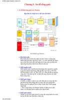
Fig. 1. Protection functions of the combined overcurrent and earth-fault relay type SPAJ 140 C.
THREE PHASE DEFINITE TIME
OR INVERSE TIME LOW-SET
OVERCURRENT PROTECTION
SERIAL COMMUNICATION PORT
TRIP
SIGNAL 1
SERIAL I/O
IL1
IL2
IL3
Io
BLOCKING
OR RESET
THREE PHASE INSTANTANEOUS
OR DEFINITE TIME HIGH-SET
OVERCURRENT PROTECTION
INSTANTANEOUS OR DEFINITE
TIME HIGH-SET EARTH-FAULT
PROTECTION
REMOTE RESET, REMOTE SETTING
CONTROL OR BLOCKING INPUT FOR
THE DIFFERENT CURRENT STAGES
SIGNAL 2
START 1
IRF
START 2
CIRCUIT BREAKER FAILURE
PROTECTION
DEFINITE TIME OR INVERSE TIME
LOW-SET EARTH-FAULT
PROTECTION
51
50
51 N
51BF
50 N
4
Connections
(modified 2003-09)
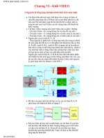
Fig. 2. Connection diagram for the combined overcurrent and earth-fault relay type SPAJ 140 C.
6162
SPAJ 140 C
63
25 26 27123456 789
1 A
5 A
L1
L2
L3
70 71 72
0
65 66
U
+ (~)
- (~)
3I>
3I>>
Io>
Io>>
IRF
I/O
68 6977 78
IRF SIGNAL 2
-
+
TRIP
74 75
START 1
80 81
1011
SGB/1
SGB/2
SGB/3
SGB/4
SGB/6
SGB/7
SGB/5
LATCHING
SIGNAL 1START 2
RESET
I
-
I
0
+
+
+
B
+
C
+
F
+
E
+
D
+
A
U1
1
1
T2
T4
T6
T8
T1
T3
T5
T7
RC SETTINGS
SGB/8
SGF/4
0.1 1s
SGR2/8
SGR1/6
SGR1/8
SGR1/2
SGR1/4
U3
TRIP
R
U2
U1
T9
TS2SS3SS2SS1TS1
SPA-ZC_
Rx Tx
SERIAL
PORT
+-
1 A
5 A
1 A
5 A
1 A
5 A
SGR2/6
SGR2/4
SGR2/2
1
SGR2/7
SGR2/5
SGR2/3
SGR2/1
1
SGR1/7
SGR1/5
SGR1/3
SGR1/1
1
SGR3/8
SGR3/7
SGR3/6
SGR3/5
SGR3/4
SGR3/3
SGR3/2
SGR3/1
aux
~
EXTERNAL
CONTROL
5
U
aux
Auxiliary voltage
A, B, C, D, E, F Output relays
IRF Self-supervision
SGR Switchgroups for the configuration of the output relays
SGB Switchgroup for the configuration of the blocking or control signal
TRIP Trip output relay
SIGNAL 1 Signal on operation of the overcurrent unit
SIGNAL 2 Signal on operation of the earth-fault unit
START 1 Starting or auxiliary trip signal as selected with switchgroup SGR3
START 2 Start signal of the low-set overcurrent stage I>
U1 Overcurrent and earth-fault relay module SPCJ 4D29
U3 Input module SPTE 4E1
U2 Power supply and output relay module SPTU 240 R1 or SPTU 48 R1
T1…T9 Start and operation indications
SERIAL PORT Serial communication port
SPA-ZC_ Bus connection module
Rx/Tx Receiver bus terminal (Rx) and transmitter bus terminal (Tx) of the bus
connection module
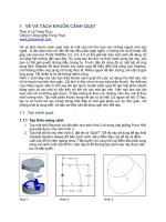
Fig. 3. Terminal arrangement of the overcurrent and earth-fault relay type SPAJ 140 C.
68
69
77
78
80
81
Made in Finland
1
2
3
4
5
6
7
8
9
25
26
27
61
62
63
65
66
74
75
70
71
72
10
11
Serial Port
SPA
6
The energizing currents of the overcurrent unit
are connected to terminals 1-2, 4-5 and 7-8,
when the rated current of the CT secondary
circuits is I
n
= 5 A. When the rated current of the
CT secondary circuits is I
n
= 1 A, terminals 1-3,
4-6 and 7-9 are used. The relay can also be used
in single-phase or two-phase applications sim-
ply by leaving one or two energizing inputs
unoccupied. In single-phase applications the
same energizing current can be routed through
two energizing inputs, which may increase the
operating speed of the overcurrent unit, espe-
cially at instantaneous operation.
The energizing current for the earth-fault unit is
connected to terminals 25-26 when the rated
current I
n
= 5 A and to terminals 25-27 when
the rated current I
n
= 1 A.
The control input 10-11 can be used in three
different ways, i) as control input for an external
blocking signal, ii) as the control input for
unlatching the trip relay, or iii) as the control
input for the remote control of relay settings.
The requested function is selected by means of
switches switchgroup SGB in the main menu of
the protection relay module.
The auxiliary supply voltage of the relay is
connected to terminals 61-62. At d.c. supply
the positive lead is connected to terminal 61.
The level of the voltage to be applied to the
terminals depends on the type of power supply
and output relay module inserted in the relay.
For further details see the description of the
power supply module. The permitted auxiliary
voltage range of the relay is marked on the relay
front panel.
Output relay A is a heavy-duty trip relay capable
of controlling most circuit breakers. The oper-
ate signals of the different protection stages are
routed to the trip relay with switches 2,4,6 and
8 of switchgroup SGR1. On delivery from the
factory all the protection stages are routed to the
trip relay. A latching of the output relay A can
be selected with switches 6 and 7 of switchgroup
SGB.
Output relays B and C can be used for signalling
on operation of the relay module. The signals to
be routed to the output relays B and C are
selected with switches1 8 of switchgroup SGR2.
The switch matrixes for routing operate signals
to the output relays B and C are identical.
Normally output relay B is used for signalling on
operation of the overcurrent unit and C for
signalling on operation of the earth-fault unit.
This is also the default setting of the relay on
delivery from the factory.
The start signals of the protection stages of the
relay are routed to output relay D. The signals to
be routed to output relay D are selected by
means of switches 1, 3, 5 and 7 of switchgroup
SGR1, which is a software switchgroup found in
the main menu of the protection relay module.
The start signals of the low-set and high-set stage
of the overcurrent unit are selected with switches
1 and 3, and the start signals of the high-set and
low-set stage of the earth-fault unit with switches
5 and 7.
The output relay E is a heavy-duty relay as
output relay A. It can be controlled by the start
and operate signals of the protection stages.
Output relay E is also used a trip relay for the
circuit breaker failure protection (CBFP), when
the CBFP protection is used. In this case the trip
signal can be used either to control a circuit
breaker upstreams or to control a second trip
coil on the main circuit breaker to increase the
redundancy of the circuit breaker.
Output relay F functions as output relay for the
self-supervision system of the protection relay.
The F relay is energized under normal operating
conditions and contact gap 70-72 is closed. If a
fault is detected by the self-supervision system,
or on loss of auxiliary supply, the output relay
drops off and the NO contact 71-72 closes.
By means of bus connection modules type
SPA -ZC17 and SPA-ZC21 the relay connects
to the fibre-optic SPA bus via a 9-pole, D-type
subminiature connector located at the rear panel
of the relay. The terminals of the fibre-optic
cables are connected to the counter terminals Rx
(receiver) and Tx (transmitter) of the bus con-
nection module. The fibre-optic cables are linked
from one relay to another and to the substation
level communication unit, for instance type
SRIO 1000M.
7
be configured to obtain the required protection
functions.
SGR3 / 6
SGR1 / 8
IL1
IL2
IL3
SGR3 / 1
SGR1 / 1
SGR3 / 2
SGR2 / 1
SGR2 / 2
SGR1 / 2
SGR3 / 3
SGR1 / 3
SGR3 / 4
SGR2 / 3
SGR2 / 4
SGR1 / 4
SGR3 / 5
SGR1 / 5
SGR2 / 5
SGR2 / 6
SGR1 / 6
SGR3 / 7
SGR1 / 7
SGR3 / 8
SGR2 / 7
SGR2 / 8
I>
I>>
t>>
t>, k
to>, ko
Io>
to>>
Io>>
Io
BS
SGB / 1
SGB / 2
SGB / 3
SGB / 4
SGB / 5
SGB / 8
REMOTE SETTINGS
RELAY RESET
1
SGB / 6
RESET+
PROGRAM
1
SGB / 7
RESET+
PROGRAM
1
1
1
SGF1 / 4
SS1
SS2
SPCJ 4D29
TS1
TS2
SS3
RESET
TRIP
0.1 1s
A
B
C
D
F
IRF
E
START 1
START 2
SIGNAL 1
SIGNAL 2
TRIP
IRF
(AR2)
(AR1)
(AR3)
SGF2 / 8
SGF2 / 7
SPTU ___R1
REDUCED BLOCK DIAGRAM
Fig. 4. Signal diagram of the combined overcurrent and earth-fault relay type SPAJ 140 C
The functions of the blocking and start signals
are selected with the switches of switchgroups
SGF, SGB and SGR. The checksums of the
switchgroups, are found in the setting menu of
the protection relay module. The functions of
the different switches are explained in detail in
the user´s manual of the protection relay mod-
ule SPCJ 4D29.
Signal diagram
The figure below schematically illustrates how
the start, trip, control and blocking signals can
I
L1
, I
L2
, I
L3
Energizing current of phase L1, L2 and L3
I
0
Neutral current (Residual current)
BS Blocking or control signal
SS1 Start signal 1
SS2 Start signal 2
SS3 Start signal 3
TS1 Operate signal 1 (Trip signal 1)
TS2 Operate signal 2 (Trip signal 2)
BS Blocking signal
AR1 3 Auto-reclose start signals (not in use in relay SPAJ 140 C)
IRF Internal relay failure
SGF Switchgroup for functions
SGB Switchgroup for blockings
SGR Switchgroup for relay configuration
Signal
abbreviations
8
Operation
indicators
A) The indicator TRIP is lit when one of the
protection stages operates. When the protec-
tion stage resets, the red indicator remains lit.
B) If the display is dark when one of the protec-
tion stages I>, I>>, I
0
> or I
0
>> operates, the
faulty phase or the neutral circuit is indicated
with a yellow LED. If, for instance, the TRIP
indicator glows red, and the indicators I
L1
and I
L2
at the same time are lit, overcurrent
has occurred on phase L1 and L2.
C) Besides being a code number at data presen-
tation, the leftmost red digit in the display
serves as a visual operation indicator. An
operation indicator is recognized by the fact
that the red digit alone is switched on. The
following table named OPERATION IND.
on the relay front panel is a key to the
function code numbers used.
Ser.No.
n
=
n
=
SPAJ 140 C
aux
SPCJ 4D29
REGISTERS
OPER.IND.
0000
0
1
2
3
4
5
6
7
8
n
/
L3
n
/
L1
n
/
L2
max
(15min)
on
/
1
2
3
4
5
6
7
8
>
START
>
TRIP
>
>
TRIP
>
>
START
>
o
START
>
>
o
START
>
o
TRIP
>
>
o
TRIP
9
%
)(
>
%
)(
>>
()
>
o
%
(
o
)
%
>>
CBFP
9
t
t
t
t
[]
[]
[]
[]
I
0074A
I
(
)
I
(
)
o
I
I
I
I
I
I
I
I
I
I
I
I
I
I
I
I
I
I
I
I
I
n
I
/
I
80 265V
~
–
18 80V
–
5A1A
1A 5A
2
5
U
f
n
= 50Hz
60Hz
RS 611 006 -
[
SGR
SGB
SGF
SPCJ 4D29
TRIP
PROGRAM
RESET
STEP
L1 L2 L3
0
IRF
3
>
I
I
I
II
I
>
n
I
I
/
k
s
>
t
]
n
>
>
I
I
/
s
>
>
[]
t
s
>
k
[]
t
n
0
>
I
I
/
s
>
>
o
t
[]
n
>
>
o
I
/
I
0012A
0
0
Indication Explanation
1 I> START = The low-set stage I> of the overcurrent unit has started
2 I> TRIP = The low-set stage I> of the overcurrent unit has operated
3 I>> START = The high-set stage I>> of the overcurrent unit has started
4 I>> TRIP = The high-set stage I>> of the overcurrent unit has operated
5I
0
> START = The low-set stage I
0
> of the earth-fault unit has started
6I
0
> TRIP = The low-set stage I
0
> of the earth-fault unit has operated
7I
0
>> START = The high-set stage I
0
>> of the earth-fault unit has started
8I
0
>> TRIP = The high-set stage I
0
>> of the earth-fault unit has operated
9 CBFP = Circuit breaker failure protection has operated
D) The TRIP indications persist when the pro-
tection stage returns to normal. The indica-
tor is reset by pushing the RESET/STEP
push-button.
Further, the indicators may be reset via the
external control input 10-11 by applying a
control voltage to the input, provided switch
SGB/8 is in position 1.
The basic protection relay functions are not
depending on the state of the operation indica-
tors, reset or non-reset. The relay is permanently
operative.
If a protection stage starts, but not operates,
because the energizing quantity goes below the
set start current before the operate time circuit
has timed out, the start indicators are normally
automatically switched off. However, by means
of the switches SGF2/1…4 the start indications
may be made persistant which means that they
are to be manually reset by pushing the RESET/
STEP push-button. The persistent indications
are obtained through the following switch set-
tings.
SGF2/1 = 1 manual reset of I> start indication
SGF2/2 = 1 manual reset of I>> start indication
SGF2/3 = 1 manual reset of I
0
> start indication
SGF2/4 = 1 manual reset of I
0
>> start indication
On delivery of the relay from the factory the
switches SGF2/1…4 are preset at 0.
E) Shortly after the internal self-supervision
system has detected a permanent relay fault
the red IRF indicator is switched on and the
output relay of the self-supervision system
operates. Further, in most fault situations an
autodiagnostic fault code is shown in the
display. The fault code is composed of a red
figure 1 and a green code number which
indicates fault type. The fault code persists
until the STEP/RESET push-button is
pressed. When a fault code appears on the
display, the code number should be recorded
for statistical and maintenance purposes.
9
Power supply
and output relay
module
To be able to operate the relay needs a secured
auxiliary voltage supply. The power supply
module forms the voltages required by the pro-
tection relay module and the auxiliary relays.
The withdrawable power supply and output
relay module is located behind the system front
panel, which is fixed by means of four cross-
slotted screws. The power supply and output
relay module contains the power supply unit, all
output relays, the control circuits of the output
relays and the electronic circuitry of the external
control inputs.
The power supply and output relay module can
be withdrawn after removing the system front
panel. The primary side of the power supply
module is protected with a fuse, F1, located on
the PCB of the module. The fuse size is 1 A
(slow).
The power supply unit is a pulse-width modu-
lated (PWM) dc/dc converter with galvanically
isolated primary and secondary sides. It forms
the dc secondary voltages required by the pro-
tection relay module; that is +24 V, ±12 V and
+8 V. The output voltages ±12 V and +24 V are
stabilized in the power supply module, while the
+5 V logic voltage required by the protection
relay module is stabilized in the protection relay
module.
1 A slow
+8V
+12V
-12V
+24V
Uaux
80 265 V ac & dc
18 80 V dc
Unstabilized logics
voltage
Operation amplifier
voltage
Output relay coil
voltage
Fig. 5.Voltage levels of the power supply unit
A green LED indicator U
aux
on the system front
panel is lit when the power supply module is in
operation. The supervision of the voltages sup-
plying the electronics is located in the protec-
tion relay module. If a secondary voltage differs
too much from its rated value, a self-supervision
alarm will be generated. An alarm is also issued
when the power supply module is withdrawn
from the relay case, or on loss of auxiliary supply.
There are two versions of power supply and
output relay modules available. For both types,
the secondary sides and the relay configurations
are identical, but the input voltage ranges differ.
Insulation test voltage between the primary and
secondary side and the protective earth
2 kV, 50 Hz, 1 min
Rated power P
n
5 W
Voltage ranges of the power supply modules:
- SPTU 240 R1 U
aux
= 80 265 V dc/ac
- SPTU 48 R1 U
aux
= 18 80 V dc
The SPTU 240 R1 module can be fed from
either an ac source or a dc source. SPTU 48 R1
is designed for dc supply only. The permitted
auxiliary voltage range of the relay is marked on
the relay system front panel.
10
Energizing inputs
Rated current I
n
1 A 5 A
Thermal withstand capability
- continuously 4 A 20 A
- for 1 s 100 A 500 A
Dynamic current withstand, half-wave value 250 A 1250 A
Input impedance <100 mΩ <20 mΩ
Rated frequency f
n
, on request 50 Hz or 60 Hz
Output contact ratings
Tripping contacts
Terminals 65-66, 74-75
Rated voltage 250 V dc/ac
Continuous carry 5 A
Make and carry for 0.5 s 30 A
Make and carry for 3.0 s 15 A
Breaking capacity for dc, when the trip circuit
time-constant L/R ≤ 40 ms, at 48/110/220 V dc 5 A/3 A/1 A
Signalling contacts
Terminals 70-71-72, 68-69, 77-78, 80-81
Rated voltage 250 V dc/ac
Continuous carry 5 A
Make and carry for 0.5 s 10 A
Make and carry for 3.0 s 8 A
Breaking capacity for dc, when the signal circuit
time-constant L/R ≤ 40 ms, at 48/110/220 V dc
signal circuit voltage 1 A/0.25 A/0.15 A
External control inputs
Blocking, remote reset or remote setting input 10-11
Control voltage level 18 265 V dc or 80 265 V ac
Control current of activated input 2…20 mA
Power supply and output relay module
Supply and output relay module, type SPTU 240 R1 80 265 V dc/ac
Supply and output relay module, type SPTU 48 R1 18 80 V dc
Power consumption under quiescent/operating
conditions ~4 W/ ~6 W
Technical data
(modified 2002-04)
11
Overcurrent unit of SPCJ 4D29
Low-set overcurrent stage I> *
Start current **
- at definite time characteristic 0.5 5.0 x I
n
- at inverse time characteristic *** 0.5…2.5 x I
n
Time/current characteristic
- definite time characteristic
- operate time t> 0.05 300 s
- inverse definite minimum time (IDMT)
characteristic as per IEC 60255-3 and BS 142 Extremely inverse
Very inverse
Normal inverse
Long-time inverse
- special type inverse characteristic RI-type inverse
RXIDG-type inverse
- time multiplier k 0.05 1.0
High-set overcurrent stage I>> *
Start current 0.5 40 x I
n
and ∞, infinite
Operate time t>> 0.04 300 s
Earth-fault unit of SPCJ 4D29
Low-set earth-fault stage I
0
> *
Start current 0.1 0.8 x I
n
Time/current characteristic
- definite time characteristic
- operate time t
0
> 0.05 300 s
- inverse definite minimum time (IDMT)
characteristic as per IEC 60255-3 and BS 142 Extremely inverse
Very inverse
Normal inverse
Long-time inverse
- special type inverse characteristic RI-type inverse
RXIDG-type inverse
- time multiplier k
0
0.05 1.0
High-set earth-fault stage I
0
>> *
Start current 0.1 10.0 x I
n
and ∞, infinite
Operate time t
0
>> 0.05 300 s
* Note!
The operation of the low-set stage based on
inverse time characteristic will be blocked
1)
by
starting of the high-set stage. Then the operate
time of the low-set stage is determined by the set
operate time of the high-set stage at heavy fault
currents. In order to obtain a trip signal, the
high-set stage must be routed to a trip output
relay.
1)
From program version 183 B and later this
function can be switched off with switch 2 of the
extended switchgroup, SGX. By default this
function is switched off.
** Note!
If the set start current exceeds 2.5 x I
n
, the
maximum continuous carry of the energizing
inputs (4 x I
n
) must be noted.
*** Note!
Because of the maximum measured current
(63 x I
n
), the setting value 2.5 is used for the
IDMT calculation if the set value is greater than
2.5. This makes the operate time faster than the
theoretical IDMT curve. However, the stage
always starts according to the set value.
12
Data transmission
Transmission mode Fibre optic serial bus
Data code ASCII
Selectable data transfer rates 4800 or 9600 Bd
Fibre optic bus connection modules for
powering from external power source
- for plastic core cables SPA-ZC 17 BB
- for glass fibre cables SPA-ZC 17 MM
Fibre optic bus connection modules for
powering from host relay
- for plastic core cables SPA-ZC 21 BB
- for glass fibre cables SPA-ZC 21 MM
Insulation Tests *)
Dielectric test IEC 60255-5 2 kV, 50 Hz, 1 min
Impulse voltage test IEC 60255-5 5 kV, 1.2/50 µs, 0.5 J
Insulation resistance measurement IEC 60255-5 >100 MΩ, 500 Vdc
Electromagnetic Compatibility Tests *)
High-frequency (1 MHz) burst disturbance test
IEC 60255-22-1
- common mode 2.5 kV
- differential mode 1.0 kV
Electrostatic discharge test IEC 60255-22-2 and
IEC 61000-4-2
- contact discharge 6 kV
- air discharge 8 kV
Fast transient disturbance test IEC 60255-22-4
and IEC 61000-4-4
- power supply 4 kV
- I/O ports 2 kV
Spike test, class III (KEMA) 1 kV, 0.15/50 µs
Magnetic field test acc. to IEC 60521 400 A/m
Power supply tests
Power supply variation
Variation voltage 68…265 V
Interruption 80 V - 50% 0…200 ms
Interruption 80 V - 100% 0…30 ms
Interruption 255 V - 100% 0…160 ms
Mechanical tests
Vibration tests IEC 60255-21-1, class 2
Shock and Bump tests IEC 60255-21-2, class 2
Seismic tests ANS/IEEE C37.98-1987
- 3.0 g in the horizontal direction
- 3.0 g in the vertical direction
Environmental conditions
Corrosion test Battelle-test
Specified ambient service temperature range -10 +55°C
Long term damp heat withstand according
to IEC 60068-2-3 <95% at 40°C for 56 d
Transport and storage temperature range -40 +70°C
Protection by enclosure according to IEC 60529,
when the relay is panel mounted IP 54
Mass of the relay including flush mounting relay case ~3.5 kg
*) The tests do not apply to the serial port, which is used exclusively for the bus connection module.
13
When the protection relay is operating under
the conditions specified in the section "Techni-
cal data", the relay is practically maintenance-
free. The relay modules include no parts or
components subject to an abnormal physical or
electrical wear under normal operating condi-
tions.
If the environmental conditions at the relay
operating site differ from those specified, as to
temperature, humidity, or if the atmosphere
around the relay contains chemically active gases
or dust, the relay ought to be visually inspected
in association with the relay secondary test or
whenever the relay modules are withdrawn from
the case. At the visual inspection the following
things should be noted:
- Signs of mechanical damage on relay modules,
contacts and relay case
- Accumulation of dust inside the relay cover or
case; remove by blowing air carefully
- Rust spots or signs of erugo on terminals, case
or inside the relay
On request, the relay can be given a special
treatment for the protection of the printed cir-
cuit boards against stress on materials, caused by
abnormal environmental conditions.
If the relay fails in operation or if the operating
values remarkably differ from those of the relay
specifications, the relay should be given a proper
overhaul. Minor measures can be taken by per-
sonnel from the instrument work-shop of the
customer’s company, e.g. replacement of auxil-
iary relay modules. All major measures involv-
ing overhaul of the electronics are to be taken by
the manufacturer. Please contact the manufac-
turer or his nearest representative for further
information about checking, overhaul and
recalibration of the relay.
Note!
Numerical protection relays contain electronic
circuits which are liable to serious damage due to
electrostatic discharge. Before removing a mod-
ule containing electronic circuits, ensure that
you are at the same electrostatic potential as the
equipment, for instance, by touching the relay
case.
Note!
Static protection relays are measuring instru-
ments and should be handled with care and
protected against moisture and mechanical stress,
especially during transport.
Maintenance
and repair
Spare parts
Three-phase overcurrent and earth-fault module SPCJ 4D29
Power supply and output relay module
U
aux
= 80 265 V ac/dc SPTU 240 R1
U
aux
= 18 80 V dc SPTU 48 R1
Input module SPTE 4E1
Bus connection module SPA-ZC 17__ or SPA-ZC 21__
14
panel surface when the relay is panel mounted.
The relay case is complete with a hinged gasketed,
clear, UV-stabilized polycarbonate cover with a
sealable fastening screw. The degree of protec-
tion by enclosure of the cover is also IP 54.
A terminal strip and two multipole connectors
are mounted on the back of the relay case to
facilitate all input and output connections. To
each heavy duty terminal, i.e. measuring input,
power supply or trip output, one 6 mm
2
, one
4 mm
2
or one or two 2.5 mm
2
wires can be
connected. No terminal lugs are needed. The
signalling outputs are available on a six pole
detachable connector and the serial bus connec-
tion is using a 9-pin D-type connnector.
Dimensions for
mounting
The relay is housed in a normally flush-mounted
case. The relay can also be arranged for semi-
flush mounting with the use of a 40 mm, 80 mm
or 120 mm raising frame, which reduces the
depth behind the panel by the same dimension.
The type designations of the raising frames are
SPA-ZX 111 for the 40 mm frame, SPA-ZX 112
for the 80 mm frame and SPA-ZX 113 for the
120 mm frame. A surface mounting case SPA-
ZX 110 is also available.
The relay case is made of profile aluminium and
finished in beige.
A cast aluminium alloy mounting frame with a
rubber gasket provides a degree of protection by
enclosure to IP 54 between the relay case and the
Raising frame
SPA-ZX 111
SPA-ZX 112
SPA-ZX 113
176
136
96
74
114
154
ab
a
b
Panel cut-out
129 ±1
139 ±1
142
162
136
30
34
250
186
216
Order information
Example
1. Quantity and type designation 15 pcs relay type SPAJ 140 C
2. Rated frequency f
n
= 50 Hz
3. Auxiliary voltage U
aux
= 110 V dc
4. Accessories 15 pcs bus connection modules SPA-ZC17 MM
2 pcs fibre optical cables SPA-ZF MM 100
14 pcs fibre optical cables SPA-ZF MM 5
5. Special requirements —
SGR
SGB
SGF
SPCJ 4D29
TRIP
PROGRAM
RESET
STEP
L1 L2 L3
o
IRF
3>
I
I
II
I
>
n
I
I
/
k
s
>
t
[]
n
>
>
I
I
/
s
>
>
[]
t
s
o
>
k
o
[]
t
n
o
>
I
I
/
s
>
>
o
t
[]
n
>
>
o
I
/
I
879B
I
Relay symbol
Self-supervision alarm indicator
(Internal Relay Fault)
Display, 1 + 3 digits
Reset / Step push-button
Programming push-button
Trip indicator
Module type designation
Fastening screw
Indicators for measured
quantities
Indicators for setting
parameters
Indicators for switchgroups
SGF, SGB and SGR
Fastening screw
General characteristics of
D-type relay modules
User´s manual and Technical description
2
General characteristics
of D type relay modules
Contents
Front panel lay-out 1
Control push buttons 3
Display 3
Display main menu 3
Display submenus 3
Selector switchgroups SGF, SGB, SGR 4
Settings 4
Setting mode 4
Example 1: Setting of relay operation values 7
Example 2: Setting of relay switchgroups 9
Recorded information 11
Trip test function 12
Example 3: Forced activation of outputs 13
Operation indicators 15
Fault codes 15
1MRS 750066-MUM EN
Issued 95-04-12
Version A (replaces 34 SPC 3 EN1)
Checked JH
Approved TK
Data subject to change without notice
3
Control
push-buttons
The front panel of the relay module contains
two push buttons. The RESET / STEP push
button is used for resetting operation indicators
and for stepping forward or backward in the
display main menu or submenus. The PRO-
GRAM push button is used for moving from a
certain position in the main menu to the corre-
sponding submenu, for entering the setting
mode of a certain parameter and together with
the STEP push button for storing the set values.
The different operations are described in the
subsequent paragraphs in this manual.
Display
The measured and set values and the recorded
data are shown on the display of the protection
relay module. The display consists of four digits.
The three green digits to the right show the
measured, set or recorded value and the leftmost
red digit shows the code number of the register.
The measured or set value displayed is indicated
by the adjacent yellow LED indicator on the
front panel. When a recorded fault value is being
displayed the red digit shows the number of the
corresponding register. When the display func-
tions as an operation indicator the red digit
alone is shown.
When the auxiliary voltage of a protection relay
module is switched on the module initially tests
the display by stepping through all the segments
of the display for about 15 seconds. At first the
corresponding segments of all digits are lit one
by one clockwise, including the decimal points.
Then the center segment of each digit is lit one
by one. The complete sequence is carried out
twice. When the test is finished the display turns
dark. The testing can be interrupted by pressing
the STEP push button. The protection func-
tions of the relay module are alerted throughout
the testing.
Display main menu Any data required during normal operation are
accessible in the main menu i.e. present meas-
ured values, present setting values and recorded
parameter values.
The data to be shown in the main menu are
sequentially called up for display by means of
the STEP push button. When the STEP push
button is pressed for about one second, the
display moves forward in the display sequence.
When the push button is pressed for about 0.5
seconds, the display moves backward in the
display sequence.
From a dark display only forward movement is
possible. When the STEP push button is pushed
constantly, the display continuously moves for-
ward stopping for a while in the dark position.
Unless the display is switched off by stepping to
the dark point, it remains lit for about 5 minutes
from the moment the STEP push button was
last pushed. After the 5 minutes' time-out the
dispaly is switched off.
Display submenus Less important values and values not very often
set are displayed in the submenus. The number
of submenus varies with different relay module
types. The submenus are presented in the de-
scription of the concerned protection relay
module.
A submenu is entered from the main menu by
pressing the PROGRAM push button for about
one second. When the push button is released,
the red digit of the display starts flashing, indi-
cating that a submenu has been entered. Going
from one submenu to another or back to the
main menu follows the same principle as when
moving from the main menu display to another;
the display moves forward when the STEP push
button is pushed for one second and backward
when it is pushed for 0.5 seconds. The main
menu has been re-entered when the red display
turns dark.
When a submenu is entered from a main menu
of a measured or set value indicated by a LED
indicator, the indicator remains lit and the ad-
dress window of the display starts flashing. A
submenu position is indicated by a flashing red
address number alone on the dispaly without
any lit set value LED indicator on the front
panel.
4
Selector switch-
groups SGF, SGB
and SGR
Part of the settings and the selections of the
operation characteristic of the relay modules in
various applications are made with the selector
switchgroups SG_ . The switchgroups are soft-
ware based and thus not physically to be found
in the hardware of the relay module. The indi-
cator of the switchgroup is lit when the checksum
of the switchgroup is shown on the display.
Starting from the displayed checksum and by
entering the setting mode, the switches can be
set one by one as if they were real physical
switches. At the end of the setting procedure, a
checksum for the whole switchgroup is shown.
The checksum can be used for verifying that the
switches have been properly set. Fig. 2 shows an
example of a manual checksum calculation.
When the checksum calculated according to the
example equals the checksum indicated on the
display of the relay module, the switches in the
concerned switchgroup are properly set.
Switch No Pos. Weigth Value
11x1=1
20x2=0
31x4=4
41x8=8
51x16=16
60x32=0
71x64=64
8 0 x 128 = 0
Checksum ∑ =93
Fig. 2. Example of calculating the checksum of
a selector switchgroup SG_.
The functions of the selector switches of the
different protection relay modules are described
in detail in the manuals of the different relay
modules.
Settings
Most of the start values and operate times are set
by means of the display and the push buttons on
the front panel of the relay modules. Each
setting has its related indicator which is lit when
the concerned setting value is shown on the
display.
In addition to the main stack of setting values
most D type relay modules allow a second stack
of settings. Switching between the main settings
and the second settings can be done in three
different ways:
1) By command V150 over the serial communi-
cation bus
2) By an external control signal BS1, BS2 or
RRES (BS3)
3) Via the push-buttons of the relay module, see
submenu 4 of register A.
Setting mode Generally, when a large number of settings is to
be altered, e.g. during commissioning of relay
systems, it is recommended that the relay set-
tings are entered with the keyboard of a
personal computer provided with the necessary
software. When no computer nor software is
available or when only a few setting values need
to be altered the procedure described below is
used.
The registers of the main menu and the submenus
contain all parameters that can be set. The
settings are made in the so called setting mode,
which is accessible from the main menu or a
submenu by pressing the PROGRAM push
button, until the whole display starts flashing.
This position indicates the value of the param-
eter before it has been altered. By pressing the
PROGRAM push button the programming se-
quence moves forward one step. First the
rightmost digit starts flashing while the rest of
the display is steady. The flashing digit is set by
means of the STEP push button. The flashing
cursor is moved on from digit to digit by press-
ing the PROGRAM push button and in each
stop the setting is performed with the STEP
push button. After the parameter values have
been set, the decimal point is put in place. At the
end the position with the whole display flashing
is reached again and the data is ready to be
stored.
A set value is recorded in the memory by press-
ing the push buttons STEP and PROGRAM
simultaneously. Until the new value has been
recorded a return from the setting mode will
have no effect on the setting and the former
value will still be valid. Furthermore any attempt
to make a setting outside the permitted limits for a
particular parameter will cause the new value to be
disqualified and the former value will be main-
tained. Return from the setting mode to the
main menu or a submenu is possible by pressing
the PROGRAM push button until the green
digits on the display stop flashing.
5
NOTE! During any local man-machine com-
munication over the push buttons and the dis-
play on the front panel a five minute time-out
function is active. Thus, if no push button has
been pressed during the last five minutes, the
relay returns to its normal state automatically.
This means that the display turns dark, the relay
escapes from a display mode, a programming
routine or any routine going on, when the relay
is left untouched. This is a convenient way out
of any situation when the user does not know
what to do.
Before a relay module is inserted into the relay
case, one must assure that the module has been
given the correct settings. If there however is
any doubt about the settings of the module to be
inserted, the setting values should be read using
a spare relay unit or with the relay trip circuits
disconnected. If this cannot be done the relay
can be sett into a non-tripping mode by pressing
the PROGRAM push button and powering up
the relay module simultaneously. The display
will show three dashes "- - -" to indicate the non-
tripping mode. The serial communication is
operative and all main and submenues are acces-
sible. In the non-tripping mode unnecessary
trippings are avoided and the settings can be
checked. The normal protection relay mode is
entered automatically after a timeout of five
minutes or ten seconds after the dark display
position of the main menu has been entered.
Normal status, display off
First measuring value
Last measuring value
Memorized values etc.
Actual setting value 1
SUBMENUMAIN MENU
SETTING MODE
Second setting
value for stage 1
2
1
Main setting
value for stage 1
1
0 0 0
INCREASE VALUE
STEP 0,5 s
MOVE FIGURE OR DECIMAL POINT
CURSOR WITH BUTTON PROGRAM 1 s
STORE NEW SETTING BY PRESSING
STEP AND PROGRAM SIMULTANEOUSLY
WHEN THE VALUE IS READY AND THE
WHOLE DISPLAY IS BLINKING
Actual setting value 2
FWD.STEP 1 s
REV. STEP 0,5 s
FWD.STEP 1 s
REV. STEP 0,5 s
NOTE! IN MOST MENU CHARTS THE SUBMENUS HAVE BEEN DRAWN IN A HORIZONTAL DIRECTION IN ORDER TO GET
ALL MAIN AND SUBMENU POSITIONS SHOWN IN THE SAME CHART.
STEP 0,5 s
PROGRAM 1 s
PROGRAM 5 s
PROGRAM 5 s
Fig.3. Basic principles of entering the main menus and submenus of a relay module.
6
Normal status, display off
Current on phase L1
Current on phase L2
Current on phase L3
Neutral current Io
Maximum demand current
value for 15 minutes
4
Second setting
value for t> or k
Actual operate time t> or
multiplier k for stage I>
2
1
Second setting
value for I>>
Actual start value I>>
2
1
Second setting
value for t>>
Actual operate time t>>
of stage I>>
2
1
Second setting
value for Io>
Actual start value Io>
2
1
Second setting
value for to> or ko
Actual operate time to>
or multiplier ko
21
Second setting
value for Io>>
Actual start value Io>>
21
Second setting
value for to>>
Actual operate time to>>
2
1
Main setting of
SGF1 checksum
Actual setting of functional
switchgroup SGF1
2
1
Actual setting of blocking
switchgroup SGB
1
Main setting of
SGB checksum
Actual setting of relay
switchgroup SGR1
1
Main setting of
SGR1 checksum
2
Event (n-1)
value of phase L1
Event (n-2)
value of phase L1
Latest memorized, event (n)
value of phase L1
1
1 2
Event (n-1)
value of phase L2
Event (n-2)
value of phase L2
Latest memorized, event (n)
value of phase L2
2
1 2
Event (n-1)
value of phase L3
Event (n-2)
value of phase L3
Latest memorized, event (n)
value of phase L3
3
1
2
Main setting
value for t> or k
Main setting
value for I>>
Main setting
value for t>>
Main setting
value for Io>
Main setting
value for to> or ko
Main setting
value for Io>>
Main setting
value for to>>
Second setting of
SGB checksum
2
Second setting
value for I>
2
1
Main setting
value for I>
Actual start value I>
SUBMENUS
FWD. STEP 1 s
REV. STEP 0.5 s
M
A
I
N
M
E
N
U
R
E
V.
S
T
E
P
.5
s
F
W
D.
S
T
E
P
1
s
MAIN MENU SUBMENUS
STEP 0.5 s PROGRAM 1 s
Highest maximum
demand value found
1
Main setting of
SGF2 checksum
Main setting of
SGR2 checksum
Fig. 4.Example of part of the main and submenus for the settings of the overcurrent and earth-fault
relay module SPCJ 4D29. The settings currently in use are in the main manu and they are displayed
by pressing the STEP push button. The main menu also includes the measured current values, the
registers 1 9, 0 and A. The main and second setting values are located in the submenus and are
called up on the display with the PROGRAM push button.
7
Example 1 Operation in the setting mode. Manual setting
of the main setting of the start current value I>
of an overcurrent relay module. The initial value
a)
Press push button STEP repeatedly until the
LED close to the I> symbol is lit and the current
start value appears on the display.
b)
Enter the submenu to get the main setting value
by pressing the PROGRAM push button more
than one second and then releasing it. The red
display digit now shows a flashing number 1,
indicating the first submenu position and the
green digits show the set value.
c)
Enter the setting mode by pressing the PRO-
GRAM push button for five seconds until the
display starts flashing.
d)
Press the PROGRAM push button once again
for one second to get the rightmost digit flash-
ing.
e)
Now the flashing digit can be altered. Use the
STEP push button to set the digit to the desired
value.
f)
Press the PROGRAM push button to make the
middle one of the green digits flash.
g)
Set the middle digit with of the STEP push
button.
h)
Press the PROGRAM push button to make the
leftmost green digit flash.
for the main setting is 0.80 x I
n
and for the
second setting 1.00 x I
n
. The desired main start
value is 1.05 x I
n
.
5 x 1 s
1 s
5 s
1 s
5 x
1 s
2 x
1 s
0. 8 0
1 0. 8 0
1 0. 8 0
1 0. 8 0
1 0. 8 5
1 0. 8 5
1 0. 0 5
1 0. 0 5
RESET
STEP
PROGRAM
PROGRAM
PROGRAM
RESET
STEP
RESET
STEP
PROGRAM
PROGRAM
8
1 s
0 x
1 s
0 x
1 s
5 s
11.05
11.05
11.05
11.05
1 - - -
11.05
21.00
i)
Set the digit with the STEP push button.
j)
Press the PROGRAM push button to make the
decimal point flash.
k)
If needed, move the decimal point with the
STEP push button.
l)
Press the PROGRAM push button to make the
whole display flash. In this position, corre-
sponding to position c) above, one can see the
new value before it is recorded. If the value
needs changing, use the PROGRAM push but-
ton to alter the value.
m)
When the new value has been corrected, record
it in the memory of the relay module by pressing
the PROGRAM and STEP push buttons simul-
taneously. At the moment the information en-
ters the memory, the green dashes flash once in
the display, i.e. 1 - -
n)
Recording of the new value automatically initi-
ates a return from the setting mode to the
normal submenu. Without recording one can
leave the setting mode any time by pressing the
PROGRAM push button for about five sec-
onds, until the green display digits stop flashing.
o)
If the second setting is to be altered, enter
submenu position 2 of the setting I> by pressing
the STEP push button for approx. one second.
The flashing position indicator 1 will then be
replaced by a flashing number 2 which indicates
that the setting shown on the display is the
second setting for I>.
Enter the setting mode as in step c) and proceed
in the same way. After recording of the re-
quested values return to the main menu is
obtained by pressing the STEP push button
RESET
STEP
PROGRAM
RESET
STEP
PROGRAM
RESET
STEP
PROGRAM
PROGRAM
RESET
STEP
until the first digit is switched off. The LED still
shows that one is in the I> position and the
display shows the new setting value currently in
use by the relay module.
9
Example 2
5 s
1 x
1 s
1 x
1 s
Operation in the setting mode. Manual setting
of the main setting of the checksum for the
switchgroup SGF1 of a relay module. The initial
value for the checksum is 000 and the switches
SGF1/1and SGF1/3 are to be set in position 1.
This means that a checksum of 005 should be
the final result.
n x 1 s
1 s
a)
Press push button STEP until the LED close to
the SGF symbol is lit and the checksum appears
on the display.
b)
Enter the submenu to get the main checksum of
SGF1 by pressing the PROGRAM push button
for more than one second and then releasing it.
The red display now shows a flashing number 1
indicating the first submenu position and the
green digits show the checksum.
c)
Enter the setting mode by pressing the PRO-
GRAM push button for five seconds until the
display starts flashing.
d)
Press the PROGRAM push button once again
to get the first switch position. The first digit of
the display now shows the switch number. The
position of the switch is shown by the rightmost
digit.
e)
The switch position can now be toggled be-
tween 1 and 0 by means of the STEP push
button and it is left in the requested position 1.
f)
When switch number 1 is in the requested
position, switch number 2 is called up by press-
ing the PROGRAM push button for one sec-
ond. As in step e), the switch position can be
altered by using the STEP push button. As the
desired setting for SGF1/2 is 0 the switch is left
in the 0 position.
g)
Switch SGF1/3 is called up as in step f) by
pressing the PROGRAM push button for about
one second.
0 0 0
1 0 0 0
1 0 0 0
1 1 0
1 1 1
1 2 0
1 3 0
RESET
STEP
PROGRAM
PROGRAM
PROGRAM
RESET
STEP
PROGRAM
PROGRAM
10
1 x
n x 1 s
5 s
5 x 1 s
1 0 0 5
1 - - -
1 0 0 5
0 0 5
1 3 1
h)
The switch position is altered to the desired
position 1 by pressing the STEP push button
once.
i)
Using the same procedure the switches SGF 1/
4 8 are called up and, according to the exam-
ple, left in position 0.
j)
In the final setting mode position, correspond-
ing to step c), the checksum based on the set
switch positions is shown.
k)
If the correct checksum has been obtained, it is
recorded in the memory by pressing the push
buttons PROGRAM and STEP simultaneously.
At the moment the information enters the
memory, the green dashes flash in the display,
i.e.1 - - If the checksum is incorrect, the
setting of the separate switches is repeated using
the PROGRAM and STEP push buttons start-
ing from step d).
l)
Recording the new value automatically initiates
a return from the setting mode to the normal
menu. Without recording one can leave the
setting mode any time by pressing the PRO-
GRAM push button for about five seconds,
until the green display digits stop flashing.
m)
After recording the desired values return to the
main menu is obtained by pressing the STEP
push button until the first digit is turned off.
The LED indicator SGF still shows that one is
in the SGF position and that the display shows
the new checksum for SGF1 currently in use by
the relay module.
RESET
STEP
PROGRAM
RESET
STEP
PROGRAM
PROGRAM
RESET
STEP
11
Recorded
information
The parameter values measured at the moment
when a fault occurs or at the trip instant are
recorded in the registers. The recorded data,
except for some parameters, are set to zero by
pressing the push buttons STEP and PRO-
GRAM simultaneously. The data in normal
registers are erased if the auxiliary voltage supply
to the relay is interrupted, only the set values and
certain other essential parameters are maintained
in non-volatile registers during a voltage failure.
The number of registers varies with different
relay module types. The functions of the regis-
ters are illustrated in the descriptions of the
different relay modules. Additionally, the sys-
tem front panel of the relay contains a simplified
list of the data recorded by the various relay
modules of the protection relay.
All D type relay modules are provided with two
general registers: register 0 and register A.
Register 0 contains, in coded form, the informa-
tion about e.g. external blocking signals, status
information and other signals. The codes are
explained in the manuals of the different relay
modules.
Register A contains the address code of the relay
modul which is reqiured by the serial communi-
cation system.
Submenu 1 of register A contains the data trans-
fer rate value, expressed in kilobaud, of the serial
communication.
Submenu 2 of register A contains a bus commu-
nication monitor for the SPAbus. If the protec-
tion relay, which contains the relay module, is
linked to a system including a contol data
communicatoe, for instance SRIO 1000M and
the data communication system is operating,
the counter reading of the monitor will be zero.
Otherwise the digits 1 255 are continuously
scrolling in the monitor.
Submenu 3 contains the password required for
changing the remote settings. The address code,
the data transfer rate of the serial communica-
tion and the password can be set manually or via
the serial communication bus. For manual set-
ting see example 1.
The default value is 001 for the address code, 9.6
kilobaud for the data transfer rate and 001 for
the password.
In order to secure the setting values, all settings
are recorded in two separate memory banks
within the non-volatile memory. Each bank is
complete with its own checksum test to verify
the condition of the memory contents. If, for
some reason, the contents of one bank is
disturbed, all settings are taken from the other
bank and the contents from here is transferred to
the faulty memory region, all while the relay is
in full operation condition. If both memory
banks are simultaneously damaged the relay will
be be set out of operation, and an alarm signal
will be given over the serial port and the IRF
output relay