Đo nhiệt độ P5 doc
Bạn đang xem bản rút gọn của tài liệu. Xem và tải ngay bản đầy đủ của tài liệu tại đây (1.08 MB, 22 trang )
5
Semiconductor
Thermometers
5
.1
Classification
of
Semiconductor
Thermometers
Semiconductor
thermometers
(Sachse,
1975)
are
made
from
materials
which
are
neither
conductors nor
insulators
.
Research
of
the
thermal
properties
of
semiconductors
was
first
reported
by
William
Faraday
in
1834
.
Their
industrial
production
was
started
at
the
Bell
Telephone
Company
and,
simultaneously,
at
Osram
in
1930
.
It
is
apparent
from
the
work
of
many
authors
such
as
Sze
(1969)
and
van
der
Ziel
(1968),
among
others,
that
these
materials
may
have an
intrinsic,
or
pure
form,
a
compound
form
or a
doped
form
.
Compound
and
doped
semiconductors
are
often
called
extrinsic
semiconductors
.
Thermometers
of
this
type,
which
may
use
bulk
material
temperature
dependencies
or
junction
effect
carrier
density
relations,
may
be
classified
by
the
number
of
electrodes
and
number
of
junctions
possessed per
sensor
.
This ordering
is
based
upon
that
used
by
Sze
(1969)
in
the
classification
of
semiconductor
devices
.
There
are
two
main
groups
of
semiconductor
thermometers
"
Bulk
effect
two-electrode
sensors,
which
belong
to
the
resistive
group,
possess
no
semiconductor
junctions
.
They
are thermistors or
silicon-RTDs,
also
called
Silistors
by
Hyde
(1971)
.
"
Junction
device
sensors
are
either
diodes
with
one
junction
and
two
terminals,
transistors,
with
two
junctions
and
three
terminals,
or
integrated
circuit
sensors
with
multiple junctions
and
numbers
of
terminals
.
Semiconductors
exhibit
strong
temperature
dependent
behaviour
.
From
fundamental
physical considerations
it
can
be
shown
that extrinsic
semiconductors
possess
three
main
regions
of
temperature
dependence
.
In
doped
materials
at
temperatures
below
about
150
K,
and
particularly
within
the
cryogenic
range,
there
are
practically
no
minority
carriers
as
most
material impurities are
`frozen
out'
.
The
other
two
regions
correspond
to
what
may
be
called
normal
(200
K
to
500
K)
and
intrinsic
(above
600
K)
ranges
(van
der
Ziel,
1968
;
Sze,
1969)
.
As
these
effects
can
be
tightly
controlled
and
predicted
for
doped
materials
their
use
in
temperature
measurement
is
inevitable
.
In the
temperature
range
between
about
200
K
and 500
K,
where
,
normal'
semiconductor
behaviour
occurs,
carrier
mobility
has a
sensitivity
to
both
doping
and
temperature
which
is
well
described
by an
empirically
derived
analytical
expression
(Arora
et
al
.,
1982)
.
Bulk
effect
semiconductor
temperature
sensors
arise
from
this
Temperature Measurement Second Edition
L. Michalski, K. Eckersdorf, J. Kucharski, J. McGhee
Copyright © 2001 John Wiley & Sons Ltd
ISBNs: 0-471-86779-9 (Hardback); 0-470-84613-5 (Electronic)
104
SEMICONDUCTOR
THERMOMETERS
temperature
dependence
of
mobility
as
well
as
the
temperature
dependent
density
of
carriers
in
the
bulk
homogeneous
regions
of
a material
.
Junction
and
monolithic
temperature
sensors
depend
upon
the
relations
between
carriers
across
junctions
for
their
temperature
dependent
behaviour
.
At
temperatures
above
about
600
K
extrinsic
materials
behave
in
a
similar
manner
to
intrinsic
materials
.
5
.2
Thermistor
Thermometers
5
.2
.1
Principles
of
operation
Thermistors
are
non-linear
(Stanley,
1973),
temperature
dependent
(proms,
1962
;
Hyde,
1971)
resistors
with
a
high
resistance
temperature
coefficient
.
In
practice,
only
thermistors
with
a
negative
temperature
coefficient
(NTC
type) are
used
for
temperature
measurement
.
Thermistors
having
positive
temperature
coefficient
(PTC
type) are
only
used
for
the
binary
detection
of
a
given
temperature
value
.
The
production
of
thermistors,
which
is
very
complicated,
uses
ceramic
manufacturing
technology,
consisting
of high
pressure
forming
and
sintering
at
temperatures
up
to
1000
°C
.
Although
the
process
for the
manufacture
ofboth
types
is
similar,
they
are
made
from
different
materials
(Roess,
1984)
.
PTC
types
have
a
fundamental
composition
based
upon
barium
titanate
.
Mixtures
of
different
powdered
oxides
of
Mn,
Fe,
Ni,
Cu,
Ti,
Zn
and
Co
are
used
to
make
NTC
thermistors
.
Their
properties
depend
upon
their
heat
treatment
temperature
and
atmosphere,
as well as
on
the
manner
in
which
they
are
subsequently
annealed
.
After
the
thermistor
has
been
metal
coatedand
trimmed
to
adjust
its
resistance,
its
connecting
leads are
then
attached
before
encapsulation
.
At 20
°C
the
resistance
of
a
thermistor
may
be
in
the
range
of
some
k(2
to
about
40
MO
.
From
the
relations
in
van
der
Ziel
(1968)
and
Sze (1969)
for the
density
of
electrons
in
n-type
material
and
the
relation
for
carrier
mobility
due
to
Arora
et
al
.,
(1982),
it
can
be
shown
(Becker
et
al
.,
1946)
that
the
resistivity
of
n-type material
is
directly
proportional
to
T-ce(k,IT)
where
c
is
a
small
valued
constant,
which
may
be
positive or
negative,
and
k
I
is
a material
dependent
constant
.
Hyde
(1971)
has
shown
that
the best
fit
to
these
basic
relations
gives
the
commonly
used
approximation
to
the
resistance
versus temperature
characteristic
of
a
thermistor
in
the
form
:
RT
=
R-e(
BIT
)
(5
.1)
where
T
is
the
thermistor
temperature
in
K,
R
T
is
the
thermistor
resistance
at
temperature
T,
R
.,
is
the
limit
value
of
R
T as
T
-4
-,
and
B
is
a
constant
depending
on
the thermistor
material,
in
K
.
Although
attempts
havebeen
made
to
provide
a
better
approximation
(Bosson
et al
.,
1950),
the
approximate
form
given
in
equation
(5
.1)
will
be
used
exclusively in
this
book
.
As
the
value,
R
te
,
is
impossible
to
determine,
equation
(5
.1)
can
be
expressed
in
terms
of
its
resistance,
RTr
at
some
reference
temperature,
T
r ,
usually
293
K,
in
the
more
readily
useable
form
:
THERMISTOR
THERMOMETERS
105
RT
=
RT
eB[(IIT)-(IIT,))
(5
.2)
r
The
other
quantities
in
equation
(5
.2)
are the
same
as
in
equation
(5
.1)
.
Define
the
thermistor's
resistance
temperature
coefficient
as
:
_
1
dR
T
a
T
(5
.3)
R
T
dT
Differentiating
equation
(5
.2)
and
inserting
the result
together
with
the
value
of
R
T
into
equation
(5
.3)
leads
to
:
a
T
=-
(5
.3a)
From
equation
(5 .3a)
it
is
evident
that
the absolute
value
of
a
T
,
and
the
sensitivity
of
the
thermistor
both decrease
with
increasing
measured
temperature
.
The
coefficient,
a
Tr
,
is
usually
expressed
in
%/K
.
Using
equation
(5
.3a)
it
is
possible
to
represent
equation
(5
.2)
in
another
frequently
used
form,
RT
=
RTr
e
[a
Tr
AT(T,
/T)]
(5
.4)
where
a
Tr
is
the
resistance
coefficient
at
T,
.
and
AT
=T-
T,
is
temperature
difference
.
Themain
parameters
of
thermistors are controlled
by
their
composition
.
For
normal
applications
in
the
temperature
range
-50°C
to
200
°C,
all
types
contain
Mn
and
Ni
.
If
the
percentage
of
these
components
is
varied
by
adding
Co
and
Cu,
the
specific
resistivity
can
be
varied
between
10
f2cm
and
10
5
f2cm
with
a
corresponding
increase
in
the
B
coefficient
from2580
K
to
4600
K
.
At
the
reference
temperature
of
293
K,
the
value
of
a
T
usually
lies
between
-2
%/K
and
-6
%/K
.
As
these
normal
NTC
materials
have
phase
transitions
above
500
°C,
they
cannot
be used
in
the
manufacture
devices
for
use
above
this
range
.
However,
rare
earths
may
be
used
up
to
temperatures
around
1500
°C
.
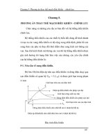
Figure
5
.1
shows
the
ratio,
R
T
/
R
Tr
,
as a function
of
temperature with
the
coefficient,
a
T
,
as
parameter
at
a
reference
temperature
taken
as
T,
.
=
293
K
(20
°C)
.
For
comparative
r
purposes,
the
characteristic
of
a
Pt-1000
RTD
is
also
shown
.
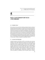
The
voltage-current
characteristic
of
a
thermistor
is
defined
as
the
voltage
drop
across the thermistor
expressed
as
a function
of
the current
flowing
in
it,
with
the
ambient
temperature
of
a
given
surrounding
medium
as a
parameter
.
A
typical
voltage-current
characteristic,
for
a
thermistor
in
still
air
at
the
ambient
temperature,
Oal,
is
shown
in
Figure
5 .2
.
The
characteristics
of
the
same
thermistor
in
still
water
at
the
temperatures
dal
,
6
a2
,
0a3
are
also
shown
in this
figure
.
Initially,
the
thermistor
voltage
drop
is
directly
proportional
to
its
current
.
With
increasing
current,
the
resulting
self-heating
of
the
thermistor
is
accompanied
by
a
commensurate
decrease
of
its
resistance,
so
causing
the
voltage
versus
current
characteristic
to
decrease
.
On
the
V
=J(1)
curves,
for
each
current value, the
corresponding
106
SEMICONDUCTOR
THERMOMETERS
10
I
\
N
~t
5
2
Pt-1004
1
0,5
0,2
OCT,
0,1
\'\\
.
-3,0%K
NTC-THERMISTORS
,~
-3,5%K
0,05
\
.
-3,8%K
-4,0%K
-4,6%
K
-5,0%K
0,02
-5,4%
K
0,01
-20
0
20 40 60 80
100
120 140
160
180
TEMPERATURE
3
,
° C
Figure
5
.1
Resistance,
R
T
,
of a
temperature
sensor
at
temperature,
T
to
R
T
at
293
K
(20 °C) versus
temperature,
temperature
increases,
A61,
1102
.
. .
.
.
.
063,
are also indicated
.
These
values
may
be used
for
the
estimation
of
self-heating errors
.
From
Figure
5
.2
it
can
be seen
that
the
resistance
of
the thermistor
decreases
with
increasing
ambient
temperature,
which
is
also the
measured
temperature,
so
that
its
characteristics
are
shifted
downwards
.
Thermistors
possess
a
heat
dissipation
constant,
C,
given
in
W/K,
similarly
defined
as
the
dissipation constant,
A, for the
RTD
used
in
equation
(4
.10)
.
The
value
of
this
heat
dissipation
constant
depends
on
the
medium
surrounding
the
thermistor
.
For
example,
in
air
C
has
a
value
which
is
smaller
than
its
value
in
water
.
Consequently,
at
the
same
measuring
current,
the
errors
due
to
self-heating
are
larger
in
air
than
in
water
.
In the
same
way
as
for
the
RTD,
C
permits
a
similar
determination
of
the
permissible
measuring
current,
IT,max,
of
a
thermistor
of
resistance,
R
T
,
for
a
given
assumed
self-heating
error,
OO
,
ax
,
as
:
IT,max
D
max
C
(5
.5)
-
T
T
Conversely,
the
self-heating
error,
O6,
at
the
measuring
current,
IT
,
can
be
evaluated
as
:
THERMISTOR
THERMOMETERS
10
7
e~A
Z
A-1,
_0
-TEMPERATURE
RISE
OVER
AMBIENT
e~,
e,93
n4`
e4
;
<
AA,
<
e~3
z
IN
STILL
o
,g
b3
WATER
IN
STILL
AIR
IY
0
CURRENT
I
Figure
5
.2
Voltage-current
characteristics
of
a
thermistor
for
different
ambient
temperatures
,
6a,
and
media
2
AO=
I
C
T
(5.6)
The
permissible
measuring
current,
IT,niax,
must
always be
calculated
at
the
minimum
possible
value
of
R
T
in
the
intended
measuring
range
.
This
value
occurs
at
the
upper
temperature
of
the
measuring
range
.
Numericalexample
Calculate
the
permissible
measuring
current
of
a
thermistor
intended
to
measure
air
temperature
in
a
range
from
0
to
100
°C
.
The
self-heating
error
should
be
kept
below 0
.5
°C
.
In
air
the
heat
dissipation
constant,
C,
has
a
value
of
0
.8x10
-3
W/K,
while
the
thermistor
resistance
at
20 °C
is
R
T
=
8
.5
W
.
Also,
at
this
temperature
of 20 °C (293
K)
the
resistance
temperature
coefficient,
r
aTr
,
has
a
value
of
-4
%/K
or-0
.04
1/K
.
Solution
:
From
equation
(5
.4)
at
a
temperature
T=
373
K
or
100
°C
:
RT
=
RT
e
[a
Tr
AT(T
r
IT)]
=
8
.
5
X
1032[-0
.04x80x293/3733]
=
688
52
r
Inserting
this
value
of
R
T
into
equation
(5
.5)
yields
the
maximum
measuring
current
as
:
3
_
OS
X
0
.8
X
10
-
IT,max
688
0
.76
X
10
-3
A
-
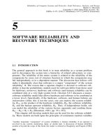
Only
the
initial,
linear
part
of
the
voltage-current
characteristic
shown
in
Figure
5
.3 is
used
for
temperature
measurement
.
The
static
value
of
the
resistance,
R
T
,
of
a
thermistor
at
the
given
temperature,
Dal
,
can
be
calculated,
from
the
values
of
current
and
voltage
in
108
SEMICONDUCTOR
THERMOMETERS
IS
a
U,
w
J
O
-3
.>3
a
>
.~~
0
I,
CURRENT
I
Figure
5 .3 Initial
linear
part
of
voltage-current
characteristics
of a
thermistor,
used
in
temperature
measurement
Figure
5
.3,
as
:
RTI
=V
I
/I
l
(5
.7)
A
comparison
of
the
advantages
and
disadvantages
of
NTC
Termistors
and
of
metallic
resistance
detectors
provides
a
rational
basis
for
the
choice
between
using
a
thermistor
and
a
resistance
detector
.
Compared
with
metallic
resistance
detectors,
NTC
thermistors
have
the
advantages
:
"
smaller
detector
dimensions,
"
higher
temperature
sensitivity,
"
higher
detector
resistance,
which
means
that
readings
are
less
affected
by
the
resistance
of
the
connecting
leads,
"
lower
thermal
inertia
of
the
sensor,
"
possibility
of
measuring
smaller
temperature
differences,
The
main
disadvantages
of
NTC
thermistors
are
:
"
non-linear
resistance
versus
temperature
characteristic,
"
non-standardised
characteristics,
"
lower
measuring
temperature
range,
"
susceptibility
to
permanent
decalibration
at
higher
temperatures
.
Thermistors
of
the
PTC
type,
which
may
be
used
as
binary
temperature
sensors
are
also
produced
in
thin
film
technology
(Morris
and
Filshie,
1982
;
Nagai
et
al
.,
1982)
.
They
are
used
to
protect
semiconductor
devices
and
electrical
machinery
.
At
preset
temperatures
,
such
as
for
example,
35, 55,
75,
95
°C,
the
resistance
of
these
PTC
thermistors
may
increase
from
about
100
0
to
about
100
kf2
with
increasing
temperature
.
THERMISTOR
THERMOMETERS
109
5
.2 .2
Thermistor
sensors
The
most
popular
thermistor
designs,
which
have been
used
for
over
forty
years,
are
in
the
shape
of
beads
and
disks
.
More
recently chip thermistors
have
been
used
.
Different
shapes
of
thermistors,
whose
typical
properties are
listed in
Table
5
.1,
are
represented
in
Figure
5
.4
.
Although
thermistors
are
normally
applied
in
the
temperature
range
from
-100
to
+300
°C,
some
types
for
application
at
high temperatures
and
at
low
temperatures
are
also available
.
The
high
temperature
types
may
be used
at
temperatures
up
to
1200
°C
while
the
low
temperature
components
find
application
in
the
range
from
5
to
200
°C
.
Tolerances
of
the
value
of
R
Tr
for a
given
type
of
thermistor
are
usually
around
5
%
to
20%,
whereas
tolerance for
the
constant,
B,
is
around
5
%
.
These
large
tolerances
are
regarded
as
the
main
disadvantage
in
thermistor
applications
.
Selected
thermistors,
divided
into
various
groups of
narrow
tolerances,
are
available
.
This
ensures
total
interchangeability,
with
temperature
errors
kept
below
±0
.1
to
±0
.2
°C
(Omega
Engineering
Inc,
USA,
1999
;
Cole-Parmer
Instr
.
Co
.,
1999)
.
Their
prices,
are
of
course,
much
higher
.
Beads
are
made
by
allowing
evenly
spacedminute
droppings
of
oxide
slurry
to
fall
upon
two
parallel
stringed
platinum
alloy
wires
.
Owing
to
the
high
surface tension
of
the
slurry,
the
drops
maintain
their ellipsoidal
shape
.
After
drying,
the
drops
are
sintered
at
temperatures
between
1100
°C
and
1400 °C
.
During
the
sintering
process
they
shrink,
so
adhering
to
the
wires
with
a
well
formed
good
electrical
contact
.
Subsequently,
they
are
cut,
as
shown
in
Figure
5
.4(a),
before
being
hermetically
sealed
with
a
glass
or
teflon
layer
which
protects
them
from
oxidation
and
environmental
influences
.
The
wires
have
a
diameter
of
about
0
.0125
to
0
.125
mm
while
the
beads
vary
in
diameter
from
about
0
.1
to
2
mm
(Sapoff,
1972
;
Weichert
et al
.,
1976)
.
Disk
thermistors
are
produced
by
pressing
oxide
powders
under
several tons
of
pressure
in a
round
die
.
After
sintering
they
are
covered
by
a
silver
layer
to
permit
soldering
of
the
terminal
wire
.
The
thermistors,
shown
in
Figure
5
.4(e),
which
are
wholly
protected
by
an
epoxy
layer,
have
diameters
from
1
to 10
mm
and
thicknesses
ranging
from
0
.1
to
2
mm
.
Square
plate thermistors,
also
called
chip
thermistors,
have
dimensions
of
0
.54
.5
mm
to
3x3
mm
and
thicknesses
of
0.025
to
0
.05
mm
.
Stable
glass-covered
disk
thermistors,
whose
indications
do
not
change
more
than
±0
.005
°C
per
year
in
the
temperature
range
from
-
80
°C
to
200
°C, are also
produced
(Wise,
1992
;
Siwek
et al
.,
1992)
.
Portable
thermistor
sensors,
in
the
form
of
probes,
with
extendible
coiled
cables,
are
produced
for
all
types
of
likely
applications
such
as in the
temperature
measurement
of
air,
(a)
BEAD
(b)
GLASS
OR
PLASTIC
(c)
ROD
COATED
BEAD
(d)
ROD
(e)
CHIP
(f)
ROD
WITH
GLASS
TIP
J~
_
Figure
5
.4
Typical
thermistors
Table
5
.1
Typical
NTC
thennistor sensors
Resis-
Heat
di
tance
con
Refer-
tempera-
Constant,
ence
ture
B
In
tempera-
Resis-
coeffic-
[equation
still
Type
Dimensions
ture,
tance,
ient,
aT,
(5
"
1)1
air
(Figure
5
.4)
(mm)
T,
.
(K)
RTr
(%/K)
(K)
(m
Bead
d
;
0
.06
to
1
-
293
1
Bead
(glass
coated)
d
;
0
.1
to
1
-
293
40
b2
to
0
.8
40
MS2
Rod
d
;
0
.5
to
5
1
;
5
to
50
293
-2 to
-6
500
to
Disk
d
; I
to
10
t ;
0
.1
to
2
293
40
S2 to
20000
0
.02
Square
plate
(chip)
lxb
;
0
.5x0
.5
t
;
0
.025
293
1
MQ
up
to
3x3
to
0
.05
Rod
(with
glass
tip)
d
;
1
.5
to
3
1
;
10
to
20
293
2
W
to
-1
10
kQ
1,
length
;
t,
thickness
;
d,
diameter
THERMISTOR
THERMOMETERS
111
liquids,
surfaces
of
solids,
meat,
fruit
and
chemicals
.
More
specialised
areas
of
application
are in
biology
and
medicine
.
In
the
medical
field,
thermistor
probes
are
disposed
of
after
only
one
use
to
avoid
the
possibility
of
cross-contamination
.
This
is
not
unreasonable
as
they
are
comparatively
inexpensive
.
Their
90
%
rise
time
is
about
1
to
3
s
.
Stationary
thermistor
sensors
are
used
in
the
temperature
measurement
of
extruders,
storage
tanks
and
containers,
in
chemical
apparatus
and
in
grain
silos
as
3
to
6
sensor
sets
.
Long
time
instability
of
thermistors,
which
is
mainly
attributed
to
their
resistance
values,
is
caused
by
lattice
structure
changes
due
to
oxidation
and
thermal
tensions
or
by
changes
in
the
resistance
of
the
metallized
contact
.
This
last
cause
seems
to
be
the
most
important
.
The
most
stable
types
are
glass-covered
bead
thermistors,
whose
resistance
does
not
change
more
than
0
.05
to
0
.25
%
per
year,
as
compared
with 0
.5
to
3
%
per
year
for
disk
and rod
thermistors
.
These
resistance
changes
are
usually
easily
compensated
for
in
the
measuring
circuits
by
periodic
calibration
checks
.
In
most
cases
thermistors are
used
with
a
protective
sheath
.
Thermistors,
which
are
generally
supplied
with
their
indicating
meters
by
the
same
manufacturer,
have
many
applications
.
Their
large
signal,
high
sensitivity,
small
dimensions
and
the
possibility
of
applying
long
connecting
leads
make
them
especially
appropriate
in
almost
all
applications
within
their
somewhat
limited
temperature
range
between
about
-50
°C
to
about
300°C
.
Thermistors
are frequently
used
in
the
physical
and
biological
fields
such
as
in
the
food
industry
or
in
medicine
as
detailed
by
Sapoff
(1972)
.
Other
important
areas
of
application
are
in
air
and
liquid
temperature
measurement
as well
as in
the
temperature
measurement
of
small
electronic
elements
and
machine
parts
.
5
.2 .3
Correction
and
linearisation
of
thermistor
characteristics
There
are
two
main
methods
of
guaranteeing
the
interchangeability of
thermistor
sensors
.
"
Production
control
methods
allow
the
selection
and
division
of
thermistors
into
groups
with
a small
scattering
of
the
thermistor
characteristics
.
Subsequently
they
may
be
separated
into
components
with
narrow
temperature
tolerances
.
This
may
be
either
over
a
range
of
temperatures
or
at
a
single
temperature
.
Tolerances
may
be,
for
example,
±0
.05
°C,
±0
.1
°C,
±0
.2
°C
and
±1
°C
which
are
marked
on
the
component
by
a
colour
code
(Sierracin/WesternThermistors,
Oceanside,
USA)
.
"
Array
configuration
methods
employ
the
ideas
associated
with
other
resistance
manufacturing
techniques
(Connolly,
1982
;
Costlow,
1983)
.
Thus
it
is
possible
to correct
and
linearise the
thermistor
characteristics
using
a
computer
program
to
calculate
the
resistor
values
based
upon
the
measured
thermistor
characteristics
at
three
given
temperatures
.
Such
a
procedure
is
carried out
during
production
.
The
non-linear
resistance
versus
temperature
characteristic
is
regarded
as
the
main
disadvantage
of
thermistors
.
This
functional
dependence,
as
given
by
equation
(5
.1),
results
in
decreased
thermistor
sensitivity
at
higher
temperatures
.
Linearisation
may
use
analogue
linearising
circuits
or
it
may
be
digital
(McGhee,
1989)
.
The
digital
approach
uses
a
number
of
different
circuits
.
Analogue
linearisation
is
mainly
based
upon
the
most
convenient
and
classical
method
given
by
Beakley
(1951)
and
Hyde
(1971)
similar
to
those
shown
in
Figure
5 .5
.
For
112
SEMICONDUCTOR
THERMOMETERS
LINEAR
VOLTAGE
OUTPUT
LINEAR
RESISTANCE
OUTPUT
Sn)
(b!
z
R
i
R
z
V=const
.'
R
TE
R
TZ
R~
R=R
l
k~
"
b
R
TE
R,
V
=-k,A
.a
-,
-
Figure
5
.5
Linear
output
thermistor
assemblies
.
R
TI
and
R
TZ
are
thermistors
and
R
I
and
R
Z
are
constant
additional
resistors
example,
Omega
Engineering
Inc
.
(USA)
produces
linear
output
thermistor
assemblies,
which
consist
of
two
or
three thermistors
packaged
as a
single
sensor
and
also include
additional film
resistors
.
They
are
produced
either
as linear
voltage
versus
temperature
as
given
in
Figure
5
.5(a),
or
linear resistance
versus
temperature,
as
in
Figure
5
.5(b)
.
White
(1984)
also
provides
a
technique
used
for the
linearisation
of
resistance
thermometers
.
The
linearity
is
extendedover
a
certain
temperature
range
in
which
the
non-linearity
errors
do
not
exceed
from
±0
.03
to
±1
.1
°C
.
An
assembly
may
have
a
sensitivity
as
high
as
30
mV/K,
which
is
many
times
greater
than
that
of
a
thermocouple
.
For
multi-point
temperature
measurement,
one
resistor
set
can
be used
for
many
thermistor
assemblies
.
In
the
circuit,
given
in
Figure
5
.5(a),
both
positive
or
negative
slope
output
voltage
signals
are
possible
.
Player (1986)
describes
an
extension
of
this
technique
to
give a
wide
range
thermistor
thermometer
.
In
every
10°C
sub-range
the
compensating
network
of
the
thermistor
is
changed
.
As
thermistor
characteristics
are
exponentially
deterministic,
a
logarithmic
amplifier
may
be used
for
linearising
purposes
(Patranabis
et
al
.,
1988)
.
Digital
linearisation
methods
fall
into
various
main
groups
.
A
general
method
applying
one-,
two-
and
three-point
digital
methods
to a
number
of
electrical
output temperature
sensors,
including
thermistors,
is
considered
by
Bolk
(1985)
.
The
technique
of
using
an
analogue-to-digital
converter
described
by
Iglesias
and
Iglesias
(1988)
may
be
adapted
to
suit
thermistors
.
A
final
group
of
methods
uses post-conversion
techniques
based
upon
a
ROM
lookup
table/software
routine
(Brignell,
1985)
.
5
.2
.4
Measuring
circuits
The
common
forms
of
thermistor
thermometer
measuring
circuits
are
deflection
type
bridge
circuits,
like that
shown
in
Figure
5 .6
.
The
bridge
energy
source
may
be
a
battery
cell or
a
rectified
supply
voltage
.
To
ensure
that
the
supplying
voltage
remains
constant,
a
standardising
resistor,
R
s
,
is
provided
.
In
the
position
'O'
of
the
switch,
S,
where
R
S
temporarily
replaces the
thermistor,
R
T
,
the
value
of
R
a
is
adjusted
in
such
a
way
that
the
readings
of
the meter,
M,
are
brought
to
a
marked
scale
position
.
This
is
not
necessary
when
a
stabilised
voltage
source
is
used
.
Measuring
temperatures
ranges
of 30
to
50
°C
may
easily
be
achieved
.
The
whole
measuring
range
is
divided
into
several
selectable
sub-
ranges
.
Most
producers
now
supply
thermistor
thermometers
in
deflection
type
bridge
circuits
with
an IC
output
amplifier
guaranteeing
a precision
of
0
.5
to
1
.0
°C
.
More
THERMISTOR
THERMOMETERS
113
generally,
digital
indicating
instruments
are
used
.
An
example
of
a
digital
meter
based
on
a
bridge
circuit
with
an
A/D
transmitter
is
the
Omega
Thermistor
Thermometer
.
This
meter,
of dimensions
178x84x46
mm,
which
contains
a
digital
100-section
linearisation
circuit,
is
intended
for
use
with
a
6800
thermistor
.
The
same
meter,
which
can
also
be
used
for
thermocouples
and
RTDs,
is
fed
from
a
9V
alkaline
battery,
giving
an
operational
life
of 1200
hrs
.
The
temperature
range
is
20
to
120
°C,
depending
on
the
thermistor
type
used,
with
a precision
better
than
±2
O
C
and
indications
updated
every
0
.5
s
.
For
lower
measurement
precision,
the
simple
series
connected
thermistor
thermometers,
shown
in
Figure
5
.7,
are
also
used
.
They
comprise
a
current limiting
resistor,
R
1
,
and
a
microammeter,
M,
graduated
in
temperature
degrees
.
A
standardising
resistor,
R
S
,
and
switch,
S,
are
also
provided
.
The
permissible
measuring
current
of
the
thermistor
shouldnot
exceed
the
value
calculated
using
equation
(5
.5)
.
Sengupta
(1988)
describes
a
pulse generator
whose
frequency
is
related
to
the
resistance
of
the
thermistor
.
The
principle
of
operation
of
the basic
circuit,
shown
in
Figure
5
.8, is
based
upon
temperature
to
frequency
conversion
.
The
frequency
of
the
square
wave
output
signal
is
:
1
(5
.8)
2R'Cln(1
+
2R
2
/
R1)
Since
the
resistance
versus
temperature
characteristic
of
the
thermistor
has
an
exponential
form,
replacing
R
2
by
the
thermistor
resistance
allows
cancellation of the
exponential
VOLTAGE
SETTING
E
R
Q
<R3
Rp
'C
M
J
,0
-11
"
S
R,
.,m
CORRECTING
RESISTOR
THERMISTOR
R,
R
T
R,,R
2
,R
3
-CONSTANT
I
Rs
RATIO
RESISTORS
V
STANDARDIZATION
S
MEASUREMENT
RT
M
f
°C
R~
THERMISTOR
Figure
5
.6
Deflection
type
bridge
circuit
for
Figure
5
.7
Series
connected
thermistor
a
thermistor
thermometer
thermometer
114
SEMICONDUCTOR
THERMOMETERS
la)
R,
(b)
V
o
V=
-
t
+
"
R,
!
-V=
lJ LJ
L
V
o
C
R
Z
Figure
5
.8
Thermistor
thermometer
with
linear
temperature
to
frequency
conversion
behaviour
by
the
logarithmic
term
in
the
expression
.
Although
complete
cancellation
cannot
be
achieved
with
this
simple
circuit,
good
linearity
over
a
limited
temperature
range
is
possible
.
Sengupta
(1988)
shows
how
the
linearity
may
be extendedby
including
additional
switching
transistors
.
The
transistors
switch
different
resistors
into
the
circuit
to
give
different
time
constants
for
charging
and
discharging
of
the capacitor
.
In
this
manner
the
output
voltage
is
saturated
for
longer
at
one
supply
rail
voltage
than
it
is
at
the other
.
5
.3
Silicon
Resistance
Thermometers
Silicon
resistance
thermometer
detectors,
or
Si-RTDs,
also
called
Silistors
by
Hyde
(1971),
are
PTC
silicon
resistors
.
Their
manufacturing
technology
is
based
upon
the
familiar
planar
technology,
which
has
proved
extremely
successful
in
the
manufacture
of
other
semiconductors
.
There
are four
principal
steps
in
their
productions
(Philips
Components
Ltd,
UK)
.
A
neutron
transmutated
doped
(NTD)
silicon
wafer
of
30 Si
is
irradiated
with
neutron
radiation to
produce
3
1
Si
.
This
31
Si
then
decays
to
produce
the
n-type
dopant
31
P
.
Extremely
low
spreads
in
dopant
density,
which
are
required
for
the
tight
tolerance
in
sensor
resistance,
result
from
the use
of
this
process
.
The
growth of
a
glass
layer,
during
the
subsequent
n+
diffusion,
and
silicon
nitride
passivation
ensure long-term
stability
.
Metallisation
prevents
contamination
and
migration
.
Finally,
galvanic
growth of
silver
mushroom
contacts
is
completed
.
This
ensures
good
pressure contact
for the
KTY83/KTY85
series
.
All
of
the
sensors
may
be
supplied
with
different
types
of
encapsulation
.
Doped
Si,
in
the
`normal'
region
of
semiconductor
behaviour,
has
a
resistivity
given
by
:
2
.3
P =
P25
(
298)
(5
.9)
Equation
(5
.9)
gives
a
power
series
expansion
for the
resistance,
which
is
similar
to
that
of
a
Pt-RTD,
in
the
form
:
R
T
=R
Tr
[1+A(T-T
r
)+B(T-T
r
) 2
]
(5
.10)
The
constants,
A
and
B,
depend
upon
sensor
type
as
shown
in
Table
5
.2,
while
R
Tr
is
the
SILICON
RESISTANCE
THERMOMETERS
115
nominal
resistance
of
the
sensor
at
the reference
temperature,
T
r
.
Hence,
it
is
a
simple
matter
to
store
a
calibration
table
in
ROM
for
high
precision
microprocessor-based
applications
.
A
resistance-temperature
coefficient
can
be
defined
for
these
devices
in
the
same
way
as
for the
Pt-RTD
.
Table
5 .2
gives
details
of
a
selection
of
Si-RTDs,
which
may
be
applied
in
simple
or precision
temperature
measurement
or
in
temperature
compensation
.
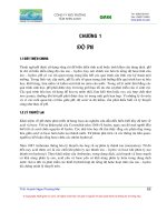
The
resistance
versus
temperature
characteristics
of
Si-RTDs
are
shown
in
Figure
5
.9
.
As
sampled
acceptance
testing
is
made
to
military
standard
MIL
STD
105D,
the
reliability
and
stability
of
Si-RTDs
are
comparatively
good
.
A
significant
contribution
is
made
to
these properties
by
the
planar
manufacturing
process
itself
which
helps
to
ensure
high
quality
and
exceptional
reliability
.
Reliability testing
is
performed
under
maximum
rated
operating
conditions,
as part
of
the
product
acceptance
screening
at
the
production
level
.
Tests
include constant
operation
to
estimate
stability,
temperature
cycling
and
storage
at
high
and
low
temperatures
.
The
typical
value
of
drift,
measured
at
150
°C
after
2000
hours
of
operation,
lies
between
0
.13
and
0
.15
K
with
the
maximum
in
the
range
from
0 .38
to
0
.66
K
.
Estimated
lifetimes
in
the
range
155 000
to
250
000
hours
indicate
the
reliability
of
Si-RTDs
.
Figure
5 .10
shows
a
circuit
diagram
for
a
simple
temperature
measurement
application
using
a
Si-RTD
.
This
circuit
may
be
used
to
measure
the
temperature
of
rooms,
ovens,
electric
irons
and
domestic
and
industrial
water
heaters
.
Resistor
R
1
and
the
parallel
combination
of
R
2
and
the
sensor
form
one
arm
of a
Wheatstone
bridge
.
The
other
arm
is
formed
by
R
3
,
a
potentiometer
P
t
and
R
q
.
The
values
of
R
t
and
R
2
are
chosen
so as to
linearise the
sensor
characteristic
over
the
temperature
range
of
interest
.
Calibration
is
achieved
by
setting
the
potentiometer
P,
until
V
D is
1
V
when
the
sensor
temperature
is
0
°C
.
At
a
higher
temperature,
say
100
°C,
P
2
is
adjusted
until
the
output
voltage,
V
o
,
is
at
the
correct
span
level
.
Notice
that
adjustment
of
P
2
does
not
affect the
zero
of
the
scale
.
Resistance
detectors
produced
in
germanium
using
layer
technology,
are
similar
to
Si-
RTDs
.
Although
they
are
mainly
intended
for
use
at
low
temperatures,
they
can
be used
up
to
about
300
K
.
(Beasley
and
Kemp,
1977
;
Institute
of
Semiconductor
Physics,
Kiev,
1997)
.
4,8
I
4,0
KTY86-205
'
01
3,2
KTY81-2
2,4
',KTY81-
~KTY83-1
N
0,8
0
.
1,6
KTY85-1
-100
-50
0 50
100
150
200
TEMPERATURE
3,
°C
Figure
5
.9
Resistance
vs
temperature
characteristics
of
some
Si-RTDs
(Courtesy
of
Philips
Components
Ltd
.)
116
SEMICONDUCTOR
THERMOMETERS
Table 5
.2
Important
parameters
for
KTY
silicon
temperature
sensors
.
(Reproduced
by
permission
of
Philips
Components
Ltd
.,
UK)
Measuring
Sensor
constants
Operating
Nominal
temperature
(Equation
5
.10)
current
resistance,
range
A
B
I
Series
RT
r
(S2)
T
r
(K)
(°C)
(%
/
K)
(%
/K
Z
x10
3
)
(mA)
KTY81-1
980
to
1050
298
-55
to
150
0
.7874
1
.874
1
(7
types)
KTY81-2
1600
to
2100
298
-55
to
150
0
.7874
1
.874
1
(7
types)
KTY83-1
950
to
1050
298
-55
to
175
0
.7635
1
.731
1
(7
types)
KTY84-1
950
to
1050
373
0
to
300
0
.6116
1
.025
2
(4
types)
KTY85-1
950
to
1050
298
-40
to
125
0
.7635
1
.731
1
(7
types)
KTY86-2
1990
to
2010
298
-40
to
150
0
.7646
1
.752
1
(1
type)
*
V
b
R
t
R
s
Re
-i"
P1 R
5
_
P2
er
r
R
R
~~
+
112
N
E 532
W
v
t-
I
t
2 4
1
0
YL_
~
Si
-RTo
TEMPERATURE
SENSOR
Figure
5
.10
Simple
temperature
measuring
circuit
using
a
KTY81
sensor
.
(Courtesy
of
Philips
Components
Ltd
.,
UK)
5
.4
Diode
and
Transistor
Thermometers
5
.4
.1
Principles of
operation
Diodes
and
transistors
are
junction
semiconductor
devices
whose
current
versus
voltage
characteristics
are substantially
determined by
the
relations
between
carriers
on
each
side
of
a
semiconductor
junction
.
The
carrier
density
is
strongly
temperature
dependent
.
Consequently,
as
quoted
by
Sze
(1969)
and
van
der
Ziel
(1968)
and
taking
account
of
the
more
accurate
notation
of
Tsividis
(1980),
the
current,
I
d
(T),
flowing through
the
junction
DIODE
AND
TRANSISTOR
THERMOMETERS
117
of
a
semiconductor
diode
may
be
written as
:
Id
(T)
=
Iso(T)egVd
IkT
(5
.11)
with
the
reverse
saturation
current,
Iso(T),
given
by
:
T1
_
gAT'D(]r)e
gVI(T)1kT
I
so(`
l
-
(5
.12)
N
B
where
A
is
the
base-emitter
area
of
the
diode
junction,
k
is
the
Boltzmann
constant,
q
is
the
electron charge,
T
is
the
absolute
temperature
in
K,
V
g
(T)
is
the
temperature
dependent
energy
gap
for
a
given
material,
N
B
is
the
Gummel
number
(total
number
of
impurities
per
unit
area
in
the
base of
the
diode),
D(T)
is
the
temperature
dependent
effective
minority
carrier
diffusion
constant
in
the
base,
and
V
d
is
the
forward
voltage
across
the
device
.
As
diodes
may
be
operated
in
either
reverse
bias
or
forward
bias
modes
it
is
possible
to
measure
temperature
by
measuring
either
reverse
saturation
current or
forward
voltage
.
Take
logarithms
on
each
side
of
equation
(5
.12),
then
differentiate explicitly
to
obtain the
temperature
coefficient
of
the
reverse
saturation
current
as
:
so
_=
C3
+
D
+
q
Vg(T)
kT
dV
dT
]
T
(5
.13)
so
It is
easy
to
calculate
that
the
temperature
coefficient
of
equation
(5
.13)
doubles
for
every
10
°C
rise in
temperature
.
Under
conditions
of
temperature
independent
constant
forward
current the reverse
saturation
current
can
be
neglected
.
The
temperature
coefficient,
dV
d /
dT,
of
V
d
may
be
found
as
follows
.
Differentiate
equation
(5
.11)
with
respect to
temperature
to
find
:
di
d
d
T
-
[
dIT
+
Iso(-
kT2
Vd
+
kT
dT
)]e
qV
d
1
kT
(5
.14)
Since
the
forward
current
is
independent
of
temperature,
equation
(5
.14)
can
be
solved
for
i3Vd
/ a T
to obtain
:
dVd-
k(dlso/Iso)
_
gVd
_-
-2
mV/K
for Si
at
T=
300
K
(5
.15)
dT
q(dTIT)
kT
2
-1
.25mV/K
forGc
The
effects
of
temperature
in
transistors,
which
are
similar
to
those in diodes,
are
detailed
by
Sah
(1961)
.
His
expression
for
the
short-circuit
collector
current,
ICs,
in
many
kinds
of
transistor
has
been
given
more
detailed
attention
by
Tsividis
(1980)
who
wrote
the
equation
in
the
form
:
IC
(T)
=Is(T)egVbeI
kT
(5
.16)
118
SEMICONDUCTOR
THERMOMETERS
where
IC
(T)
is
the
collector
current,
I
s
(T)
is
the
temperature
dependent
reverse
saturation
current
of
the
base-emitter
junction
and
V
be
is
the
base-emitter
voltage
.
Equation
(5
.16),
which
is
valid
for
both
diffusion
and
drift
devices,
has
a
similar
notation
as in
equation
(5
.11)
.
5
.4
.2
Diode
thermometers
The
temperature
measuring
range
of
diode
thermometers
is
limited
by
maximum
permissible
junctiontemperature
and
by
the
range
of
linearity
of
the
output
signal
.
Typical
measuring
range
of
Si
diodes
is
-50
to
+150
°C
.
Talpe
et al
.,
(1987)
describe
the
use
of
common
diodes
in
even
cryogenic
thermometry
but
linearisation
of
their
characteristic
is
then
necessary
.
Diode
thermometers,
fabricated
from
the
compound
semiconductor
GaAs,
may
be used
in
the
temperature
range
from
2
to
300
K
(Cohen
et
al
.,
1963)
.
However,
they
are
about
fifty
times
less
sensitive
than
Si
diodes,
which
are
consequently
more
popular
.
The
forward
voltages,
V,
of
Ge,
Si
and
GaAs
diodes, as a
function
of
temperature,
T,
are
given
in
Figure
5
.11
(Rao
et
al
.,
1983)
.
In
practice
the nearly
linear
range
of
the
V=
f(T)
characteristic
is
used,
where
the
non-linearity
errors
of
about
±1
to
±3%
of
full
scale
deflection
.
A
typical
measuring
circuit
is
shown
in
Figure
5
.12
.
For
correct
operation
of
the
thermometer
it
is
necessary
to
control the
biasing
level
of
the
diode
current
.
If
the current
is
too
low,
the
V
=
f(T)
dependence
becomes
non-linear
due
to
the
influence
of
the reverse
saturation
current
.
When
the current
is
too
large,
the
heat
generated
in
the
diode
junction
causes
a
self-heating error
due
to
the increase
in
electron-
hole
pair
generation
in
the
junction
depletion
.
In
simple
measuring
circuits,
the non-linear
errors
are
about
±1
to
±3%
of
full
scale
deflection
.
Weichert
et
al
.,
(1976)
have
stated
that
2,0
158
w
GaAs
1,16
1,0
0
0,75
Ge
0,5
0
0
100
200
300 400
TEMPERATURE
T
,
K
Figure
5
.11
Forward
voltage
versus temperature
of
some
semiconductor
diodes
(Rao
et
al
.,
1983)
DIODE
AND
TRANSISTOR
THERMOMETERS
119
CURRENT
STABILIZING
RESISTOR
R
T
°C
V
V~
0
Figure
5
.12
Circuit
for
a
diode
thermometer
high
input
impedance
analogue
voltmeters
should
be
used
for
temperature
readings
.
Presently
high
input
impedance
digital
voltmeters
combined
with
other
special
circuits
(Griffiths
et
al
.,
1974)
are
more
widely
used,
especially for
accurate
temperature
measurement
in
the
range
-50
to
+30
°C
.
The
repeatability
of
the
readings
of
diode
thermometer
is
usually
below
±50
mK
.
The
overall
measuring
errors
may
be
as
much
as
f4
oC
unless
adequate
precautions
to
ensure
proper
screening
and
earthing
are
taken
.
5
.4 .3
Transistor
thermometers
Transistor
thermometers,
which
have
a
similar
temperature
measuring
range
as
that
of
diode
thermometers,
results
from
the
permissible
collector
and
base
junction
temperatures
and
the
linear
range
of the
thermometric
characteristic
.
Usually
this
range
covers
-50
to
+150OC
.
The
basic
operating
principle
of
transistor
thermometers,
normally
fabricated in
Si,
is
given
by
Felimban
and
Sandiford
(1974),
and
expressed
in
equation
(5
.16)
.
They
are
much
more
sensitive
than
diode
thermometers
because
of
the
current
amplification
factor
.
Although
transistors
can
be used
as
thermometers
by
measuring
either
short
circuit
collector
current
or
base-emitter
voltage,
the
base-emitter
connection
is
more
commonly
used
because
of
the
simple
way
of
connecting
the
transistor
into
the
feedback
path
of
an
operational
amplifier
.
The
base-emitter
voltage,
Vbe,
as
a function
of
temperature,
T,
of
a
transistor
is
given
by
the
equation(Ruehle,
1975)
:
V
be
=
AT
In
C
I
e
+
Ie
(5
.17)
Ieo
where
A
is
a constructional
constant,
I
e
is
the emitter
current
and
I
eo
is
the emitter reverse
saturation
current
.
Figure
5
.13
shows
a frequently
used
measuring
circuit
described
by
Verster
(1968,
1972)
and
Swartz
and
Gaines
(1972)
.
The IC
operational
amplifier,
A
l ,
should
be
characterised
by
small
variations
in
input
offset
current,
whilst
A
2
should
have
small
variations
in
input
offset
voltage
.
The
resistor,
R
1
,
is
used
for
setting
the
transistor
collector
current,
with
the
setting
of
resistor,
R
2
,
fixing
the
reference
temperature
.
Matching
of
the
120
SEMICONDUCTOR
THERMOMETERS
circuit
gain
to
the
indicating
meter,
in
most
cases
a
digital
voltmeter,
is
allowed
by
the
resistor,
R
4
.
Every
time
the
sensor
is
changed,
the
resistor,
R
1 ,
has
to
be
reset
.
The
base-
emitter
voltage,
Vbe,
is
a
nearly
linear
function
of
temperature
.
A
similar
circuit
described
by
Ruehle
(1975)
uses
the
transistor
as
part
of
a
bridge
.
An
additional operational
amplifier
simultaneously
ensures
that
the
base
and
collector
currents
are
held
constant
.
The
base-
emitter voltage,
V
be
,
is
then
a
linear
function
of
temperature
in
the
range
from
1
to
5
V,
having
non-linearity
errors
smaller
than
0
.05%
.
As
all
diode
and
transistor
sensors exhibit a
non-linear
temperature
dependence,
their
signals
require
linearisation
(Davies
and
Coates,
1977)
.
Verster
(1968,
1972)
uses
a
technique
of
linearisation
based
upon
a
circuit
which
switches
the
short
circuit
collector
current
of
a
2N1893
device
between
57
.3
pA
and
5
.0
1tA
.
Over
the
range
-100
°C
to
+100
°C
the
temperature
may
be
resolved
to
within
±0
.01
°C
.
Ohte
and
Yamagata
(1977)
describe
how
the application
of
feedback
compensation
can
linearise the
voltage
versus
temperature
characteristic
.
The
overall
deviation
from
linearity
is
within
±0
.1
°C
over
the
temperature
range
-50
to
+125
°C,
with
long-term
drift
of
some±0
.2
°C
in
a
24
000
hour
test
.
The
thermometer
time
constants
in
stirred
water
were
0
.2
s
for
a
minisensor
and
0
.9 s
when
used
with
a
needle
sheath
compared
to
7
s
with
a
stick
probe
.
An
application
for
temperature
measurement
in a
meteorological
sounding
balloon,
using
the
2N2222
n-p-n
Si
transistor,
has
been
reported
by
Sridaran
et
al
.,
(1987)
.
The
circuit,
operating
at
a
constant
emitter-base
voltage
of
0
.6
V,
is
based
upon
the
temperature
dependence
of
the
collector
current,
which
increases
from 10
-1
I
to
10-
4
A
for
temperature
variations
from
170
to
310
K
.
An
error
limit
of±1 °C
is
reached
.
Feedback
is
also
used
to
improve
the
linearity
and
stability
of
this
thermometer
.
Transistor
pairs,
packaged
in
a
single
sheath,
are
also
used
.
Verster
(1972)
has
reported
a
special
electronic
circuit
which
maintains
both
stabilised
and
constant
collector
currents
.
Their
output
voltage,
which
is
a
linear
temperature
function,
can
be
easily
adapted
to
a
new
sensor
by exchanging
one
resistor
in
the
measuring
circuit
.
If
the
circuit
is
designed
as
an
integrated
unit
then
self-heating
errors
may
be
a
problem
.
A
digital
voltmeter
is
the
typical
instrument
for
indicating
the
temperature
values
acquired
by
the
circuit
which
has
a
sensitivity
of
10
mV/K
.
Rt
R2
_
A,
R
4
R3
A2
q-
T
I
I
vbe
V
o
Figure
5
.13
Transistor,
T, as
a
temperature
sensor
INTEGRATED
CIRCUIT
THERMOMETERS
121
5
.5
Integrated
Circuit
Thermometers
When
two
transistors
are
operated
at
a
constant
ratio
of
unequal
emitter
currents
the
difference
between
their
base-emitter
voltages
is
proportional
to
absolute
temperature
often
abbreviated
to
PTAT
.
Integrated
circuit,
IC, or
monolithic
temperature
sensors,
which
are
designed
on
the
basis
of
this
effect,
provide
either
an
output
current
or
voltage
referred
to
as
IPTAT
and
VPTAT
respectively
.
They
were
developed
following
the
seminal
work
of
Hilbiber
(1964)
and
Widlar(1965)
.
Taking
equation
(5
.16) into
account
in
considering
the
circuit
of
Figure
5
.14
follows
the
approachof
Timko
(1976)
.
It
can
be shown
that
the
voltage
VT,
across
the
resistor,
R,
in
terms
of
the emitter current
ratio,
r,
as the
base-emitter
voltage
difference
of
T
2
and
T
4
,
is
:
V
T
=T
kIn r
(5
.18)
9
If this
voltage
were
buffered
and
amplified
it
would
provide
a
signal
directly
proportional
to
absolute
temperature
.
This
is
the
basis
of
operation
of
integrated
circuit
VPTAT
temperature
sensors
as
well
as
band-gap
references
.
Current
mirror-based
VPTAT
circuits,
like that
shown
in
Figure
5
.14,
are
the
foundation
of
a
numberof
developments
in
IC
temperature
sensors
(de
Haan
and
Meijer,
1980
;
Meijer,
1980
;
Regan,
1984
;
R
.
S
.
Components
Ltd,
1987
;
Meijer
et
al
.,
1989
;
National
Semiconductors
Corp
.,
1989)
.
On
the
other
hand,
the
current,
I,
drawn
from
each
side
of
the
circuit,
which
is
equal
to that
flowing
in
the
resistor,
R
is
equal
to
:
1=
T
In
r
(5 .19)
9
Under
the
same
assumptions
as
for the
VPTAT
output
it
is
apparent
that
a
IPTAT
output
is
also
possible
.
This
is
the
basis
of
operation
of
the
sensor
developed
by
Timko
(1976)
and
now
available
from
Analog
Devices
Inc
.
(1989)
and
second
sourced
by
R
.
S
.
Components
Ltd (1983)
.Omega
Engineering
Inc
(1999)
offers
semi-conductor
sensors
based
on
the
AD590
IC, exhibiting
linear
current or
voltage
output
signals
.
These
sensors
can
be
applied
T1
T2
T3
T4
V
T
PR
Figure
5
.14
Basic
PTAT
circuit
122
SEMICONDUCTOR
THERMOMETERS
in
the
temperature
range from
-50
to
+150
°C,
especially
when
high
precision
and
accuracy
are
required
.
In
versions
with
current
output the
sensitivity
is
about
1
NA/°C
.
With
voltage
output
an
intrinsic
sensitivity
of
I
mV/°C
can
be
increased
to
100
mV/°C
using
an
additional
IC
amplifier
.
5
.6
References
Aleksic,
Z
.J
.
and
Vasiljevic,
D
.M
.
(1986)
Low-power
temperature
detector
and
rate
of
temperature
change
detector
.
IEEE
Trans
Instr
.
Meas
.,
IM-35(4),
571-575
.
Arora,
N
.D
.,
Hauser,
J
.R
.
and
Roulston,
D
.A
.
(1982)
Electron
and
hole
mobilities
in
as
a
function
of
concentration
and
temperature
.
IEEE
Trans
Elec
.
Dev
.,
ED-29(2),
292-295
.
Beakley,
W
.R
.
(1951)
The
design
of
thermistor
thermometers
with
linear
calibration
.
J
.
Sci
Instrum
.,
28(6),
176-179
Beasley,
L
.M
.
and
Kemp,
W
.R
.G
.
(1977)
An
intercomparison
of
temperature
scales
in
the
range
1-30
K
using
germanium
resistance
thermometry
.
Metrologia
13,
35-51
.
Becker,
J
.
A
.,
Green,
C
.
B
.
and
Pearson,
G
.
L
.
(1946)
Properties
and
uses
of
thermistors
-
thermally
sensitive
resistors
.
Trans
.
AIEE,
65,
711
.
Bolk,
W
.T
.
(1985)
A
general
linearising
method
for
transducers
.
JPhys
.
E
:
Sci
.
Instrum
.,
18,
61-64
.
Bosson,
G
.,
Gutmann,
F
.
and
Simmons,
L
.M
.
(1950)
A
relationship
between
resistance
and
temperature
of
thermistors
.
J
.
App
.
Phys
.
21,
1267-1268
.
Brignell,
J
.E
.
(1985)
Interfacing
solid
state
sensors
with
digital
systems
.
J
.
Phys
.
E
:
Sci
.
Instrum
.,
18,
559-565
.
Cohen,
B
.G,
Snow,
W
.B
.
and
Tretola,
A
.R
.
(1963)
GaAs
p-n
junction
diodes
for
wide
range
thermometry
.
Rev
.
Sci
.
Instrum
.,
34(10),
1091-1093
.
Cole-Parmer
Instr
.
Co
.
(1998)
Thermistors-Temperature
.
General
Catalogue
199912000,
1081-1086
.
Connolly,
E
.
(1982)
Focus
on
resistor
networks
:
they save
space,
connections
.
Electronic
Design,
March
31,
125-136
.
Costlow,
T
.
(1983)
Precision
resistors
track
networks
path
to
better
performance
.
Electronic
Design,
Feb
.
17,
99-102
.
Davies,
C
.E
.
and
Coates,
P
.B
.
(1977)
Linearisation
of
silicon
junction
characteristics for
temperature
measurement
.
J
.
Phys
.
E
.
Sci
.
Instrum
.,
10(6),
613-616
.
de
Haan,
G
.
and
Meijer,
G
.C
.M
.
(1980)
An
accurate
small-range
IC
temperature
transducer
.
IEEE
J
.
Sol
.
St
.
Circ
.,
SC-19(5),
1089-1091
.
Droms,
C
.R
.
(1962)
Thermistors
for
temperature
measurement
.
Temperature
:
Its
Measurement
and
Control
in
Science
and
Industry,
3(2),
Reinhold
Publ
.
Co
.,
New
York
.
339-346
.
Felimban,
A
.A
.
and
Sandiford,
D
.J
.
(1974)
Transistors
as
absolute
thermometers
.
J
.
Phys
.
E
.
:
Sci
.
Instrum
.,
7,
341-342
.
Griffiths,
B
.,
Stow,
C
.D
.
and Syms,
P
.H
.
(1974)
An
accurate
diode
thermometer
for
use
in
thermal
gradient
chambers
.
J
.
Phys
.
E
.
:
Sci
.
Instrum
.,
7,
710-714
.
Hilbiber,
D
.F
.
(1964)
A
new
semiconductor
voltage standard
.
ISSCC
Dig
.
Tech
.
Papers,
32-33
.
Hyde,
F
.
J
.
(1971) Thermistors
.
Iliffe
Books,
London
.
Iglesias,
E
.
G
.
and
Iglesias,
E
.
A
.
(1988)
Linearisation
of
transducer
signals
using
an analog-to-digital
converter
.
IEEE
.
Trans
.
Instr
.
Meas
.,
IM-37(1), 53-57
.
Institute
of
Semiconductor
Physics,
Kiev
(1997),
Ukraine,
Ge
Film
Resistance
Thermometers,
TTR-
1
A
.
REFERENCES
123
McGhee,
J
.
(1989)
The
impact of
electronics
and
information
technology
upon
measurement
and
control
in
thermal
systems
.
Keynote
lecture
IMEKO
TC-12
Symp
.
Microprocessors
in
Thermal
and
Temperature Measurements,
Lodz,
Poland
Meijer,
G
.C
.M
.
(1980)
An
IC
temperature
transducer
with an
intrinsic
reference
IEEE
.
J
.
Sol
.
St
.
Cir
.,
SC-15(3),
370-373
.
Meijer,
G
.
C
.
M
.,
van
Gelder,
R
.,
Nooder,
V
.,
van
Drecht,
J
.
and
Kerkvliet,
H
.
(1989)
A
three
terminal
integrated
circuit
temperature
transducer
with
microcomputer
interfacing
.
Sensors
and
Actuators,
18,
195-206
.
Morris,
W
.M
.
and
Filshie,
J
.H
.
(1982)
Thin
film
thermistor
.
J
.
Phys
.
E
:
Sci
.
Instrum
.,
15(5),
411-414
.
Nagai,
T
.,
Yamamoto,
K
.
and
Kobayashi,
I
.
(1982)
SiC-thin
film
thermistor
.
J
.
Phys
E
.
Sci
Instrum
.,
15(5),
520-524
.
National
Semiconductor Corp
.
(1989)
Data
Sheets
for
LM34
and
LM35
Series
of
temperature
sensors
.
Ohte,
A
.
and
Yamagata,
M
.
(1977)
A
precision
silicon
temperature
thermometer
.
IEEE
Trans
Instr
.
Meas
.,
IM-26(4),335-341
.
Omega
Engineering
Inc
.
(1999)
The
Temperature
Handbook
Patranabis,
D
.,
Ghosh,
S
.
and
Bakshi,
C
.
(1988)
Linearising
transducer
characteristics
.
IEEE
Trans
.
Instr
.
Meas
.,
IM-37(1),
66-69
.
Pavese,
F
.
(1974)
An
accurate
equation
for the
V-T
characteristic
of
a
GaAs
diode
thermometer
in
the
4-300K
range
.
Cryogenics,
14(8),
425-428
.
Player,
M
.A
.
(1986)
A
simple
wide-range
thermistor
thermometer
.
J
.
Phys
.
E
:
Sci
.
Instrum
.,
19,
787-
789
.
Rao,
M
.G
.,
Scurlock,
R
.G
.
and
Wu,
Y
.Y
.
(1983)
Miniature
silicon
diode
thermometers
for
cryogenics
.
Cryogenics,
23(12),
635-638
.
Regan,
T
.
(1984)
Applying
the
LM35
temperature
sensor
.
Electronic
Prod
Des
.,
November
85
-86
.
Roess,
E
.
(1984)
Properties
and
uses
of
thermistors
.
Electronic
Prod
Des
.,
June,
179-185
.
R
.S
.
Components
Ltd,
London
(July
1983)
Data
Sheet
3992
for
Semiconductor
temperature sensor
stock
number
308-809
.
R
.S
.
Components
Ltd,
London
(Nov
.
1987)
Data
Sheet
8307
for
LM35Z
and
LM35DZ
Temperature
sensor
IC
.
Ruehle,
R
.A
.
(1975)
Solid
state
temperature sensor
outperforms
previous
transducers
.
Electronics,
48(6),
127-130
.
Sah,
C
.T
.
(1961)
A
new
semiconductor
tetrode-the
surface-potential
controlled
transistor
Proc
.
Inst
.
Radio
Engrs,
49,
1623-1634
.
Sachse,
H
.B
.
(1975)
Semiconducting
Temperature
Sensors
and
Their Applications,
John
Wiley
and
Sons,
New
York
.
Sapoff,
M
.
(1972)
Thermistors
for
biomedical
use
.
Temperature
:
Its
Measurement
and
Control
in
Science
and
Industry,
4(3),
Instrument
Society
of
America,
Pittsburgh
2109-2124
.
Sengupta,
R
.N
.
(1988)
A
widely
linear
temperature
to
frequency
converter
using
a
thermistor
in
a
pulse
generator
.
IEEE
Trans
.
Instr
.
Meas
.,
IM-37(1), 62-65
.
Siwek,
W
.R
.,
Sapoff,
M
.,
Goldberg,
A
.,
Johnson,
H
.
C
.,
Botting,
M
.,
Landsdorf,
R
.
and Weber,
S
.
(1992)
Thermistors
for
biomedical
thermometry
applications
.
Temperature
:
Its
Measurement
and
Control
in
Science
and
Industry,
6(2),
American
Institute
of
Physics,
New
York,
475-480
.
Sridaran,
S
.,
Das,
S
.R
.
and
Raghavarao,
R
.
(1987)
A
novel
temperature
probe
for
middle
atmospheric
and
meteorological
applications
J
.
Phys
.
E
:
Sci
.
Instrum
.,
20(10),
1198-
1201
.
Stanley,
K
.
W
.
(1973)
Non-linear
resistors
.
Radio
and
Electronic
Eng
.,
43(10),
1-4
.
Swartz,
J
.M
.
and
Gaines,
J
.R
.
(1972)
Wide
range
thermometry
using
gallium
.
Temperature
:
Its
124
SEMICONDUCTOR
THERMOMETERS
Measurement
and
Control
in
Science
and
Industry,
4(2),
Instrument
Society
of
America,
Pittsburgh,
1117-1124
.
Sze,
S
.M
.
(1969)
Physics
of
Semiconductor
Devices,
John
Wiley and
Sons,
New
York
.
Talpe,
J
.,
Stolovitzky,
G
.
and
Bekeris,
V
.
(1987)
Cryogenic
thermometry
and
level
detection
with
common
diodes
.
Cryogenics,
27,
693-695
.
Timko,
M
.P
.
(1976)
A
two-terminal
IC
temperature
transducer
.
IEEE
J
.
Sol
.
St
.
Circ
.,
SC-11(6),
784-
788
.
Tsividis,
Y
.
(1980) Accurate
analysis
of
temperature
effects
in
I
C-V
BE
characteristics
with
application
to
bandgap
reference
sources
.
IEEE
J
.
Sol
.
St
.
Cir
.,
SC-15(6),
1076-1084
.
Verster,
T
.C
.
(1968)
p-n
junction
as
an
ultralinear
calculable
capacitor
.
Electronics
Letters,
4(9),
175-
176
.
Verster,
T
.C
.
(1972)
The
silicon
transistor
as
a
temperature
sensor
.
Temperature
:
Its
Measurement
and
Control
in
Science
and
Industry,
4(2),
Instrument
Society
of America,
Pittsburgh,
1125-1134
.
Weichert,
L
.
(Editor)
.
(1976)
Temperaturmessung
in
der
Technik-Grundlagen
and
Praxis
.
Lexika-
Verlag,
Grafenau
.
Widlar,
R
.J
.
(1965)
Some
circuit
design
techniques
for
linear
integrated
circuits
.
IEEE
Trans
.
Circ
.
Theory,
CT-12,586-590
.
White,
D
.R
.
(1984)
The
linearisation
of
resistance
thermometers
.
J
Phys
.
E
:
Sci
.
Instrum
.,
17,
381-
385
.
Wise,
J
.A
.
(1992)
Stability
of
glass-encapsulated,
disc
type
thennistors
.
Temperature
:
Its
Measurement
and
Control
in
Science
and
Industry,
6(1),
American
Institute
of
Physics,
N
.Y
.
481-
484
.
Ziel,
A
.
van
der
(1968)
Solid State
Physical
Electronics
.
Prentice-Hall,
Englewood
Cliffs
.
NJ