Hệ thống truyền thông di động WCDMA P2 pot
Bạn đang xem bản rút gọn của tài liệu. Xem và tải ngay bản đầy đủ của tài liệu tại đây (913.01 KB, 60 trang )
2
Radio Transmission Systems
Mamoru Sawahashi
2.1 Direct Sequence Code Division Multiple Access (DS-CDMA)
2.1.1 Principles of DS-CDMA
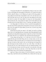
DS-CDMA is a radio-access technology that enables multiple access based on a spread
spectrum system. Figure 2.1a shows how DS-CDMA works [1–3]. The transmitted data
sequence is spread across the spectrum after being encoded by spreading codes, each
of which is assigned uniquely to each user at a higher rate than the symbol rate of the
information data. [Wideband Code Division Multiple Access (W-CDMA) spreads the
information data over a 5 MHz band per carrier.] The spread high-speed data sequence is
referred to as chip and the rate at which the spread data varies is called chip rate. The ratio
of chip rate to symbol rate is called the Spreading Factor (SF). The destination mobile
phone uses the same spreading code as the one used for spreading at the transmission
point to perform correlation detection (a process called despreading), in order to recover
the transmitted data sequence. As signals received by other users carry different spreading
codes, the signal power is reduced evenly to 1/SF. In DS-CDMA, all users share the same
frequency band and time frame to communicate, and each user is identified by a spreading
code uniquely assigned to the user.
In contrast, as shown in Figure 2.1b, Frequency Division Multiple Access (FDMA)
assigns to each user a different carrier frequency, depending on the frequency generated
in the frequency synthesizer, and Time Division Multiple Access (TDMA) assigns to
each user not only a carrier frequency but also a time slot (hereinafter referred to as
slot) to engage in communications. At the reception point, the frequency generated by
the frequency synthesizer is set in such a manner that the signals in the assigned carrier
frequency can be down-converted in the destination mobile phone and the transmitted
data sequence is extracted from specific slots with reference to the demodulated signals.
In DS-CDMA, there is basically no need to assign carrier frequencies or time slots as
such to the users.
Figure 2.2 shows a sample waveform of spreading signals, assuming SF = 8. The
information data sequence transmitted by Users 1 and 2 is spread with the spreading
code assigned uniquely to each user, and a spreading data sequence is generated at a
chip rate equivalent to the symbol rate of the information data multiplied by SF. In the
W-CDMA: Mobile Communications System.
Edited by Keiji Tachikawa
Copyright
2002 John Wiley & Sons, Ltd.
ISBN: 0-470-84761-1
22 W-CDMA Mobile Communications System
Transmitted
data
Spreading
Channel
coding
Channel
coding
Data
modulation
W
f
f
B
(5 MHz)
B
(5 MHz)
Multiple Access Interference
(MAI)
Frequency
synthesizer
Filter
(a) CDMA
Despreading
Channel
decoding
Recovered
data
Data
demodulation
Spreading
code
Spreading
code
W
f
W
f
f
(b) TDMA (FDMA)
Transmitted
data
Data
modulation
Channel
decoding
Recovered
data
Data
demodulation
W
f
W
f
Frequency
synthesizer
Filter
W
f
Slot
multiplexing
Slot
demultiplexing
Figure 2.1 Principles of DS-CDMA
1111
−1 −1−1 −1
1111
−1
Transmitted data
sequence
User 1
User 2
Composite signal
Spreading
2
0
0
−2
0
−2
22
−2
00 0
Transmitted data
sequence
Spreading code
sequence
Spreading code
sequence
11
−1 −1−1−1
11
11
−1 −1
1
1111
−1 −1−1 −1
Spreading code
replica
Receiver
User 1
Integrate
& dump
1111
−1
Recovered transmitted
data sequence for User 1
Figure 2.2 Waveform of spreading codes in DS-CDMA
Radio Transmission Systems 23
case of Figure 2.2, the spreading data sequences of Users 1 and 2 are added together to
generate multiplex signals for transmission over the radio channel. The mobile phone at the
receiving end synchronizes the spreading code (same as the one used for spreading) with
the code sequence of the received signals and multiplies it by the multiplexed spreading
data sequence. After multiplication, signals are subject to integration over the symbol
length (which is a process called despreading or integrate and dump) to recover the
transmitted information data sequence.
Assuming that d
k
(t) and c
k
(t) are User k’s data modulation waveform and spreading
signal waveform, respectively, d
k
(t) and c
k
(t) are represented by the following equation:
d
k
(t) =
∞
i=−∞
b
k
(i) · u
t
T
s
− i
=
∞
i=−∞
exp[jφ
k
(i)] · u
t
T
s
− i
(1)
c
k
(t) =
∞
i=−∞
p(i) · u
t
T
c
− i
(2)
In the above equations, T
s
and T
c
represent the symbol length and the chip length, respec-
tively, in which SF = T
s
/T
c
. u(t) is a step function in which u(t) = 1(0) when 0 ≤ t < 1
(otherwise). p
k
(i) is a binary spreading code sequence in which |p
k
(i)|=1, whereas
b
k
(i) is an encoding information data sequence. Assuming that the data modulation phase
is Quadrature Phase Shift Keying (QPSK), φ(i) ∈{jπ/2 + π/4; j = 0, 1, 2, 3}.
In a mobile communications environment, multiple paths (multipath) are generated
because of variations in transmission time caused by buildings and constructions between
the Base Station [BS; referred to as Node B under the Third-Generation Partnership Project
(3GPP)] and the Mobile Station (MS; referred to as User Equipment (UE) under 3GPP).
Moreover, the reflection and dispersion of waves due to buildings and so on in the vicinity
of MS give rise to random standing waves (referred to as fading), as many waves coming
from different directions interfere with each other. Multiple paths, marred by variations
in delay time and fading unique to each path, lead to multipath fading, that is, variation
in signal strength within the frequency band. Reception signal r(t) is represented by the
following equation, assuming that K is the number of uplink communication users and L
k
is the number of paths by which the signals transmitted by User k(k = 0, 1, ,k− 1)
are received via a propagation path affected by multipath fading, in which the delay time
varies with each path:
r(t) =
K−1
k=0
2S
k
L
k
−1
l=0
ξ
k,l
(t)c
k
(t − τ
k,l
)d
k
(t − τ
k,l
) + w(t) (3)
In Equation (3), S
k
represents the transmission power of User k,andξ
k,l
and τ
k,l
stand for
the complex channel gain (fading complex envelope) of user k’s path l(l = 0, ,L
k
− 1)
and delay time, respectively. It is assumed that E
L
k
−1
l=0
|ξ
k,l
(t)|
2
= 1, in which E(·)
represents the ensemble mean. w(t) is the Gaussian noise portion of the power spectrum
density on one side N
0
/2. With respect to path 0 of User 0, reception signal r(t) is
despread by a code Matched Filter (MF) in synchronization with the reception time of
path 0 using the spreading code replica of User 0. For the sake of simplicity, it is assumed
that 0 ≤ τ
0,0
≤ τ
k,l
(k = 0,l = 0) ≤ T
s
. The despread signal of symbol m in path 0 of User
24 W-CDMA Mobile Communications System
0 is represented by the equation below:
z
0,0
(t) =
1
T
s
(m+1)T
s
+τ
0,0
mT
s
+τ
0,0
r(t)c
∗
0
(t −τ
0,0
) dt
=
2S
0
ξ
0,0
(m)b
o
(m)
+
2S
0
T
S
L
0
−1
l=1
ξ
0,l
(m − 1)b
0
(m − 1)
mT
S
+τ
0,l
mT
S
+τ
0,0
c
0
(t − τ
0,l
)c
∗
0
(t −τ
0,0
) dt
+ξ
0,l
(m)b
0
(m)
(m+1)T
S
+τ
0,0
mT
S
+τ
0,l
c
0
(t − τ
0,l
)c
∗
0
(t −τ
0,0
) dt
+
K−1
k=1
2S
k
T
S
L
k
−1
l=0
ξ
k,l
(m − 1)b
k
(m − 1)
mT
S
+τ
k,l
mT
S
+τ
0,0
c
k
(t −τ
k,l
)c
∗
0
(t −τ
0,0
) dt
+ξ
k,l
(m)b
k
(m)
(m+1)T
S
+τ
0,0
mT
S
+τ
k,l
c
k
(t − τ
k,l
)c
∗
0
(t − τ
0,0
) dt
+
1
T
S
(m+1)T
S
+τ
0,0
mT
S
+τ
0,0
w(t)c
∗
0
(t −τ
0,0
) dt (4)
In Equation (4), ∗ represents a complex conjugate. The method of estimating ξ
k,l
(i.e.
the channel estimation method) is described in Section 2.2.5. The first term on the right-
hand side of Equation (4) is the sequence of information data to be transmitted, the
second term is the MultiPath Interference (MPI) of the user’s channel, the third term
is the Multiple Access Interference (MAI) and the fourth term is the background noise
component. In a multipath-fading environment, it is generally difficult to prevent the
spreading codes assigned to the respective users from affecting each other, that is, it is
hard to achieve perfect orthogonality along the code axis. (In downlink, it is possible
to achieve orthogonality between the same propagation channels when the orthogonal
coding scheme is used, as has been explained later.) Hence, as shown in Equation (4), the
despreading process is marred by interference from multipaths within the user’s channel
(second term) and interference from other users (third term). As more users communicate
at the same time over the same frequency band, the power of the interference increases.
The maximum interference power is determined by the Signal-to-Interference Power Ratio
(SIR) that meets the prescribed Bit Error Rate (BER) or the BLock Error Rate (BLER),
meaning that the number of users that can be accommodated by the system depends on
the same.
2.1.2 Spreading Code and Spreading Code Synchronization
There are certain requirements for spreading codes: the autocorrelation peak must be
acute upon synchronization (time shift = 0), autocorrelation must be minimal in terms
of absolute value when time shift = 0 and autocorrelation must be minimal in absolute
value between different codes at all timings. A code that meets these requirements is
the Gold sequence, which is acquired through addition by bit, of the two outputs of
alternative maximum period shift register sequences (M-sequences) with the same periods
generated by specifying a default value other than 0 for the linear feedback shift register
Radio Transmission Systems 25
with a feedback tap as shown in Figure 2.3 (modular 2 adder) [3]. Figure 2.3 shows the
scrambling encoder used in downlink W-CDMA. Code sequences with a period of the
power of 2
n
(n ≥ 3) plus “0” at the end of the Gold sequence (which alternatively may
be represented as “−1”) are called orthogonal Gold codes, which achieve orthogonality
when time shift = 0 [4]. The Walsh code generated through Walsh–Hadamard Transform
is also an orthogonal code with a period of the power of 2
n
(n 1) [2, 3]. The respective
number of Walsh codes and orthogonal Gold codes with a code length of SF is equal to SF.
The application of these codes in a cellular system requires spreading code cell iteration,
as in the case of frequency reuse that is essential to the TDMA system. As a result, the
number of spreading codes that can be used in one cell will be limited, and therefore
the system capacity cannot be expanded. To make it possible to use the same orthogonal
code sequences repeatedly in each cell, two layers of spreading codes are assigned by
multiplying the orthogonal code sequence by scrambling codes with an iteration period
that is substantially longer than the information symbol rate [2]. The iteration period of
the scrambling code is one-radio-frame long (= 10 msec), that is, 38,400 chips long. It
is assigned uniquely to each cell in downlink and to each user in uplink.
In order to extract the information data components, the destination mobile phone
needs to execute the spreading code synchronization, which consists of two processes,
namely, acquisition and tracking, in which tracking maintains the synchronization timing
within ±1 chip of acquisition [1, 3]. The despreader may be a sliding correlator or an
MF with high-speed synchronization capabilities equivalent to an array of multiple sliding
correlators. In W-CDMA, a sliding correlator is generally applied, while MF is often used
in the first step of the three-step cell search referred to in Section 2.2.2. For tracking,
Delay Locked Loop (DLL) and Tau Dither Loop (TDL) are generally well known [3].
Both of them determine the timing error (S curve) with reference to the correlation
peak calculated by shifting the synchronization timing of spreading codes by ± (in
general, = 1/2 chip length) and adjust the timing of the spreading code replica so
as to minimize the timing error. In a multipath mobile communications environment, the
reception power and the delay time vary dynamically in each path. In such an environment,
path search is normally executed on the basis of the power delay profile referred to in
I-channel
Q-channel
17 16 15 14 13 12 11 10 9 8 7 6 5 4 3 2 1 0
17 16 15 14 13 12 11 10 9 8 7 6 5 4 3 2 1 0
Linear feedback shift register
Modulo 2 adder
Figure 2.3 Configuration of Gold code encoder
26 W-CDMA Mobile Communications System
Section 2.2.5.1; DLL and TDL are rarely used owing to their poor ability to track the
number of paths with substantial reception power and rapid fluctuations of the delay time
in each path.
2.1.3 Configuration of Radio Transmitter and Receiver
Figure 2.4 shows a generic block configuration of radio transmitter and receiver in
W-CDMA (DS-CDMA). Layer 1 (physical layer) adds a Cyclic Redundancy Check (CRC)
code, for detecting block errors, to each Transport Block (TB), which is the basic unit of
data that is subject to processing [unit of data forwarded from Medium Access Control
(MAC) layer to Layer 1]. This is followed by channel encoding [Forward Error Correction
(FEC)] and interleaving. The interleaved bit sequence is subject to overhead additions (e.g.
pilot bits for channel estimation), followed by data modulation. In-phase and quadrature
components in the phase plane mapped following data modulation are spread across the
spectrum by two layers of spreading code sequences. The resulting chip data sequence
is restricted to the 5 MHz band by a square root–raised cosine Nyquist filter (roll-off
factor = 0.22) and then converted into analog signals through a D/A converter so as to
undergo orthogonal modulation. The orthogonally modulated Intermediate Frequency (IF)
signals are further converted into Radio Frequency (RF) signals in the 2 GHz band and
are subject to power amplification thereafter.
Transmitted
data
Transport channel A
Transport channel B
Code block
segmentation
CRC
attachment
Channel
encoding
Interleaving
Rate
matching
MUX
Pilot bits
TPC bits
D/A
Up
converter
To antenna
Quadrature
modulator
Tx
amplifier
(a) Transmitter
Square root−
raised cosine
Nyquist filter
Spreading
Data mapping
(QPSK)
(b) Receiver
Recovered
data
Coherent RAKE
combiner
Despreader
bank
Path
searcher
SIR
measurement
TPC
command
generator
Quadrature
detector
AGC
amplifier
Low-noise
amplifier
(OA-RA)
A/D
Down
converter
From
antenna
Square root−
raised cosine
Nyquist filter
Channel
decoding
Interleaving
Code block
multiplexing
Block error
detection
Demultiplexing
Transport channel A
Transport channel B
Figure 2.4 Configuration of W-CDMA transmitter and receiver
Radio Transmission Systems 27
The signals received by the destination mobile phone are amplified by a low-noise
AMPlifier (AMP) and converted into IF signals, to further undergo linear amplification
by an Automatic Gain Control (AGC) AMP. The amplified signals are subject to quadra-
ture detection to generate in-phase and quadrature components. The analog signals of
these components are converted into digital signals through an A/D converter. The digi-
tized in-phase and quadrature components are bound within the specified band by a square
root–raised cosine Nyquist filter and are time-divided into a number of multipath compo-
nents with different propagation delay times through a despreading process that uses the
same spreading code as the one used for spreading the reception signals. The time-divide
paths are combined through a coherent RAKE combiner, after which the resulting data
sequences are deinterleaved and subject to channel decoding (error-correction decoding).
The transmitted data sequence is recovered by binary data decision, which is then divided
into transport channels and is subject to block error detection, to be forwarded to the
higher layer.
2.1.4 Application of DS-CDMA to Cellular Systems
The following characteristics of the DS-CDMA radio access scheme should be noted
when it is applied to cellular systems:
(i) Uplink Requires Transmit Power Control (TPC)
In DS-CDMA, multiple users scattered within the same cell share the same frequency
band in order to communicate. Therefore, in uplink, if multiple MSs execute transmission
with the same transmission power, damping of the reception signal generally worsens as
the distance from BS increases owing to propagation losses. As a result, signals received
from an MS located far away from the BS (i.e. around the edge of the cell) are masked by
signals received from other MSs that are closer to the BS – the so-called near–far problem.
(The power of interference signals entering the destination mobile phone can be reduced
to 1/SF on average in the despreading process, but if the power of interference signals
is larger than the power of the target signals to the extent of undermining the spreading
gain, SIR will be less than 1 after despreading.) Thus, TPC is required for controlling
the transmission power of MS so that the power of signals from all users received by BS
would be the same [5].
(ii) One-Cell Frequency Reuse Capability
In DS-CDMA, the same frequency band can be applied to adjacent cells (sectors) because
each user is identified with reference to a uniquely assigned spreading code (one-cell
frequency reuse). Compared to TDMA, the system can thereby expand its capacity in a
multicell configuration such as a cellular system. Also, one-cell frequency reuse brings
about greater increases in the capacity of systems based on a sector configuration than
TDMA.
(iii) Efficient Reception of Multipath Signals by RAKE Reception
In DS-CDMA, data is transmitted through spreading, on the basis of a sequence of high-
speed spreading codes. This allows paths with a delay accounting for more than 1 chip
length (multipath) to be time-divided and combined in-phase (RAKE combining), which
28 W-CDMA Mobile Communications System
enables the efficient use of multipath signal power and the achievement of higher reception
quality.
(iv) Flexible Implementation of Variable Rate Services
Assuming that the spreading frequency band (i.e. chip rate) remains constant, the channel’s
symbol rate is inversely proportional to SF. Therefore, the symbol rate (i.e. informa-
tion rate) can be changed in a flexible manner by varying SF without changing the
frequency band.
(v) Soft Handover (Site Diversity)
Owing to one-cell frequency reuse, it is relatively easy to implement soft (referred to
as softer in the case of intersector) handover (also referred to as site diversity in terms
of establishing radio links with multiple cell sites) [2], which involves the reception and
transmission of signals across multiple cells overlapping in time. This enables high-quality
reception at the edge of cells free from interruption.
2.2 Basic W-CDMA Transmission Technologies
W-CDMA secures a wider bandwidth of 5 MHz by applying the DS-CDMA radio-access
technology with the aforementioned characteristics. The wider band makes it possible to
divide and combine reception signals propagated through multipath-fading channels into
more multipath components, which helps improve the reception quality through RAKE
time diversity. (As the chip rate is 3.84 Mchip/s (cps) and the length of one chip is
0.26
µs, multipath division can be performed at this resolution.) Its merits include the
ability to accommodate a greater number of users who communicate at high speed – for
example, at 64 and 384 kbit/s (bps). (It has also been verified in experiments that high-
quality data transmission at 2 Mbit/s can be implemented using the 5 MHz bandwidth.)
In addition to the fruits of wideband as such, W-CDMA harnesses the distinguishable
radio-access technologies explained hereunder.
2.2.1 Two-Layer Spreading Code Assignment and Spreading Modulation
An asynchronous cell configuration allows the system to expand in a seamless, flexible
manner from outdoors to indoors, as it does not require a Global Positioning System (GPS)
C
ch,1,0
= (1)
C
ch,2,0
= (1,1)
C
ch,4,0
= (1,1,1,1)
C
ch,4,1
= (1,1,−1,−1)
C
ch,4,2
= (1,−1,1,−1)
C
ch,4,3
= (1,−1,−1,1)
C
ch,2,1
= (1,−1)
SF
= 1
SF
= 2
SF
= 4
SF
= 8
C
ch,8,0
= (1,1,1,1,1,1,1,1)
C
ch,8,1
= (1,1,1,1,−1,−1,−1,−1)
C
ch,8,2
= (1,1,−1,−1,1,1,−1,−1)
C
ch,8,3
= (1,1,−1,−1,−1,−1,1,1)
C
ch,8,4
= (1,−1,1,−1,1,−1,1,−1)
C
ch,8,5
= (1,−1,1,−1,−1,1,−1,1)
C
ch,8,6
= (1,−1,−1,1,1,−1,−1,1)
C
ch,8,7
= (1,−1,−1,1,−1,1,1,−1)
Figure 2.5 OVSF code–generation method
Radio Transmission Systems 29
or any other external time synchronization system. To build an intercell asynchronous
system as such, W-CDMA resorts to two-layer spreading code assignment [6, 7]. In short,
double-spreading is performed using a short code with an iteration period equivalent to the
symbol length (which is referred to as channelization code under 3GPP, as the short code
is used for identifying each physical channel in downlink) and the scrambling code with
an iteration period far longer than the symbol length. When applied to the channelization
code, an orthogonal code such as the Walsh code and the orthogonal Gold code enables
orthogonality to be achieved between multiplexed code channels where time shift = 0.
A method of assigning the Orthogonal Variable Spreading Factor (OVSF) code has also
been advocated to secure orthogonality between channels with a different SF (i.e. symbol
rate) [8]. Figure 2.5 illustrates how OVSF codes are assigned. Starting at C
ch,1,0
= (1)
(SF = 1), OVSF codes can be sequentially generated in the next layer (i.e. double SF)
on the basis of the rule represented by Equation (5),
C
ch,2
(n+1)
,0
C
ch,2
(n+1)
,1
C
ch,2
(n+1)
,2
C
ch,2
(n+1)
,3
.
.
.
C
ch,2
(n+1)
,2
(n+1)
−2
C
ch,2
(n+1)
,2
(n+1)
−1
=
C
ch,2
n
,0
C
ch,2
n
,0
C
ch,2
n
,0
−C
ch,2
n
,0
C
ch,2
n
,1
C
ch,2
n
,1
C
ch,2
n
,1
−C
ch,2
n
,1
.
.
.
.
.
.
C
ch,2
n
,2
n
−1
C
ch,2
n
,2
n
−1
C
ch,2
n
,2
n
−1
−C
ch,2
n
,2
n
−1
(5)
In the SF = k layer, the number of OVSF codes generated is k, and orthogonality is
maintained between the codes totaling k in number. Moreover, orthogonality can be
secured even between two OVSF codes in different layers only when neither code is
derived from the other code (i.e. they are in a hierarchical relationship in the code tree).
For example, orthogonality is always maintained between C
ch,2,0
and C
ch,4,2
, regardless
of the symbol pattern of the information data. When the C
ch,2,0
code is assigned, no code
generated from the lower strata of the C
ch,2,0
code tree can be applied (restriction to OVSF
code assignment). In downlink, signals transmitted over multiple channels from BS are
received as multipath signals at MS, owing to differences in the duration of propagation
resulting from reflection against various buildings, constructions and so forth over different
propagation paths. Multiple physical channels that share the same propagation path have
the same amplitude and phase shift keying. Hence, the application of OVSF codes between
multiple channels (physical channels) that share the same propagation path makes it
possible to secure orthogonality between channels even if they do not have the same SF
(i.e. symbol rate), as long as they have the same propagation path. This is an extremely
effective way to achieve high-quality reception properties.
Figure 2.6 shows the average BER characteristics of MS in downlink when OVSF
codes generated according to Equation (5) are used as channelization codes [8]. The
figure shows the average BER properties of one channel in which SF = 8 (symbol
rate = 512 ksps) and a low-rate (SF = 64) channel in a variable SF transmission that
consists of eight channels, in which SF = 64 (symbol rate = 64 ksps) in each channel.
The propagation model is a two-path model with equal average power subject to indepen-
dent Rayleigh fading fluctuations, in which the maximum Doppler frequency f
D
= 80 Hz.
The figure also illustrates the properties of orthogonal multicode transmission over 16
channels, in which SF = 64, and the interference power is the same for each channel
30 W-CDMA Mobile Communications System
Average received
E
b
/
N
0
(dB)
10
−4
46 8 10
Rate-
R
1
user
Walsh code family
f
D
T
slot
= 0.05
L
= 2
10
−3
Average BER
Multiuser case
OVSF
(
R
1
× 8 +
R
8
× 1)
Single-user case
(
R
1
× 1)
10
−2
10
−1
Multicode
(
R
1
× 16)
Figure 2.6 Average BER characteristics in downlink using OVSF codes
in which SF = 64 in variable SF transmission. In the case of variable SF and multi-
code transmissions shown in the figure, as multipath interference increases, the required
average reception E
b
/N
0
to achieve an average BER = 10
−3
increases by approximately
0.5 dB compared to a single channel (E
b
/N
0
is the abbreviation of signal energy per
bit-to-background noise power spectrum density ratio). However, the characteristics of
variable SF transmission is extremely similar to those of multicode transmission, and the
figure shows that orthogonality is secured in the same propagation path as the channel
transmitting eight times faster (SF = 8).
Preference to apply variable SF helps to achieve a lower peak-to-average power ratio
at the transmission side than multicode transmission that involves the multiplexing of
multiple code channels, and also makes it possible to build a one-sequence RAKE receiver
configuration at the receiving end. In the case of high-rate data that cannot be realized
even if SF is reduced to 4 or 8, multicode transmission that uses multiple code channels
of this SF is applied. Variable SF and multicode transmissions make it possible to transmit
information in a flexible manner, ranging widely from low-rate (speech-band) to high-rate
communications.
Figure 2.7 shows the spreading modulation process of the Dedicated Physical CHannel
(DPCH) in W-CDMA uplink [9]. DPCH consists of the Dedicated Physical Data CHannel
(DPDCH), which is mapped into in-phase (I) components, and the Dedicated Physical
Control CHannel (DPCCH), which is mapped into quadrature (Q) components. DPDCH
is composed of channel-encoding information bits and DPCCH comprises pilot bits for
channel estimation, downlink TPC bits, Transport Format Combination Indicator (TFCI)
Radio Transmission Systems 31
DPDCH
DPCCH
C
DPDCH
C
DPCCH
C
I
C
Q
S
I
S
Q
G
DPDCH
+
−
G
DPCCH
D
I
D
Q
Figure 2.7 Conceptual diagram of complex spreading process
bits and FeedBack Information (FBI) bits used for controlling transmission diversity in
downlink. (Refer to Section 2.2.2 onwards for information on each DPCCH bit.) Spread-
ing of channelization codes is performed by using a different OVSF code for each data
sequence mapped on the I/Q phase plane. Complex spreading is performed on the spread-
ing data sequence in the I/Q channel with the use of the two scrambling codes generated
by time-shifting, according to Equation (6),
S
I
= D
I
C
I
− D
Q
C
Q
S
Q
= D
I
C
Q
+ D
Q
C
I
(6)
In Equation (6), D
I(Q)
is the I(Q) component of the data sequence spread by the channel-
ization codes, whereas C
I(Q)
is the I(Q) component of the scrambling code. G
DPDCH
and
G
DPCCH
represent the gain of DPDCH and DPCCH, respectively. The merit of complex
spreading is that when the amplitude of DPCCH is different from that of DPDCH (i.e.
G
DPCCH
= G
DPDCH
), it can substantially reduce the incidences of peak power in compar-
ison to the method of executing spreading over I and Q channels independently of each
other, while the ratio of peak power to average power remains the same. In QPSK spread-
ing modulation, the phase shift in the chip after spreading over the I/Q phase plane (i.e.
ultimately the shift in the carrier phase subsequent to carrier modulation) might change by
180
◦
to intersect with the origin. In the event of such a phase shift, the impact of nonlin-
ear distortion in the power AMP increases. 3GPP specifications adopt Hybrid Phase Shift
Keying (HPSK) [9], which reduces the probability of such 180
◦
phase shift in uplink to
decrease the effects of nonlinear distortion in the power AMP.
2.2.2 Cell Search
In W-CDMA, upon the establishment of a radio link between BS and MS, the MS first
establishes spreading code synchronization in downlink and then decodes the Broad-
cast CHannel (BCH) information of the Primary-Common Control Physical CHannel
(P-CCPCH) in downlink. The signals are transmitted over a Random Access CHan-
nel (RACH) in uplink according to a predetermined transmission timing. The BS then
establishes spreading code synchronization in uplink and decodes the RACH information,
to establish the radio link in both uplink and downlink.
32 W-CDMA Mobile Communications System
Immediately after turning on the power, or before entering soft handover, or when
in intermittent reception mode for standby, the MS needs to detect the cell with the
smallest path loss (the cell with the second smallest path loss when entering soft handover
mode) caused by long-zone fluctuations and shadowing fluctuations in which instantaneous
fading fluctuations are averaged. This process involves the detection of a cell with a
scrambling code in the Common PIlot CHannel (CPICH) that has the largest reception
power (correlated peak power after despreading) in downlink. The process is referred to as
cell search, as it involves the search of cells required for establishing the radio link. Once
the radio link is established by securing spreading code synchronization in downlink, MS
transmits RACH at a predetermined timing with reference to the timing in downlink, so
that BS can quickly establish spreading code synchronization regardless of the spreading
code length, simply by detecting the timing of spreading code synchronization within
the scope of uncertainty (the scope of the uplink search window) determined by the
propagation delay time. There are three modes of cell search: initial cell search, which
involves the search of cells required for establishing the radio link when MS’s power
is switched on; search of handover-destination cell before executing soft handover and
search of cells required for establishing the radio link in the event of intermittent reception
during standby mode.
In general, synchronization of spreading codes requires correlation detection on each
timing accounting for the length (number of chips) of each and every spreading code that
needs to be searched and the detection of the synchronization points. In downlink, the
number of scrambling codes is set at a sufficiently large value, 512, to enable flexible
scrambling code assignment. Accordingly, in initial cell search, MS needs to conduct a
search on 512 types of scrambling codes in a sequential manner to find the scrambling
code of the cell with the smallest path loss required for establishing the radio link, which
is normally an extremely time-consuming process. In contrast, a synchronous inter-BS
system is able to perform quick cell search by applying one type of scrambling code to
each cell by time-shifting it at certain intervals. With this in mind, the three-step cell
search method has been proposed to enable quick cell search in asynchronous inter-BS
systems [10]. In 3GPP, modifications have been made to the Synchronization Code (SC)
generation method, cell search radio parameters and so forth on the basis of the cell search
scheme advocated in Ref. [9, 11].
2.2.2.1 Three-Step Cell Search
Figure 2.8 shows the configuration of transmission frames in CPICH and Synchronization
CHannel (SCH) used for three-step cell search. In the 256-chips-long zone in the header
of each slot, the Primary Synchronization CHannel (Primary-SCH) and the Secondary
Synchronization CHannel (Secondary-SCH) are code-multiplexed with CPICH for trans-
mission. (P-CCPCH is transmitted to parts excluding the first 256-chips-long part in each
slot.) SC is a spreading code used for spreading SCH. There are two types of SC, both
of which have a code length of 256: Primary Synchronization Code (PSC), which is used
for spreading Primary-SCH, and Secondary Synchronization Code (SSC), for spreading
Secondary-SCH[9]. As described later, an MF is used to detect Primary-SCH. As the
circuit would become bulkier if a 256-tap MF is used for the direct detection of PSC
correlations, 256-chip code sequences are generated through the iteration of 16 modu-
lation patterns with minimal autocorrelation peaks based on time-shifted, 16-chips-long
Radio Transmission Systems 33
i
(
s
,2)
i
(
s
,15)
i
(
s
,1)
#2 #15 #1
Scrambling code period (10 msec)
SCH transmit period (256 chips)
Channelization
code
for CPICH
#1
Primary-SCH
PSC
Secondary-SCH
SSC
i
(
s
,1)
Scrambling
code
k
Figure 2.8 Configuration of CPICH and SCH transmission frames
orthogonal code sequences. Assuming that C
PSC
represents PSC, C
PSC
is defined by the
equation below as a complex code sequence in which the real part and the imaginary part
are equal.
C
PSC
= (1 + j)x < a,a, a, −a, −a, a, −a, −a, a, a, a, −a, a, −a, a, a >, (7)
in which a ={x
1
,x
2
,x
3
, ,x
16
}
={1, 1, 1, 1, 1, 1, −1, −1, 1, −1, 1, −1, 1, −1, −1, 1}.
There are 16 types of SSC; assuming that this is represented by C
SSC,k
(k = 0, 1, 2, ,15),
1 code in C
SSC
is equivalent to 256 components generated by multiplying the j component
of vector Z in the 256-chips-long common sequence (0 ≤ j ≤ 225) and the j component
of the nth row in the Hadamard matrix H
8
. As it would be extremely time consuming
to perform correlation detection on all 512 scrambling codes, the 512 codes are divided
into 64 groups in advance. Once the group is identified, cell search is executed on the 8
scrambling codes belonging to that group, thereby shortening the time consumed in cell
search. As represented in n = 16 × (k − 1), every 16th row is selected from the 256 rows
in the Hadamard matrix (i.e. 16 rows are selected in total) to generate 16 units of C
SSC
.
Assuming that the j th symbol in the nth row of the Hadamard matrix is h
n
(j ) and the j th
symbol of common sequence Z is z(j), C
SSC,k
is represented by the following equation.
C
SSC,k
= (1 + j)× <h
n
(0) × z(0), h
n
(1) × z(1), h
n
(2)
× z(2) ···h
n
(255) × z(255), >,
in which Z ={b, b, b, −b, b, b, −b, −b, b, −b, b, −b, −b, −b, −b, −b},
and b ={x
1
,x
2
,x
3
,x
4
,x
5
,x
6
,x
7
,x
8
, −x
9
,
− x
10
, −x
11
, −x
12
, −x
13
, −x
14
, −x
15
, −x
16
} (8)
The following equation represents the reception signal assuming that CPICH, Primary-
CCPCH (BCH), SCH and C-channel DPCH are transmitted from K cells. For the sake
of simplicity, the equation is based on a one-path model. On the right hand side, the
34 W-CDMA Mobile Communications System
first term is CPICH (S
k,0
,c
k,0
and d
k,0
represent the transmission power, spreading code
waveform and data modulation signal waveform of CPICH, respectively), the second term
is Primary-CCPCH (S
k,1
,c
k,1
and d
k,1
represent the transmission power, spreading code
waveform and data modulation signal waveform of Primary-CCPCH, respectively), the
third term is DPCH, the fourth term is SCH and the fifth term is the background noise
component.
r(t) =
K−1
k=0
2S
k,0
ξ
k
(t)c
k,o
(t −τ
k
)d
k,0
(t −τ
k
)
+
K−1
k=0
2S
k,1
u(t)ξ
k
(t)c
k,1
(t −τ
k
)d
k,1
(t − τ
k
)
+
K−1
k=0
ξ
k
(t)
C+1
i=2
2S
k,i
c
k,i
(t − τ
k
)d
k,i
(t − τ
k
)
+
K−1
k=0
2S
k,1
[1 − u(t)]ξ
k
(t)[c
psc
(t − τ
k
) + c
ssc,i(s,m)
(t − τ
k
)] + w(t) (9)
Only the 256-chips-long zone in the header of each slot is transmitted over Primary-SCH
and Secondary-SCH. Hence, u(t) = 0 in the range of nT
Frame
+ mT
Slot
≤ t ≤ nT
Frame
+
mT
Slot
+ 256T
c
(in which T
Frame
= 38,400T
c
,T
Slot
= T
Frame
/15,n= integer representing
the frame number and m = Value representing the slot number, 0 ≤ m ≤ 14). i(s,m)
shows the SSC transmission patterns unique to scrambling code group s,whichmaybe
between 1 and 16. The pattern of scrambling codes used in SSC alternate every 15 slots,
depending on the scrambling code group. By detecting the code patterns, MS can identify
the scrambling code group used for spreading the reception signal and determine the
reception timing (frame timing) of the scrambling codes.
In Steps 1 and 2, the correlation value of Primary-SCH and Secondary-SCH are
time-averaged with T
1
and T
2
, respectively, to calculate the maximum correlation peak
excluding the impact of instantaneous fading fluctuations. In a low-speed fading envi-
ronment, the incidence of erroneous detection increases in the event of the failure to
fully remove the impact of fading fluctuations within the average time in Steps 1 and
2, especially when the reception power is small. To reduce such erroneous detection in
these steps, Time Switched Transmit Diversity (TSTD) is applied, in which the Primary-
SCH and Secondary-SCH of the same slot are transmitted as a pair alternately from two
transmit ANTennas ANTs of the BS [11, 12]. The application of TSTD helps to reduce
variations in the reception level caused by fading fluctuations, through the isolation of
fading fluctuations when the fading correlation between two ANTs is small.
Figure 2.9 shows the operation flow of three-step cell search, which detects the cell
required for establishing the radio link in three steps as described below [10].
Step 1: Detection of Primary-SC Reception Timing
MS detects the correlation between the reception signal and the PSC using MF and detects
the correlation peak in the Primary-SCH reception location. The instantaneous correlation
Radio Transmission Systems 35
Start search
Step 1:
SCH received timing detection
PSC
Step 2:
Scrambling code group detection
and
Scrambling code timing detection
SSC
Step 3:
Scrambling code identification
Search finished
Yes
No
Is frame sync
checked twice ?
Yes
No
Verification
(frame synchronization
check, etc.)
Figure 2.9 Three-step cell search flow
output of MF at time t is described by the following equation.
ψ
1
(t) =
1
256T
c
256T
c
0
r(t − µ) · c
psc
(256T
c
− µ) dµ(10)
The value of ψ
1
(t) when t = τ + mT
Slot
+ nT
Frame
is represented by ψ
1
(τ, m, n).The
value is averaged over time T
1
(= N
1
T
Frame
; N
1
= natural number) in order to reduce the
impact of fading fluctuations as well as the impact of noise and interference on the
instantaneous correlation power calculated by ψ
1
(τ, m, n). Signal ()
1
(τ ) subsequent to
averaging is represented by the following equation, assuming that cell search in Step 1
begins from frame number n
1
.
1
(τ ) =
1
15N
1
n
1
+N
1
−1
n=n
1
14
m=0
|ψ
1
(τ, m, n)|
2
(11)
It is assumed that the time at which (
)
1
(τ ) is maximized is the reception timing of
SCH of the cell that needs to be searched. In other words,
max
τ
1
(τ ) ⇒ˆτ . As frame
synchronization is yet to be done at this stage, m is subject to 15 patterns of uncertainty.
Step 2: Identification of Scrambling Code Group and Detection of Frame Timing
In Step 2, the reception timing of Primary-SCH detected in Step 1 (i.e. reception timing of
Secondary-SCH), ˆτ, is used to calculate the correlation between the reception signal r(t)
and 15 SSC patterns in 64 scrambling code groups in
ˆ
t =ˆτ +mT
Slot
+ nT
Frame
, according
36 W-CDMA Mobile Communications System
to the equation below.
ψ
2
(x, ˆτ,m,n) =
1
256T
c
256T
c
0
r(
ˆ
t −µ) ·c
ssc,x
(256T
c
− µ) dµ(12)
In Equation (12), x refers to any value that may be applicable to i(s,m), that is, an integer
of 0 ≤ x ≤ 15. ψ
2
(x, ( ˆτ),m,n) is averaged in the same manner as in Step 1 over time
T
2
(= N
2
T
Frame
; N
2
= natural number). As described in the following equation, one of the
averaging methods is to add power to the correlation output amplitude component of SSC
in each slot (assuming that averaging starts at frame number n
2
).
2
(s, m) =
1
15N
2
n
2
+N
2
−1
n=n
2
14
k=0
|ψ
2
(i(s, k), ˆτ,(m+k) mod15,n)|
2
(13)
As PSC has already been detected in Step 1, phase addition can be performed as shown in
the following equation, by assuming that the reference phase is the PSC correlation output
for compensating phase variations caused by fading. The process of in-phase addition and
averaging helps reduce background noise and interference components, which leads to
greater detection accuracy in Step 2 than the power addition and averaging method shown
in Equation (13).
2
(s, m) =
1
15N
2
n
2
+N
2
−1
n=n
2
14
k=0
ψ
2
[i(s,k), ˆτ,(m+k) mod15,n]
× ξ
∗
[ ˆτ,(m+ k) mod15,n]
2
(14)
In Equation (14), ξ(ˆτ,(m+k) mod15,n) is the value of
1
(t) in t =ˆτ +(m + k)T
Slot
+
nT
Frame
. The scrambling code group s and frame timing are calculated with reference to
the SSC set and the timing that maximize the correlation output power, according to
Equation (13) or (14). In other words,
max
s,m
2
(s, m) ⇒ˆs, ˆm.
Step 3: Identification of Scrambling Codes
MS identifies the scrambling code by detecting the correlation between the reception signal
and the candidate scrambling codes in the scrambling code group detected with reference
to the frame timing detected in Step 2 and by determining the threshold level. Assuming
that L(ˆs,i) stands for the index of the ith scrambling code in group ˆs, correlation detection
is performed on scrambling code L(ˆs, i) using CPICH on the basis of H
3
symbol length
for each scrambling code. The correlation output power is represented by the following
equation.
3
(L(ˆs,i), ˆτ, ˆm, n) =
1
H
3
H
3
j=1
1
256T
c
256(j+1)T
c
+ˆτ
256jT
c
+ˆτ
r(t + η) · c
L(ˆs,i),0
× (η +ˆmT
slot
+ nT
Frame
−ˆτ)d η
2
(15)
Radio Transmission Systems 37
If the correlation peak power in Equation (15) is larger than the predetermined threshold
power, the scrambling code is regarded as the one for the cell that needs to be searched.
In other words, c
L(ˆs,i),0
⇒ c
ˆ
k,0
if
3
(L(ˆs,i), ˆm, ˆτ) ≥ ε
1
( ˆτ) (in which ε is a variable.
In this case, the correlation peak in Step 1 multiplied by ε is used as the threshold value
to identify the scrambling code).
As PSC is common to all cells, the probability of MS receiving Primary-SCH from
multiple cells at the same timing is not zero. (Transmission offset is assigned to prevent
the SCH transmission timing from overlapping in adjacent cells or sectors.) Although it
is extremely unlikely, even if the reception timing of multiple SCHs turns out to be the
same at the MS, it is virtually improbable for the scrambling code and the scrambling
code group to match. Thus, the cell with the largest reception power is detected in Steps
2 and 3. When TSTD is used, the detection of Primary-SCH is performed through power
addition, and Secondary-SCH is averaged through in-phase addition, using the Primary-
SCH reception phase as the reference phase. As a result, the process in the receiver is
the same as in the case of transmission from one ANT, while erroneous detection can
be reduced especially in a low-speed fading environment due to the diversity effect of
transmitting SCH alternately from two ANTs.
The characteristics of detection probability of cell search time obtained from field tests
of three-step cell search, performed in the Funabashi region near Tokyo, are described
in this section. At a chip rate of 4.096 Mcps, the spread bandwidth was 5 MHz. One
frame was 10 msec, consisting of 16 slots (slot length = 0.625 msec). BS executed
transmission over CPICH, Primary-SCH and Secondary-SCH, in addition to 10-channel
code-multiplexed DPCH with a symbol rate of 64 ksps (SF = 64) as a load. Signals were
transmitted from a 60
◦
sector ANT in one of the six sectors in the direction of the mea-
surement course. The spreading modulation method for Primary-SCH and Secondary-SCH
was Binary Phase Shift Keying (BPSK) and for CPICH and DPCH was QPSK. The trans-
mission power of Primary-SCH and Secondary-SCH was set at the CPICH transmission
power −3 dB. The ANT of BS was 59 m high, and MS was loaded on a measurement
vehicle, with its ANT being 2.9 m high. The test was conducted along measurement
courses 1 and 2 referred to in Ref. [8], at an average speed of 30 km/h. Figure 2.10
shows an example of the measured power delay profile along measurement course 1.
The peripheral environment of the measurement course will not be explained here as it
is described in Ref. [13]. In course 1, two paths were observed in the beginning of the
course, more or less one path of signals in the middle and two to three paths of signals
of unequal average power in the end. In course 2, two to three paths were observed in
the beginning, one path of signals in the middle and latter parts owing to the elevation
in the course and three paths of limited power in the end of the course. The maximum
delay time in the measurement course was approximately 1
µsec.
Figure 2.11 shows the characteristics of detection probability against the cell search
time in cases where Primary-SCH, Secondary-SCH, CPICH and 10-channel DPCH were
transmitted on the basis of a single cell model [13]. In this assessment, the 512 scram-
bling codes were divided into 32 groups. In order to reduce erroneous synchronization,
the identification of scrambling codes in Step 3 was followed by the confirmation of syn-
chronization by pattern-matching 128 pilot bits per frame. If errors in the 128 pilot bits
per frame were 25 bits or less, cell search was deemed to have been completed. If errors
accounted for 26 bits or more, Step 3 was repeated; when pilot-aided confirmation of
38 W-CDMA Mobile Communications System
1 µsec
Measurement course
Start
2 dB
Delay time
Received signal power
End
Figure 2.10 Example of power delay profile in field test
0
0.2
0.4
0.6
0.8
1
Detection probability
0
200 400 600 800 1000
Cell search time (msec)
1cell
Average received
E
b
/
N
0
of DPCH = 7 dB
Laboratory test
L
= 1
L
= 2
L
= 3
R
= −3 dB
R
= −3 dB
R
= 0 dB
Field test
Course 1
Course 2
R
= −3 dB
R
= 0 dB
R
= −3 dB
R
= 0 dB
Figure 2.11 Detection probability in cell search time using three-step cell search method
Radio Transmission Systems 39
synchronization failed twice in a row, the search was performed again from Step 1. When
the scrambling code detected by MS matched that of BS, cell detection was regarded
to have ended normally. When scrambling codes other than the ones from the BS were
detected, it was treated as erroneous detection and the cell search time was regarded infi-
nite. The figure shows the properties when average reception E
b
/N
0
of DPCH = 7dBin
the measurement course. The assessment was made when the transmission power ratio of
CPICHtoDPCHwasR = 0, −3 dB. The properties of course 1 (full line) and course 2
(broken line) are shown in the figure, as well as the properties of the equal average power
L = 1, 2, 3 path model (maximum Doppler frequency f
D
= 80 Hz) in a laboratory test,
for the purpose of comparison. As shown in the power delay profile, course 1 has two to
three paths and course 2 has more or less one path for propagation. The properties of the
cell search time of course 1 are almost identical to the two-path properties determined
in the laboratory test, as those of course 2 are to three-path properties. As shown in the
figure, an increase in R brings about a reduction in cell search time owing to improve-
ments in the received SIR of CPICH. When DPCH average reception E
b
/N
0
= 7dB,
assuming R = 0, −3 dB, cell search time that can achieve a detection probability of 90%
in course 1 is approximately 200 and 450 msec and in course 2, approximately 130 and
250 msec, which shows that quick cell search properties can be attained. As described
before, the number of scrambling code groups under the 3GPP specifications is 64 (there
are 8 scrambling codes in each group). However, since the number of codes in SSC in
Step 2 are the same as in this assessment, the time consumed in calculating the correlation
peak power due to the doubling of the number of groups is relatively shorter than the time
consumed in SSC correlation detection and averaging. In Step 3, 16 correlators are used
to carry out the correlation detection process on 16 scrambling codes that are parallel to
each other, so that there is no major difference in search time in Step 3 even if the number
of scrambling codes is reduced to 8. Hence, it is believed that more or less the same cell
search characteristics as those observed in the test in Funabashi could be demonstrated
when 3GPP parameters are applied.
2.2.2.2 Peripheral Cell Search During Communications in Active Mode
Peripheral cell search during communications in active mode, which takes place before
executing soft handover, is different from initial cell search since the scrambling codes of
peripheral cells are notified over BCH from the handover-source cell site that is already
connected to DPCH, so that the cell search only has to be done on about 20 notified
scrambling codes. As in the case of initial cell search, three-step cell search can be
applied in this case. Since the reception timing and the reception power of the CPICH
path of the handover-source cell with DPCH connection are already known on the basis
of the measurements of the power delay profile, the path from the handover-source cell
is excluded from the power delay profile generated during peripheral cell search, in
order to detect the cell that transmits CPICH with the second largest reception power
and the scrambling code of that cell. If no such cell can be detected after repeating this
process over a predetermined number of times, three-step cell search is performed without
excluding the path from the handover-source cell, considering that the reception timing
of the path from the handover-source cell may be the same as that of the path from the
cell that needs to be searched, that is, the one with the second largest reception power.
40 W-CDMA Mobile Communications System
In peripheral cell search in active mode, although the number of candidate cells is much
smaller (about 20) than in initial cell search, the interference from the common channel
and DPCH from the handover-source cell has an extremely large impact on the search of
the cell with the second largest reception power. Reportedly, it takes longer to execute
cell search than in initial cell search, as more time is consumed in the averaging process
in each step in an effort to reduce the impact of such interference [14].
2.2.2.3 Peripheral Cell Search During Intermittent Reception (Idle Mode)
In intermittent reception mode during communication standby (idle mode), an algo-
rithm has been advocated to achieve a faster cell search than the three-step cell search
method [15]. Figure 2.12 shows an example of the relative transmission timing phase of
scrambling codes. Cell
(k)
is the cell through which the radio link is currently established,
and cells surrounding Cell
(k)
are represented by Cell
(k)
1
,Cell
(k)
2
and so on. The difference
in transmission timing of the CPICH scrambling codes between Cell
(k)
and the peripheral
cells is indicated by
k1
,
k2
and so on. Before switching to soft handover mode, MS
measures the difference in the timing of scrambling code transmission by CPICH between
the handover-source cell and the handover-destination cell and notifies the findings to the
handover-source cell. Normally, the location at which MS measures the difference in
CPICH scrambling code timing among multiple cells depends on the MS – it should be
noted that this is the location where the difference between the CPICH reception level of
the cell that establishes the radio link and the peripheral cells falls below the handover
threshold. Therefore, owing to the differences in propagation delay time, the reception
timing of scrambling code between specific cells measured by each MS varies. To tackle
this, Cell
(k)
averages the difference with peripheral cell Cell
(k)
i
in CPICH scrambling
code timing notified from many MSs, to determine the average scrambling code timing
difference between Cell
(k)
and Cell
(k)
i
.
Figure 2.13 shows the operation flow of high-speed cell search in MS during inter-
mittent reception. During communication standby, MS executes cell search on the cell
carrying CPICH with the largest reception level on a regular basis and receives the Pag-
ing CHannel (PCH) from that cell intermittently. Through PCH, MS receives information
relating to the type of scrambling code of Cell
(k)
that established the radio link or received
and demodulated PCH in the course of intermittent reception and of Cell
(k)
i
(1 i n,
∆
k
2
Cell
(
k
)
1
Cell
(
k
)
2
Cell
(
k
)
Cell
(
k
)
N
Cell
−1
∆
k
1
Code
N
Cell
−1
Code 2
∆
k
N
Cell
−1
Code 1
Figure 2.12 Relative transmission timing of scrambling codes in downlink
Radio Transmission Systems 41
CCPCH reception
Detected scrambling code index and
received signal timing
(Location registration)
Reception of following information of
surrounding cells
- Scrambling code indexes
- Relative timing shifts of scrambling code
Measurement of received signal powers
for candidate cells
Notification to UTRAN
Detection of
• Scrambling code index
• Received signal timing
of the cell providing maximum received signal power
Figure 2.13 High-speed cell search algorithm during intermittent reception
in which n = approximately 20 in number) that needs to be searched in the periphery
of Cell
(k)
, as well as information concerning the difference in CPICH scrambling code
timing between Cell
(k)
and Cell
(k)
i
. As the type of the scrambling code of the peripheral
cell that needs to be searched and the CPICH average reception timing at MS are already
known, peripheral cell search can be performed in a short time. (This corresponds to
the situation in which the code phase that needs to be searched is already known by the
inter-BS synchronization system.) Also, highly accurate cell detection is made possible
through the detection of cells using the average correlation value calculated by averaging
the power more than once with reference to correlation profiles generated upon intermit-
tent reception in the past, which reduces the impact of reception level fluctuations caused
by fading.
2.2.3 Random Access
Upon the establishment of a radio link, MS establishes the radio link in downlink through
cell search, and then transmits RACH of the uplink [the corresponding physical channel
is the Physical Random Access CHannel (PRACH)] [11]. The transmission of PRACH
involves the use of slotted ALOHA: MS starts transmitting PRACH from a predetermined
number of time-offsets, 15 of which are set at an interval of 5120 chips in 2 radio frames,
called access slots. In random access control, the upper layer selects the subchannel
group from the random access service groups that can be used by the corresponding
42 W-CDMA Mobile Communications System
Access Service Class (ASC) and uses one signature randomly selected from access slots
and signatures that can be used in the chosen random access subchannel group.
Figure 2.14 shows the configuration of PRACH [16], which consists of at least one
preamble and message section. The preamble (chip length = 4096) is a short signal trans-
mitted for the purpose of detecting spreading code synchronization before transmitting the
message section. The preamble is spread by two layers of spreading codes: short codes
based on the repetition of the signature 256 times and scrambling codes assigned from
the upper layer. On the other hand, the message section is spread by short codes of OVSF
codes that are uniquely defined by the preamble signature and the same two layers of
spreading codes as the ones used for the preamble signature. This means that the spread-
ing codes and the reception timing of the subsequent message section can be detected by
the detection of the preamble. When the transmission power of the preamble is extremely
large, other users’ signals would suffer substantial interference. To tackle this, a technique
called power ramping is applied, in which the transmission power of the preamble is grad-
ually increased in steps that are determined from a small default value specified by the
upper layer. MS repeats transmission by increasing the transmission power exactly by the
step-width of power ramping several times, until the Acquisition Indicator (AI) is received
over the Acquisition Indicator CHannel (AICH), which indicates that the preamble has
been detected from BS. Reportedly, as there is hardly any variation in the propagation
path of the preamble section and the subsequent message section, highly accurate path
detection is possible on the basis of the detection of the RAKE-combined path using the
pilot symbol of the message section in addition to the preamble section [17].
2.2.4 Technologies that Satisfy Various Quality Requirements in Multirate Transmissions
2.2.4.1 Error Control
There are two ways to control errors: channel encoding [Forward Error Correction (FEC)]
and Automatic Repeat reQuest (ARQ). In W-CDMA, the use of channel encoding (FEC)
in parts of the bandwidth expanded through spreading by random codes can increase
the gain due to channel encoding, in addition to the spreading gain. Turbo codes have
been advocated for channel encoding, which outperform convolutional encoding [18, 19].
Figure 2.15 shows an example of the configuration of a turbo encoder and decoder. The
turbo encoder consists of two Recursive Systematic Convolutional (RSC) encoders RSC1
Reverse link
(PRACH)
Power
back-off
Transmit power estimation
by open loop
Forward link
(AICH)
4096 chips
Preamble
No AI
Message
(10 or 20 msec)
AI (Acquisition Indicator)
Control field
Pilot, TFCI
Data field
Coded data
Figure 2.14 Operations in random access
Radio Transmission Systems 43
(a) Turbo encoder (b) Turbo decoder
Interleaver
RSC1
RSC2
b
k
x
1
x
2
x
3
After
m
iterations
Decoder
1
Deinterleaver
Decoder
2
Deinterleaver
Interleaver
y
1
y
2
y
3
L
e
L
e
L
b
k
Figure 2.15 Configuration of turbo encoder and decoder
and RSC2 and a turbo interleaver inside the turbo encoder. The receiver enters the channel-
interleaved, soft-decision RAKE output {y
1
,y
2
,y
3
} into the turbo (replication) decoder. In
the iterative decoding algorithm of the turbo decoder, the soft-input, soft-output Decoder
1 calculates external information L
e
with reference to y
1
and y
2
. Next, the soft-input,
soft-output Decoder 2 updates L
e
with reference to y
1
,y
3
and L
e
and feeds back L
e
to
Decoder 1 to repeat the aforementioned process. After m iterations, the transmission data
sequence is recovered by the hard-decision of the Log Likelihood Ratio (LLR) L(b
k
).
LLR for decoded bit b
k
,L(b
k
), is represented by the following equation [20].
L(b
k
) = ln
P(b
k
=+1)
P(b
k
=−1)
(16)
In Equation (16), P(b
k
=+1) and P(b
k
=−1) refer to the probability of b
k
=+1and
b
k
=−1, respectively. A soft-input, soft-output decoder such as the Max-log-Mobile
Application Part (MAP) decoder is used. In W-CDMA, channel encoding involves the
use of convolutional encoding for speech and low-speed data transmissions and turbo
encoding for high-speed data transmissions at 64 kbit/s, 384 kbit/s and so on. Channel
interleavers and turbo interleavers inside turbo encoders that have been advocated include
the Multistage Interleaver (MIL) [21], which randomizes the orderly parts of the block
interleaver and the Prime Interleaver (PIL) [22], which reduces the processing volume
of MIL.
In packet-switched (PS) transmission of data traffic, error control especially by ARQ
is a prerequisite because of the need to assure error-free transmission. In addition, it must
be used in conjunction with hybrid ARQ with an FEC function (error-correction decoding
by FEC before ARQ error detection) when applying adaptive modulation, demodulation
and error correction that improves throughput by selecting the optimal modulation and
encoding scheme depending on the status of the propagation path as described in Chap-
ter 7, because the measurement errors, control delays and so forth inevitably cause packet
errors. Figure 2.16 shows the mechanism of hybrid ARQ. ARQ used in Radio Link Con-
trol (RLC) under 3GPP is a Selective Repeat (SR) Type-I (a retransmission technique
in which the data of the retransmitted packet is the same as the original packet) Hybrid
ARQ (hereinafter referred to as Basic Type-I ) [23]. At the point of transmission, Basic
Type-I applies error detection coding and FEC to the information signal sequence for
transmission. At the point of reception, the received packet is subject to error-correction
decoding, after which errors are detected by error detection codes. If any errors are found,
the packet including the error is disposed of and a retransmission request is fed back to
44 W-CDMA Mobile Communications System
Information bits
Encoded
packet
Transmitted
packet
Received
packet
Combined
packet
Decoded
packet
Coding rate:
R
Coding rate:
R
Coding rate:
R
n
Coding rate:
R
Coding rate:
R
Coding rate:
R
Coding rate:
R
Without combining
Coding rate:
R
Coding rate:
R
Coding rate:
R
′ (<
R
) Coding rate:
R
′
(<
R
)
n
= odd
n
= even
n
(b) Type-I with packet combining
(c) Type-II
(a) Basic Type-I
Figure 2.16 Mechanism of hybrid ARQ
the transmitter, where the packet is encoded by the same code in response to the retrans-
mission request and retransmitted. This process is repeated until no errors are detected,
which makes error-free transmission possible. In this manner, Basic Type-I uses FEC
in combination with ARQ to perform error-correction decoding prior to error detection,
which helps reduce the packet error rate and improve throughput characteristics.
Reception characteristics can be further enhanced by storing, in the reception buffer,
the soft-decision information of the packet in which an error was detected and by com-
bining it with the retransmission packet for each symbol, which improves the Signal
to Interference and Noise power Ratio (SINR). This process, which is called Packet
Combining(PC) or Chase Combining, can be applied together with Type-I Hybrid ARQ
(hereinafter referred to as Type-I with PC ) [24, 25]. An alternative Hybrid ARQ scheme
is the Type-II (a retransmission method in which the packet to be retransmitted consists
of data different from the original packet) Hybrid ARQ (hereinafter referred to as Type-
II ) [26]. This scheme was originally designed to transmit information bits first, and in the
event of retransmission, send FEC parity bits for error correction. The scheme can also be
implemented to convolutional encoding and turbo encoding based on punctured encod-
ing [26]. After encoding the information signal sequence at encoding rate R, the sequence
undergoes punctured encoding to be transmitted on the basis of a deletion rule depending
on the number of times it is to be transmitted [e.g. encoding rate R(=2/3)>R
(=1/3)].
As the retransmitted coding sequence is different from the sequence transmitted first, the
receiver can execute decoding at a rate lower than the post-punctured encoding rate R by
combining the packet initially received and stored in the reception buffer with the retrans-
mitted packet (code combining). This way, Type-II improves the reception characteristics
Radio Transmission Systems 45
by improving the encoding gain. As Type-II requires a reception buffer proportionate
to the size of the packet encoded at the encoding rate prior to punctured encoding, its
reception buffer must be larger than Type-I with PC, assuming that the encoding rate at
the time of transmission is the same. Reportedly, Type-II is somewhat superior to Type-I
with PC in terms of throughput characteristics over multipath-fading channels [27].
2.2.4.2 Rate Matching
The transport channel is a channel defined for the transmission of different types of data
and is offered to the MAC layer. As shown in Figure 2.17, multiple transport channels
with various information rates and Quality of Service (QoS) are mapped and transmitted
over one physical channel. As previously explained, the TB is the basic unit of data
transfer in the MAC layer and Layer 1 [e.g. 1 (1) represents the first block in transport
channel 1] [28]. By adaptively changing the transmission power and modulation scheme
(adaptive modulation and demodulation) depending on fading fluctuations, it ensures that
the quality of the physical channel remains unchanged according to QoS (BLER or BER).
Generally, this can be achieved by changing the target SIR value and altering the aver-
age reception (transmission) power based on adaptive fast (TPC) [2] outer-loop control
according to QoS. However, the average reception power is constant because the target
SIR is uniform in 1 radio frame (=10 msec) in the physical channel. Therefore, in order
to transmit transport channels with different QoS over one physical channel, the number
of bits in the encoded data sequence to be mapped over the physical channel is changed so
that the transport channels simultaneously satisfy various QoS requirements based on the
same average reception signal power (rate matching). In short, the reception quality after
decoding improves when bits are repeatedly inserted into the encoded data sequence at a
fixed cycle (“repetition”), while the reception quality deteriorates after decoding when the
bit sequence is punctured from the FEC bit sequence at a fixed cycle (“puncture”) [28].
Thereby, the number of bits (rate) of each transport channel mapped over the physical
channel can be flexibly changed by radio frame. The following technical terms shall be
Radio frame 1
Radio frame
k
When QoS of TB-1 > QoS of TB-2
Bit repetition Bit repetition
Transport block
3
Transport block
4 (1)
Bit repetitionPuncture
Transport block
4 (2)
Transport block
1 (1)
Transport block
1 (2)
Transport block
2
1 radio frame (physical channel)
Puncture
Control of received SIR
by changing target SIR of
fast transmit power control
SIR
(1)
SIR
(2)
Bit repetition
When QoS of TB-3 < QoS of TB-4
Figure 2.17 Operations in rate matching