Verilog Programming part 7 doc
Bạn đang xem bản rút gọn của tài liệu. Xem và tải ngay bản đầy đủ của tài liệu tại đây (39.6 KB, 5 trang )
3.4 Summary
We discussed the basic concepts of Verilog in this chapter. These concepts lay the
foundation for the material discussed in the further chapters.
• Verilog is similar in syntax to the C programming language . Hardware
designers with previous C programming experience will find Verilog easy to
learn.
• Lexical conventions for operators, comments, whitespace, numbers, strings,
and identifiers were discussed.
• Various data types are available in Verilog. There are four logic values, each
with different strength levels. Available data types include nets, registers,
vectors, numbers, simulation time, arrays, memories, parameters, and
strings. Data types represent actual hardware elements very closely.
• Verilog provides useful system tasks to do functions like displaying,
monitoring, suspending, and finishing a simulation.
• Compiler directive `define is used to define text macros, and `include is used
to include other Verilog files.
[ Team LiB ]
[ Team LiB ]
3.5 Exercises
1:
Practice writing the following numbers:
a. Decimal number 123 as a sized 8-bit number in binary. Use _ for
readability.
b. A 16-bit hexadecimal unknown number with all x's.
c. A 4-bit negative 2 in decimal . Write the 2's complement form for
this number.
d. An unsized hex number 1234.
2:
Are the following legal strings? If not, write the correct strings.
a. "This is a string displaying the % sign"
b. "out = in1 + in2"
c. "Please ring a bell \007"
d. "This is a backslash \ character\n"
3:
Are these legal identifiers?
a. system1
b. 1reg
c. $latch
d. exec$
4:
Declare the following variables in Verilog:
a. An 8-bit vector net called a_in.
b. A 32-bit storage register called address. Bit 31 must be the most
significant bit. Set the value of the register to a 32-bit decimal
number equal to 3.
c. An integer called count.
d. A time variable called snap_shot.
e. An array called delays. Array contains 20 elements of the type
integer.
f. A memory MEM containing 256 words of 64 bits each.
g. A parameter cache_size equal to 512.
5:
What would be the output/effect of the following statements?
a. latch = 4'd12;
$display("The current value of latch = %b\n", latch);
b. in_reg = 3'd2;
$monitor($time, " In register value = %b\n", in_reg[2:0]);
c. `define MEM_SIZE 1024
$display("The maximum memory size is %h", 'MEM_SIZE);
[ Team LiB ]
[ Team LiB ]
4.1 Modules
We discussed how a module is a basic building block in Chapter 2
, Hierarchical
Modeling Concepts. We ignored the internals of modules and concentrated on how
modules are defined and instantiated. In this section, we analyze the internals of
the module in greater detail.
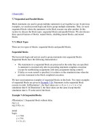
A module in Verilog consists of distinct parts, as shown in Figure 4-1
.
Figure 4-1. Components of a Verilog Module
A module definition always begins with the keyword module. The module name,
p
ort list, port declarations, and optional parameters must come first in a module
definition. Port list and port declarations are present only if the module has any
p
orts to interact with the external environment.The five components within a
module are: variable declarations, dataflow statements, instantiation of lower
modules, behavioral blocks, and tasks or functions. These components can be in
any order and at any place in the module definition. The endmodule statement
must always come last in a module definition. All components except module,
module name, and endmodule are optional and can be mixed and matched as per
design needs. Verilog allows multiple modules to be defined in a single file. The
modules can be defined in any order in the file.
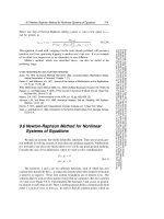
To understand the components of a module shown above, let us consider a simple
example of an SR latch, as shown in Figure 4-2
.
Figure 4-2. SR Latch
The SR latch has S and R as the input ports and Q and Qbar as the output ports.
The SR latch and its stimulus can be modeled as shown in Example 4-1
.
Example 4-1 Components of SR Latch
// This example illustrates the different components of a module
// Module name and port list
// SR_latch module
module SR_latch(Q, Qbar, Sbar, Rbar);
//Port declarations
output Q, Qbar;
input Sbar, Rbar;
// Instantiate lower-level modules
// In this case, instantiate Verilog primitive nand gates
// Note, how the wires are connected in a cross-coupled fashion.
nand n1(Q, Sbar, Qbar);
nand n2(Qbar, Rbar, Q);
// endmodule statement
endmodule
// Module name and port list
// Stimulus module
module Top;
// Declarations of wire, reg, and other variables
wire q, qbar;
reg set, reset;
// Instantiate lower-level modules
// In this case, instantiate SR_latch
// Feed inverted set and reset signals to the SR latch
SR_latch m1(q, qbar, ~set, ~reset);
// Behavioral block, initial
initial
begin
$monitor($time, " set = %b, reset= %b, q= %b\n",set,reset,q);
set = 0; reset = 0;
#5 reset = 1;
#5 reset = 0;
#5 set = 1;
end
// endmodule statement
endmodule
N
otice the following characteristics about the modules defined above:
• In the SR latch definition above , notice that all components described in
Figure 4-1
need not be present in a module. We do not find variable
declarations, dataflow (assign) statements, or behavioral blocks (always or
initial).
• However, the stimulus block for the SR latch contains module name, wire,
reg, and variable declarations, instantiation of lower level modules,
behavioral block (initial), and endmodule statement but does not contain por
t
list, port declarations, and data flow (assign) statements.
• Thus, all parts except module, module name, and endmodule are optional
and can be mixed and matched as per design needs.