Interfacing PIC Microcontrollers 31 potx
Bạn đang xem bản rút gọn của tài liệu. Xem và tải ngay bản đầy đủ của tài liệu tại đây (163.36 KB, 13 trang )
12
Assessment 8
1 Emitter arrow-head shows direction of current, NPN out from base, PNP in.
Vbe ~ 0.6 V. Typical current gain ϭ 100.
2 It is a voltage controlled current source, with high input impedance. Zero and +5 V
applied at the gate will switch it off and on.
3 Relay contacts have a low on resistance and high off resistance, but the operating coil
consumes significant power.
4 The DC motor needs a commutator to reverse the armature current on each half
revolution, so that the torque is developed in one direction only.
5 The thyristor switches direct current only, while the triac switches alternating current.
6 The software option can be implemented by the MCU toggling an output with a delay.
Alternatively, a separate hardware oscillator based on the 555 timer chip can be
switched on an off by the MCU.
7 Pulse Width Modulation uses a pulse waveform to control a current switch connected
to the load. If the ON time increases as a percentage of the overall period, the average
current in the load, and hence the power dissipated, increases.
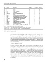
8 Bridge driver:
Answers to Assessment Questions
286
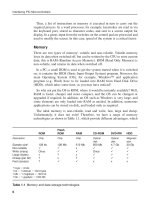
5.0
2.5
1.67
Input
Output
time
Noise spike fails to cause output to switch back as it
does not reach the upper switching level
Upper switch level
Lower switch level
M
PSU
+
_
Bridge
Else_IPM-BATES_Answers.qxd 7/11/2006 3:24 PM Page 286
The switches in the bridge (FETs) are turned on in pairs to allow the current to flow in
either direction in the motor.
9 The stepper motor has four sets
of coils which are activated in
pairs, to create a rotating magnetic
field which operates the rotor.
10 360/15 ϭ 24 steps/rev
Speed ϭ 100 steps/sec → 100/24 = 4.04 revs/s
11 200 slots/100 ms → 2000 slots/s → 2000/50 = 40 revs/s → 40ϫ60 ϭ 2400 rpm.
12 The DC motor drive is simpler in construction, more efficient, and higher speeds and
torque are possible, but it needs a feedback system for position control, and a gearbox
for low speeds. The stepper can positioned without feedback, and holds its position,
but is less inefficient and is complex to drive.
Assessment 9
1 No separate clock is sent with the data signal.
2 To increase the signal to noise ratio, and the distance sent, by increasing the signal
amplitude.
3 10 (8 data bits ϩ start ϩ stop)
4 TX (TXD), RX (RXD); there are separate send and receive lines.
5 Line attenuation and noise limits the distance in proportion to the sending amplitude. SPI
signals are sent at TTL levels (5 V) only, while RS232 uses amplitude up to 50 V p-p.
6 Slave select is a hardware input to an SPI device which enables slave transmission,
generated by the master controller. I
2
C uses software addressing, where the required
device and location are selected by an address sent on the serial data line.
7 SSPIF (synchronous serial interface interrupt flag) is set.
8 In I
2
C, a control code and address must be sent before the data, making up to 5 bytes
in all, plus control bits. In SPI, only data bits are sent as the slave device is selected in
hardware (slave select).
9 It holds the SDA line low for a bit cycle, which is detected by the master.
10 Only the start address is sent, and the memory automatically increments its internal
address pointer to the next location to fetch the next byte.
Answers to Assessment Questions
287
A
B
C
D
Else_IPM-BATES_Answers.qxd 7/11/2006 3:24 PM Page 287
11
12 Bits 7-4: Slave device select code (1 of 16)
Bits 4-1: Hardware chip select address (1 of 8)
Bit 0: Read/!Write bit
Assessment 10
1 Gold plated contacts, operation in a vacuum or inert gas (reed switch),
debouncing/snubbing with parallel capacitance/diodes, to reduce discharge and effect
of back emf with inductive loads.
2 If a position sensing grating has a graduated transmission or reflectance (eg sinusoidal)
when used with an optical sensor, intermediate positions can be calculated within each
grid cycle if the sensor provides a suitable analogue output.
3 The rate of change of the output divided by the rate of change of the input,
corresponding to the gradient of the characteristic.
4 Accuracy is the extent to which a measurement is consistent with the agreed standard,
precision is the smallest output change detectable; both may be expressed as a
percentage.
5 Any 3 of: temperature sensing resistor (metal film), semiconductor junction (p-type
and n-type silicon), thermocouple (dissimilar metals), thermistor (semiconductor),
resistance (platinum).
6 Strain gauges are connected as a bridge circuit to provide a differential output
which eliminates the large offset voltage when operated with a single supply, to
maximise the output amplitude and to provide inherent temperature
compensation.
7 50/10 ϭ 5
Answers to Assessment Questions
288
+12V
0V
-12V
Start Data bits Stop
bit
bit
time
Else_IPM-BATES_Answers.qxd 7/11/2006 3:24 PM Page 288
8
9 The instrumentation amplifier is a differential configuration, which eliminates offset in
the source voltage, has a high input impedance suitable for the high source impedance of
the strain gauge bridge, and has a high gain suited to the low sensitivity of the bridge.
10 100 kΩ
11 A potentiometer can be used to measure the angular position of a shaft, and is simple,
inexpensive and reasonably accurate. The digital method uses an incremental encoder,
where pulses are counted as the shaft moves from a home position; this is easy to
interface to an MCU, and is reliable.
12 Angular speed can be measured by a tachogenerator, which produces a voltage or
current in proportion to the speed of its input shaft; speed can then be measured via an
analogue input. The incremental encoder is used for speed measurement by measuring
the frequency of the pulses, and is reliable and easier to interface as it does not need an
analogue input.
Assessment 11
1 Parallel – block arrow, serial – single arrow, analogue – single arrow with labelling and
optional representation of waveform.
2 High frequency interference with other components, high power dissipation, unreliable
transmission down long connections.
3 Stable voltage, sufficient current, low noise
4 Selects an individual device to have access to a shared set of bus lines.
5 2
20
ϭ 1048576 locations → 1Mb assuming 8-bit locations.
6 The instruction set is not the same, and has a different instruction length.
Answers to Assessment Questions
289
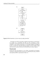
Input
Output
Gain
(gradient)
reduced
Positive
Offset
CHARACTERISTIC
Else_IPM-BATES_Answers.qxd 7/11/2006 3:24 PM Page 289
7 One-time programmable chips cannot be re-programmed with a new version of the
code.
8 The Intel 8051 MCU was developed from the 8085 CPU, and uses the same instruction
set as the Intel CPUs used in PCs.
9 It has a simplified instruction set and structure, and high clock rate, for faster program
execution.
10 Motorola 68000 CPU
11 Number of I/O pins, program memory size, peripherals available, data memory,
instruction set, developer expertise, cost.
12 ARM, Atmel, Motorola/Freescale, ST Microelectronics, Philips
1
Answers to Assessment Questions
290
Else_IPM-BATES_Answers.qxd 7/11/2006 3:24 PM Page 290
Index & Abbreviations
__CONFIG directive, 42, 39
24AA128 serial flash memory, 211
2s complement, 116
3-phase motor, 185
555 timer, 189
62256 RAM chip, 260
741 op-amp, 168
7-segment LED display, 88
8051 MCU, 275
AC motors, 185
ADC (analogue to digital converter) 141, 225
ADC 10-bit conversion, 145
ADC 8-bit conversion, 141
ADC clock, 143
ADC control register, 144
ADC conversion time, 143
ADC input availability, 266
ADC multiplexer, 143
ADC sample & hold, 166
ADC settling time, 143
ADCON0 (ADC control) register, 141
ADCON1 (ADC control) register, 28, 141
ADCSx (ADC frequency select) bits, 144
Add operations, 112, 123
ADDLW (add literal to W) instruction, 19
Address, 5
Address bus, 5, 11, 260
Address decoder, 260
Address label, 14, 19
Address latch, 260
ADDWF (add W to file) instruction, 19
ADFM (ADC result justify) bit, 144
ADIF (ADC interrupt) flag, 145
ADON (ADC enable) bit, 144
ADRESH (ADC result high byte), 141
ADRESL (ADC result low byte), 141
ADSCx (ADC control bits), 143
ALU (arithmetic & logic unit), 10
Amplifier, 149
Amplifier bandwidth, 149
Amplifier design, 149, 236
Amplifier feedback, 156
Amplifier gain, 156
Amplifier interfaces, 149
Amplifier offset, 155
Analogue input, 9, 28
Analogue output, 168
Analogue sensors, 225
ANDLW (AND literal with W) instruction, 19
ANDWF (AND W with file) instruction, 19
Animation (of simulated circuit), 63
ANSI ‘C’ language, 49
ANx analogue input, 142
Arbitrary waveform, 173
Architecture of MCU, 8
ARES PCB layout, 56
Arithmetic instructions, 20
Arithmetic processing, 112
ARM MCUs, 275
ASCII character codes, 91, 96, 101
ASCII to BCD conversion, 109
Assembler code, 37
Assembler directives, 41
Assembler syntax, 39
Assembly language, 12, 37
Else_IPM-BATES_index.qxd 7/12/2006 3:24 PM Page 291
291
Index & Abbreviations
292
Atmel AVR MCUs, 276
Autorouting, 72
BANKSEL directive, 22, 42
Base module, 249
Base of number, 102
Baud rate (RS232), 202
Baud rate generator, 203
BC (branch on carry) instruction, 42
BCD (binary coded decimal), 90, 104
BCD display (LED), 90
BCD to ASCII conversion, 109
BCD to binary conversion, 108
BCF (bit clear) instruction, 19
BiFET op-amp, 168
Binary numbers, 103
Binary to BCD conversion, 109, 134
Binary to decimal conversion, 106
Binary to hexadecimal conversion, 107
Bipolar op-amp, 168
Bipolar transistor, 179
Bit, 5
Bit label, 19
Bit test & skip, 21
BJT (bipolar junction transistor), 179
BJT equivalent circuit, 180
BJT interface, 180
BJT protection, 187
Block diagrams, 249
BNC (branch if not carry) instruction, 42
BNZ (branch if not zero) instruction, 42
BODEN (brown-out detect) bit, 17
Borrow bit, 26
Breakpoint (debugging), 65
BRGH (USART control) bit, 203
Brown-out reset, 17
Brushless DC motor, 185
BSF instruction, 19
BTFSC (bit test and skip if clear) instruction, 19
BTFSS (bit test and skip if set) instruction, 19
Bus contention, 264
Byte, 5
BZ (Branch if zero) instruction, 42
C compiler, 44
C program, 44
Calculator application, 121
Calculator keypad, 122
Calibration, 238
CALL (subroutine) instruction, 20, 23
Capacitance, 56, 81
Capacitor plate sensors, 229, 233
Capture mode, 131
Carry (C) flag/bit, 25, 112
CCP availability, 268
CCP1CON register, 130
CCPIF (capture & compare interrupt) flag, 130
CCPR1H (capture & compare preload high byte)
register, 129
CCPR1L (capture & compare preload low byte)
register, 129
CD-ROM (compact disk ROM), 6
CdS (cadmium disulphide photo-cell), 231
Centronics port, 7
Character variable type, 111
Characters, 101
Clear operation, 20
Clear watchdog timer, 18
CLKIN (clock in), 10
CLKOUT (clock out), 28
Clock, 11, 252
CLRF (clear file register) instruction, 19
CLRW (clear W register) instruction, 19
CLRWDT (clear watchdog timer) instruction,
17, 19
CMOS op-amp, 168
Code protection, 14
Column select, 87
Column weight, 102
COM (communication) port, 201
COMF (complement file register) instruction, 19
Comments, 14, 39
Comparator, 130, 165
Compare mode, 128
Complement operation, 20
Component properties, 59
Conditional branch, 21
CONFIG (configure MCU) directive, 14
Configuration word, 14
CONSTANT directive, 42
Control instructions, 21
Control lines, 5
Conversion (8-bit), 141
CPU (Central Processor Unit), 4
CPU data memory window, 61, 65
CPU register window, 61, 65
CR clock, 11, 57
CREN (USART receive enable) bit, 204
Crystal oscillator, 18
Current drivers, 179
Else_IPM-BATES_index.qxd 7/12/2006 3:24 PM Page 292
Index & Abbreviations
293
Current limiting resistor, 88
Current loop, 163
DAC (digital to analogue converter), 169
DAC filter, 170
DAC0808 parallel (PDAC), 169
Data, 5
Data bus, 5, 260
Data processing, 101
DC motor, 183
Debouncing, 81
Debugging, 63
DECF (decrement) instruction, 19
DECFSZ (decrement and skip if zero) instruction, 19
Decimal numbers, 102
Decimal to binary conversion, 107
Decoder, 5
Decoupling capacitors, 252
Decrement and skip if zero, 21
Decrement operation, 20
Default destination, 18
DEFINE directive, 42
Delay (software loop), 23, 46, 130
Denary numbers, 102
Destination address, 23
Difference amplifier, 155, 158
Differential gain, 149, 150
Differential voltage, 150
Digit carry, 26
Digital I/O, 7
Digital sensors, 223
Digital to analogue converter, 169
Diode temperature sensor, 230, 233
DIP (dual in-line package), 9
Divide operation, 115, 123
DT (define table) directive, 254
Dual supplies, 150
DVD (digital versatile disk), 6
E (LCD enable input), 91
ECAD (Electronic computer aided design), 55
Editing window, 58
EEPROM (electrically erasable programmable ROM),
11, 32
EEPROM size, 268, 269
Electromagnetic coil, 183
Embedded application, 4
Encoder, 224
END (source code) directive, 40, 42
ENDM (end macro) directive, 42
EPROM (erasable programmable read-only memory),
275
EQU (label equate) directive, 39
Error correction, 8
Exponent, 106
Extended memory, 264
Feedback capacitor, 160
FET (field effect transistor), 179, 182
FET channel, 182
FET gate, 183
File address, 11
File registers, 10
Flash ROM, 6, 10
Floating point (FP) numbers, 105
Floating point variable type, 110
Flowcharts, 45
Frequency response, 149, 160, 236
FSR (file select register), 11, 30
Full-step mode, 196
Gain, 149, 236
Gain & offset adjustment, 236
Gb (gigabyte), 6
Gerber file, 72
GIE (global interrupt enable) bit, 144
GO/DONE (ADC control) bit, 143
GOTO (label) instruction, 21
GPR (general purpose register), 10
Graphs (simulation), 69
Gray code, 224
Grounded load, 182
Half-step mode, 196
Hardware implementation, 70
Hardware multiplier availability, 268, 269
Hardware testing, 65
Hardware timers, 29
HC11 MCU, 275
HD44780 LCD controller, 91
HDD (hard disk drive), 6
Help files, 41
Hexadecimal numbers, 103
Hexadecimal to binary conversion, 107
HS (high speed) crystal, 18
Humidity sensor, 231, 235, 244
I/O (input/output) total, 268, 269
I
2
C (inter integrated circuit ) protocol, 210
I
2
C availability, 268, 269
Else_IPM-BATES_index.qxd 7/12/2006 3:24 PM Page 293
Index & Abbreviations
294
IC (integrated circuit) amplifier, 149
ICD (In-circuit debugging), 35, 73, 82, 252
IGFET (insulated gate FET), 182
INCF (increment) instruction, 19
INCFSZ (increment and skip if zero) instruction,19
In-circuit debugging, 16
In-circuit programming, 35
INCLUDE (source file) directive, 42
Include files, 42, 254
Increment & skip if zero, 21
Increment register, 20
INDF (indirect address) register, 30
Indirect addressing, 30
Inductance, 56
Inkjet printer, 224
Input resistance, 150, 156
Input/output (I/O), 4, 7, 252
Insruction length, 268, 269
Instruction, 5, 38
Instruction bus, 11
Instruction clock, 18
Instruction code, 13
Instruction decoder, 5, 11
Instruction register, 5, 11
Instruction set, 12, 14, 18
Instruction total, 268, 269
Instruction types, 20
Instrumentation amplifier, 161
INTCON (interrupt control register), 30
Integer variable type, 110
Integrated temperature sensor, 230
Internal oscillator speeds, 268, 269
Interpolation, 193
Interrupt control registers, 30
Interrupt priority, 31
Interrupt service routine, 30
Interrupts, 9, 23, 84, 129
Inverting amplifier, 157
IORLW (OR literal with W) instruction, 19
IORWF (OR W with file) instruction, 19
IRP (indirect address) bit, 30
ISIS schematic capture, 56
ISIS toolbars, 58
ISR (interrupt service routine), 23, 30, 84
Jump instructions, 21
kb (kilobyte), 6
Keypad, 87, 253
Keypad scanning, 87, 122
L297 stepper controller, 196
L298 stepper driver, 196
L6202 bridge driver, 193
Label equate, 14
Labels, 14
LCD (liquid crystal display), 90, 122, 253
LCD initialisation, 128
LDR (light dependent resistor), 231
LDR interface, 241
Least significant bit (LSB), 107
LED (light emitting diode), 11, 224
Level sensors, 229
Light sensors, 231, 235
Linear amplifier (op-amp), 150
Linear potentiometer, 229
LIST directive, 42
List file, 12, 14
Literal, 11, 14
LM016L LC display, 91
LM324 quad op-amp, 156
LM35 temperature interface, 240
Logic analyser, 67
Logic function, 56
Logic instructions, 20
Loudspeaker, 189
Low voltage programming, 17
LVDT (linear variable differential transformer), 228
Machine code, 14, 62
MACRO directive, 42
Macros, 41
Magnetic field, 183
Magnetic sensors, 229
Mantissa, 106
Mask programmed MCU, 267
MAX 232 serial line driver, 253
MAX directive, 42
Maximum value, 103
Mb (megabyte), 6
MCLR (master clear), 9, 57, 74
MCP4921 serial digital to analogue converter
(SDAC), 169, 173
MCU (Microcontroller Unit), 3
MCU properties, 60
MCU relative cost, 268, 269
MCU selection, 266
Memory, 4, 6, 253, 259, 266
Memory address, 13, 260
Memory size, 103
Memory system, 259
Else_IPM-BATES_index.qxd 7/12/2006 3:24 PM Page 294
Index & Abbreviations
295
Memory test, 260
Meters, 66
Microchip Inc., 4
Microcontroller, 3
Micro-switch, 224
Mnemonic, 13, 38
Mobile phone, 79
Most significant bit (MSB), 107
Motor, 183
Motor armature, 183
Motor brushes, 184
Motor commutator, 184
Motor interface, 189
Motor rotor, 184
Motorola/Freescale, 276
Move operation, 20
MOVF (move from file) instruction, 19
MOVLW ( move literal to W) instruction, 19
MOVWF ( move from W to file) instruction, 19
MPASM assembler, 12, 37
MPLAB development system, 12, 35, 252
MSR (mark space ratio), 190
MSSP (master synchronous serial port), 205
Multiply operation, 113, 123
NEG (negate file) instruction, 42
Negative feedback, 150
Negative numbers, 115
Netlist, 70
Nibble, 26
No operation, 21
NOEXPAND (macro) directive, 42
Noise immunity, 166
Non-inverting amplifier, 155
Non-volatile memory, 6
NOP (no operation) instruction, 20
NPN bipolar transistor, 179
Number conversion, 106
Number systems, 101
Numerical data, 101
Octal numbers, 104
Offset, 238
Ohms law, 55, 156
Op-amp (IC amplifier), 103, 149
Op-amp selection, 168
Op-code (operation code), 11
Open collector output, 166
Operand, 13
OPTION instruction, 22, 86
Opto-coupler, 187
Opto-detector, 224
Opto-isolator, 187, 224
Opto-sensor, 193
ORG (origin) directive, 42
OS (operating system), 6
Oscillator interface, 189
Oscilloscope, 66
OTP (one-time programmable) MCU, 267
Output resistance, 150
Overview window, 58
Page boundaries, 24
Parallel port, 7
PC (Personal Computer), 3
PC interface, 253
PCB (Printed circuit board), 56
PCB layout, 70
PCFGx (ADC control) bits, 143
PCL (program counter low byte) register, 23, 25
PCLATH (program counter high byte) latch, 22
PD (power down bit), 27
PEIE (peripheral interrupt enable) bit, 30
Pentium microprocessor, 3
Period measurement, 130
Peripheral control registers, 32
Peripheral interrupts, 30
PGM (program input), 17
Phototransistor, 224, 231
PIC 10FXXX MCUs, 267
PIC 12FXXX MCUs, 267
PIC 16F877 block diagram, 10
PIC 16F877 data sheet, 10
PIC 16F877 microcontroller, 3,8
PIC 16FXXX MCUs, 266
PIC 18FXXXX MCUs, 267
PIC output current, 57
Pick device, 59
PIE1 (peripheral interrupt enable register), 30
PIE2 (peripheral interrupt enable register), 30
Pin totals (PIC MCUs), 268, 269
Pin-out (P16F877), 9
PIR1 (peripheral interrupt flag register), 30
PIR2 (peripheral interrupt flag register), 30
PLC (program counter low), 22
PNP bipolar transistor, 179
Port A (P16F877), 9
Port B (P16F877), 9
Port C (P16F877), 9
Port control registers, 27
Else_IPM-BATES_index.qxd 7/12/2006 3:24 PM Page 295
Index & Abbreviations
296
Port D (P16F877), 9
Port data register, 7
Port E (P16F877), 9
Port initialisation, 27
Ports (P16F877), 27
Position control, 193
Position sensors, 228
Power dissipation, 181
Power interfacing, 185
Power outputs, 179
Power status bits, 27
Power supply, 10, 254
Power-up timer, 17
Pre-scaler, 29, 84
Pressure sensor, 231
Pressure sensor interface, 242
Processor (P16F877), 4
PROCESSOR (select) directive, 39, 42
Program (assembler), 12
Program counter, 5, 11, 22, 25
Program data table, 96
Program downloading, 73
Program execution, 11, 22
Program header, 62
Program layout, 40
Program memory, 5, 12
Program structure, 40
Programming, 9
Programming unit, 12, 35, 73
Proteus VSM (virtual system modelling), 56
Protocol, 7
Pseudocode, 46
Pull-up resistor, 80, 166
Pulse generation, 128
Push button, 80
Push button inputs, 11
PWM (pulse width modulation), 169
PWM availablity, 268
PWM speed control, 190
PWRTE (power up timer enable) bit, 17
R/W (read / write), 91
RAM (read/write memory), 6, 10
RAM size, 68, 269
Ratsnest, 72
RC (resistor/capacitor) clock, 9, 17, 62
RCREG serial receive register, 203
Reactance, 56
Reed switch, 224
Reference voltage, 157, 166
Reference voltage, 142
Refrigeration controller design, 270
Register bank, 10
Register bank select, 27
Register label, 19
Register operations, 20
Regulator, 254
Relay, 183, 186
Relay contacts, 184
Reset, 10, 252
RETFIE (return from interrupt) instruction, 19, 84
RETFIE (return from subroutine) instruction, 19, 23
RETLW (return with literal) instruction, 19, 96
RETURN (from subroutine) instruction, 20, 23
Return address, 21
Return from interrupt, 21, 24
RISC (reduced instruction set computer), 14
RLR (rotate left) instruction, 19
RMS (Root mean squared), 56
ROM (read-only memory), 6
Rotary potentiometer, 229
Rotate operation, 20
Row select, 87
RPx (register bank select) bits, 26
RRF (rotate right) instruction, 19
RS (LCD register select input), 91
RS232 interface, 253
RS232 line driver, 202
RS232 port, 8
RS232 serial protocol, 201
RS232 terminal, 204
RX (RS232 receive) line, 201
RXIF (USART receive) interrupt flag, 204
Sawtooth waveform, 170
Schematic capture, 58, 249
Schmitt trigger, 166
SCK (SPI serial clock), 207
SCL (I
2
C serial clock), 210
SDA (I
2
C serial data), 210
SDI (SPI serial data in), 207
SDO (SPI serial data out), 207
Segment labels, 90
Sensor, 223
Sensor accuracy, 228
Sensor amplifiers, 226
Sensor error, 228
Sensor interfacing, 223
Else_IPM-BATES_index.qxd 7/12/2006 3:24 PM Page 296
Index & Abbreviations
297
Sensor linearity, 227
Sensor offset, 227
Sensor precision, 228
Sensor reference level, 227
Sensor resolution, 228
Sensor sensitivity, 227
Sensor transfer function, 227
Sensor types, 228
Serial communications, 201
Serial DAC, 169
Serial line driver, 253
Serial memory, 253, 211
Serial port, 7
Servo-motor, 193
SET directive, 42
SFR (special function register), 10
Sign bit, 105
Signal generator, 131
Simulation, 55, 60
Simulation controls, 58
Sine waveform, 173
Skip instructions, 21
Slave port, 9
SLEEP instruction, 19, 38
Slotted wheel, 193
Software design, 44
Solenoid, 183
Source code, 12, 14
Source code debugging, 61, 64
Source code edit, 62
SPBRG (USART control) register, 203
Special function registers, 25
Special instructions, 41
Specification, 270
Speed measurement, 232
SPI (synchronous peripheral interface) protocol, 205
SPI availability, 268, 269
SPICE simulation, 55
Square waveform, 173
SS (SPI slave select line), 207
SSPBUF (synchronous serial port buffer), 208
SSPCON (synchronous serial port control register,
208
SSPEN (SSP enable bit), 208
SSPIF (SSP interrupt flag), 208
SSPSR (synchronous serial port shift register), 207
SSPSTAT (synchronous serial port status register),
208
ST Microelectronics, 276
Stack, 11, 23
Stack error, 23
Standard header file, 41
Status register, 11, 25
Stepper motor, 185, 195
Stepper sequence, 197
Strain gauge, 163, 231, 234
String variable type, 111
Structure charts, 47
SUBLW (subtract W from literal) instruction, 19
Subroutines, 22,40
Subtract operation, 113, 123
SUBWF (subtract W from file) instruction, 19
Summing amplifier, 157
SWAPF (swap nibbles) instruction, 19
Switch input, 79
Switching speed, 166
System design, 249
T0IF (timer zero interrrupt) flag, 28
T1CON (timer 1 control) register, 130
Tachogenerator, 193, 232
Temperature sensing resistor, 230, 234
Temperature sensors, 228, 233
Thermistor, 230, 234
Thermocouple, 230, 234
Thyristor control, 187
Timer (P16F877), 11, 29, 84
Timer availability, 268, 269
Timer0 (P16F877), 28, 84
Timer1 (P16F877), 29, 128
Timer2 (P16F877), 29
Timers, 11, 28, 84
Timer0 (timer zero) register, 28
Timing diagram, 69
TLC339 (quad comparator), 166
TMR0 (timer 0) register, 29
TMR1H (timer 1 high byte) register, 29, 129
TMR1L (timer 1 low byte) register, 29, 129
TMR2 (timer 2) register, 29
TO (time out) bit, 27
Transient response, 160
Triac control, 187
Triangular waveform, 173
Trigger comparator, 166
TRIS (data direction) instruction, 22
Tri-state buffers, 264
TSTF (test file register) instruction, 42
TX (RS232 transmit) line, 202
Else_IPM-BATES_index.qxd 7/12/2006 3:24 PM Page 297
Index & Abbreviations
298
TXIF (USART transmit interrupt) flag, 204
TXREG (serial transmit) register, 203
Ultrasonic transducers, 232
Unity gain buffer, 157
Universal amplifier, 158
USART (universal synchronous/asynchronous
receive/tramsmit), 8, 201
USART availability, 268, 269
USB (universal serial bus), 7, 201
Variable types, 110
VN66 FET, 182, 190
Volatile memory, 6
W (working register), 10
Watch window, 65
Watchdog timer, 17, 18
Weather station, 238
Window comparator, 168
Windows OS, 6
XORLW (exclusive OR literal with W) instruction, 19
XORWF (exclusive OR literal with W) instruction, 19
XT (crystal oscillator), 18
XTAL (crystal), 9, 18
Zener diode, 142
Zero (Z) flag, 21, 25
Else_IPM-BATES_index.qxd 7/12/2006 3:24 PM Page 298