Interfacing PIC Microcontrollers 22 ppsx
Bạn đang xem bản rút gọn của tài liệu. Xem và tải ngay bản đầy đủ của tài liệu tại đây (282.02 KB, 10 trang )
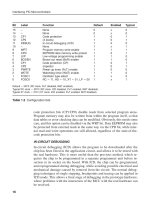
In Figure 8.9 (a), the stepper motor stator has 16 poles and the rotor 4
north poles which are attracted to the active pairs of rotor south poles. There
are four sets of windings, A, B, C, D, connected sequence around the stator.
These windings have their other ends connected to common terminals.
This gives a total of six connections to the motor, with two pairs of centre-
tapped windings. This allows the motor to be driven in different modes,
while keeping the number of connections to a minimum. In the test circuit,
the common terminals are connected to the power supply (ϩ12 V), and the
individual coil terminals driven from the sequencer (active low) (Figure
8.10).
In normal, full-step mode, the coil sets are activated in pairs (Figure 8.9 (b))
and the rotor moves half a pole per step, giving 24 steps per revolution. The
step size is then 360/24 ϭ 15°. This mode provides full torque but lower posi-
tional resolution. In half-step mode, the rotor moves by a quarter pole per step,
7.5°, providing twice as many steps per revolution, but less torque, since only
one coil pair is activated at a time.
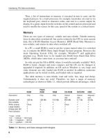
There are two chips forming the stepper drive interface. The L297 controller
provides the stepping sequence on outputs A, B, C and D, and the L298 full
bridge driver provides the drive current needed by the motor windings. The
drive mode (full or half step) is fixed in full step by tying the step mode select
input low. The active low reset is tied high. The MCU provides an enable sig-
nal, and selects the direction of rotation (clockwise (CW) or counter-clockwise
Interfacing PIC Microcontrollers
196
(a)
(b)
EN IN1 IN2 S1 S2 S3 S4 Motor
0 x x off off off off off
1 0 0 off ON off ON off
1 1 0 ON off off ON FORWARD
1 0 1 off ON ON off REVERSE
1 1 1 ON off ON off off
DC
Motor
Control
Logic
IN1
IN2
ENABLE
+12V
S1 S2
S3 S4
Vs
OUT1
OUT2
SENSE
Figure 8.9 Full bridge driver: (a) block diagram; (b) function table
Else_IPM-BATES_ch008.qxd 6/27/2006 2:25 PM Page 196
(CCW)), and the test program outputs clock pulses at a frequency of 20 Hz, so
that the stepping effect can be seen. When the stepper test is selected in the
MCU program, the motor rotates CW by default, with the ‘down’ button
changing the direction to CCW, and the ‘up’ button back to CW.
If the windings are left active in any position, that position can be held
against a load torque. Even when powered down, stepper motors tend to have
a residual torque, which holds the shaft in the last position selected, until an
external torque is applied. Thus, the motor can be moved and held to a set
angle, without feedback.
Power Outputs
197
(a)
(b)
Clock
A
B
C
D
One cycle = 4 clocks
B A A B
+ + + +
and repeat
D D C C
Stator
Rotor
A
C
B
D
A
C
B
D
A
C
B
D
A
C
B
D
S
COM
A
B
C
D
COM
N
N
N
N
Figure 8.10 Stepper motor operation: (a) windings sequence; (b) drive sequence (normal
mode)
Else_IPM-BATES_ch008.qxd 6/27/2006 2:25 PM Page 197
However, there is a lower limit to the step time required, which translates into
a maximum operating frequency and speed. If starting from stationary, the
speed may need to be increased gradually, until the rotor inertia gained will
allow the motor to run at its maximum speed. The speed also needs to be
ramped down when stopping, if correct position is to be maintained.
SUMMARY 8
• Power loads on MCU systems need a current amplifier or switch
• The bipolar transistor has current gain of 20–200 with low input resistance
• The FET provides a voltage controlled current with high input resistance
• The relay is an electromagnetic coil-operated switch
• The DC motor converts current into torque
• AC loads need a thyristor or triac to control the load current
• The speed of a DC motor can be controlled by PWM
• A DC servo provides analogue position feedback
• A shaft encoder provides digital speed and position feedback
• The stepper motor can be positioned without feedback
ASSESSMENT 8 Total (40)
1 State how an NPN and PNP resistor can be differentiated on a schematic, and
a notional value for the base-emitter volt drop and the typical current gain. (3)
2 Describe the useful characteristics of the VN66 FET. (3)
3 State two advantages and one disadvantage of the relay as an interface device. (3)
4 Explain why the DC motor needs a commutator, and the problems this causes. (3)
5 Explain the main functional difference between a thyristor and triac. (3)
6 Explain how an oscillator can be implemented in hardware or software. (3)
7 Explain how PWM allows the dissipation in a power load to be controlled. (3)
8 Explain, using a suitable diagram, how a bridge driver allows a DC motor to
drive in both directions. (3)
Interfacing PIC Microcontrollers
198
Else_IPM-BATES_ch008.qxd 6/27/2006 2:25 PM Page 198
9 Sketch the waveforms used to drive a typical stepper motor, and their meaning. (3)
10 A stepper motor has a step size of 15°. Its maximum step rate is 100 Hz.
Calculate the maximum speed in revs per second. (3)
11 Calculate the speed of a shaft in rpm if the MCU timer connected to a shaft
encoder with 50 slots counts 200 in 100 ms. (5)
12 Compare the advantages and disadvantages of the DC and stepper motor for
position control. (5)
ASSIGNMENTS 8
8.1 DC Motor Speed Control
Obtain two small DC permanent magnet motors, mount them in line and con-
nect the shafts together using a suitable flexible coupling, as a motor and
tachogenerator. Apply a variable voltage supply to one motor and note the out-
put voltage from the other (generator). Interface the motor to an MCU with
analogue input for unidirectional PWM drive. Write an application program to
operate the system under closed loop control. Drive the motor at a default mid-
range speed, while comparing the tacho output with a set value. Use push
buttons to increment and decrement the speed, and a two-digit display show-
ing the speed in revs per second.
8.2 Stepper Motor Characteristics
In the simulation software, select the standard stepper motor drive chip, and
connect up the interactive stepper motor. Operate the stepper drive clock
from a push button input and note the output sequence obtained. Draw
the input clock and outputs accurately on a time axis and compare with
Figure 8.9(b).
Obtain the data sheet for a stepper motor, and examine the torque/speed
characteristic, and specifications for holding torque. Explain the significance
of this characteristic in designing a robot arm with a stepper drive.
Consider the maximum speed of operation and load handling for a single
arm section, which is rotating in a vertical plane directly driven with a
stepper motor at one end and a load at the other, starting from the horizontal
position.
Power Outputs
199
Else_IPM-BATES_ch008.qxd 6/27/2006 2:25 PM Page 199
8.3 AC Power Control
Convert the block diagram for AC control (Figure 8.5(c)) into a simulation
circuit. Write a control program which samples the instantaneous AC supply
voltage and triggers the triac at around the peak voltage. Incorporate push
buttons to increment and decrement the power delivered. Display the output
current on the virtual oscilloscope.
Interfacing PIC Microcontrollers
200
Else_IPM-BATES_ch008.qxd 6/27/2006 2:25 PM Page 200
9
Serial Communication
Serial communication only requires one signal connection, so the total number
of hardware connections in a data link can be reduced to two or three, includ-
ing ground. A synchronous link may have a clock signal alongside the data, for
timing the transfer; an asynchronous one does not. This simplifies the wiring
where there are numerous peripheral devices for the MCU to communicate
with, or the connection is long distance. Within the microcontroller domain,
we tend to use the simpler forms of serial communications; the three PIC
16F877 serial interfaces described here are the USART, SPI (Serial Peripheral
Interface) and I
2
C (Inter-Integrated circuit).
USART
The Universal Synchronous Asynchronous Receiver Transmitter (USART)
provides the type of basic serial communication originally developed for dumb
terminals to communicate with mainframe computers; it was later adopted for
the COM port of the PC to interface to the mouse and other serial peripherals.
When converted into a higher transmission voltage, for distance transmission,
it is known as RS232. It can therefore, with additional interfacing, be used by
the PIC to communicate with a PC. It is therefore helpful for us that the PC re-
tains a standard COM port (9-pin D-type connector), even though, in general
use, it has been superseded by USB. Compared with the USART, USB is fast,
but complex, being more akin to a networking protocol; for this reason, it is
Else_IPM-BATES_ch009.qxd 6/29/2006 11:40 AM Page 201
201
not yet commonly provided in microcontrollers. RS232 is also the protocol
used to connect to the standard PIC programmer to a host PC.
PIC USART
In the PIC 16F877, the USART is accessed through pins RB6 and RB7. It has two
modes of operation, synchronous (using a separate clock signal) and asynchro-
nous (no clock connection). The asynchronous mode is probably used more often,
as other methods of synchronous transmission are available in the PIC, as we will
see. In asynchronous mode, RB6 acts as a data transmit (TX) output, and RB7 as
data receive input (RX) (16F877 data sheet, section 10.2). Data is usually trans-
mitted in 8-bit words (9 is an option), with the least significant bit sent first. The
receiver must sample the input at the same rate as the data is sent, so standard
clock (baud) rates are used. 9600 baud is used in our example here, meaning that
the bits are transmitted at about 10k bits/s. Separate transmit and receive lines are
used, so it is possible for these operations to be carried out simultaneously.
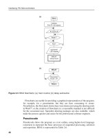
In the block diagram in Figure 9.1, the PIC is connected to a PC. The PIC
USART output itself operates at TTL voltages, and needs an external serial
line driver to convert its output into a higher symmetrical line voltage. This
is necessary because a simple baseband data signal is attenuated down a line,
due to the distributed resistance and capacitance of the cabling. The standard
RS232 interface operates with a higher line voltage so that the signal can be
Interfacing PIC Microcontrollers
202
Figure 9.1 USART: (a) connections to PC; (b) signal at PIC port
(a)
(b)
Idle
Start
Bit
Bit
0
Bit
1
Bit
2
Bit
3
Bit
4
Bit
5
Bit
6
Bit
7
Stop
Bit
Time
1
0
Bit period
PIC MCU
TX Transmit (RB6)
RX Receive (RB7)
HOST PC
RX
COM PORT
TX
Line
Driver
Interface
Else_IPM-BATES_ch009.qxd 6/29/2006 11:40 AM Page 202
transmitted further before being overcome by noise and interference. A typical
link distance for RS232 is around 10 m with symmetrical voltages of up to
ϩ/Ϫ25V. ϩ/Ϫ12 V is more typical. The signal is also inverted with respect to
the TTL version as shown in Figure 9.1 (b).
We will assume initially that the MCU is transmitting. The sender and receiver
have to be initialised to use the same baud rate, number of data bits (default 8)
and number of stop bits (default 1). The transmit (TX) output is high when idle
(external line negative). When the serial buffer register (TXREG) is written, the
data is automatically sent as follows. The start of the byte transmission is sig-
nalled by the line going low for one clock period (start bit). The following 8 bits
are then output from the transmit register, at intervals determined by the selected
baud rate. In the diagram, the bits are shown as both high and low, to indicate
that either is possible, depending on the particular data word. After the last data
bit, the line is taken high by the transmitter for one clock period (stop bit), and
that is the end of that transmission. The line is left high if there is no more data;
another word can be transmitted after a delay, or immediately following. The pro-
tocol is thus about as simple as it is possible to get. The data is often ASCII
coded, as the USART is frequently used to transmit character-based messages.
The receiver must be initialised to read in the data at the same baud rate. At
9600 baud, the bit period is about 100 s. When the falling edge of the start bit
is detected, the receiver must wait for 1.5 bit periods, then sample the line for
the first data bit (LSB), read the next after a further clock cycle and so on until
the set number of bits has been read in. The stop bit confirms the end of the
byte, and another transmission can start. An interrupt flag is used to signal to
the receiver MCU that there is data waiting. It must be read from RCREG be-
fore the next byte arrives.
The PIC data sheet has details of the operation of the USART interface. The
data is loaded into TXREG (FSR 19h) and transferred automatically to the
transmit register when it is ready to send. The shift clock is derived from a
baud rate generator, which uses the value in SPBRG (FSR 99h) in its counter.
This counter has a post-scaler which divides the output by 16 or 64, depend-
ing on the setting of control bit BRGH, so that all the standard baud rates can
be achieved using an 8-bit counter. The value to be pre-loaded into this regis-
ter to obtain a given baud rate is listed in tables in the MCU data. The error as-
sociated with each counter value and post-scaler setting is also specified, so
that the best option can be selected. The value 25d is used in the demo pro-
gram, with BRGH ϭ 1 giving an error of only 0.16% from the exact value for
9600 baud. However, a considerable error can be tolerated because sampling
only needs to be synchronised over 10 or 11 cycles at the receiver (start ϩ 8/9
data ϩ stop bit). It can be seen from these tables that the error can be up to
10%, and the system should still work.
Serial Communication
203
Else_IPM-BATES_ch009.qxd 6/29/2006 11:40 AM Page 203
Test System
The USART test system is shown in Figure 9.2. A simulated terminal is connected
to the USART port, and an oscilloscope allows the data signal to be observed. A
BCD-encoded 7-segment display is attached to Port D to display the data as they
are received by the MCU. It displays the decimal digit for a 4-bit pure binary input.
When the system is started, the PIC generates a user prompt for the virtual
terminal, which then waits for the user to input characters at the keyboard. The
terminal displays the input character and generates corresponding ASCII code
in RS232 format, which is received by the PIC. The code is read from RXREG,
and a BCD value is derived (subtract 30h) and output on the BCD display; only
numerical characters give the correct display.
The test program is outlined in Figure 9.3, and the source code in Program 9.1.
Once the USART module has been initialised, a code is transmitted and received
by simply writing or reading the port buffer registers. To send, the byte is moved
into TXREG, and the program then waits for the corresponding interrupt
flag, TXIF, to be set. To receive, the reception-enable bit, CREN, is set, and
the program waits for the interrupt bit, RCIF, to be set to indicate that a byte
has been received in RCREG. This is then copied to a suitable storage location
for processing. The USART module handles the received and transmit protocols
transparently.
Interfacing PIC Microcontrollers
204
Figure 9.2 USART simulation
Else_IPM-BATES_ch009.qxd 6/29/2006 11:40 AM Page 204
SPI
The Master Synchronous Serial Port (MSSP) module in the PIC provides
two main types of communication: SPI and I
2
C (usually pronounced I
squared C). These are used for communication between processors and slower
peripheral devices within a single system. SPI is simpler and faster, using a
hardware addressing system. I
2
C is more complex, with software addressing,
rather like a simple network protocol, so would be used in larger multi-
processor systems, and for access to serial memory and suitable transducer
interfaces.
SPI is a synchronous protocol, that is, it has a separate clock signal connec-
tion to control the send and receive operations (Figure 9.4). 8-bit data is
clocked in and out of the SPI shift register by a set of eight clock pulses, which
are either internally generated, or detected at the clock input. No start and stop
bits are necessary, and it is faster than the USART in any case, operating at up
to 5 MHz if the MCU clock is 20 MHz.
Serial Communication
205
SERCOM
Program to demonstrate USART operation by
outputting a fixed message to a simulated terminal,
reading numerical input from it, displaying it in BCD,
and sending it back to the terminal.
Initialise
Port D: BCD display outputs
USART: 8 bits, asynchronous mode
9600 baud (4MHz clock)
Enable
Main
Write message from ASCII table to terminal
REPEAT
Read input, display and echo
ALWAYS
Subroutines
Write message from ASCII table to terminal
REPEAT
Get character from table
Output to terminal
UNTIL all done
Read input, display and echo
Get input character
Convert to BCD and display
Echo character back to terminal
Figure 9.3 USART program outline
Else_IPM-BATES_ch009.qxd 6/29/2006 11:40 AM Page 205