Interfacing PIC Microcontrollers 28 potx
Bạn đang xem bản rút gọn của tài liệu. Xem và tải ngay bản đầy đủ của tài liệu tại đây (323.66 KB, 10 trang )
Interfacing PIC Microcontrollers
256
Program 11.1 Continued
;
; SUBROUTINES
;
; Routine to scan 3x4 phone key pad
; Returns ASCII code in W
; Output rows: RB2,RB4,RB5,RC5
; Input cols: RC0,RC1,RC2
;
keyin NOP
BANKSEL TRISC
MOVLW B'10010111' ; Port C code for
MOVWF TRISC ; rows and columns
BANKSEL PORTC
BSF PORTB,2 ; Set
BSF PORTB,4 ; rows
BSF PORTB,5 ; high
BSF PORTC,5 ; initially
BSF Cont,0 ; Counter not zero
CLRF Test ; No key
; Scan keyboard
again CLRW ; No key yet
BCF PORTB,2 ; Row 1
NOP ; wait
NOP
BTFSS PORTC,0 ; key pressed?
MOVLW '1' ; yes - load ASCII
BTFSS PORTC,1 ; next
MOVLW '2' ; etc
BTFSS PORTC,2 ;
MOVLW '3' ;
BSF PORTB,2 ; deselect row
;
BCF PORTB,4 ; second row
BTFSS PORTC,0
MOVLW '4'
BTFSS PORTC,1
MOVLW '5'
BTFSS PORTC,2
MOVLW '6'
BSF PORTB,4
;
BCF PORTB,5 ; third row
BTFSS PORTC,0
MOVLW '7'
BTFSS PORTC,1
MOVLW '8'
BTFSS PORTC,2
MOVLW '9'
BSF PORTB,5
;
BCF PORTC,5 ; fourth row
BTFSS PORTC,0
MOVLW '*'
BTFSS PORTC,1
MOVLW '0'
BTFSS PORTC,2
MOVLW '#'
BSF PORTC,5
; Test key
MOVWF Test ; get code
MOVF Test,F ; test it
BTFSS STATUS,Z ; if code found
GOTO once ; beep once
MOVF Key,W ; load key code and
RETURN ; if no key
; Check if beep done
once MOVF Cont,F ; beep already done?
BTFSC STATUS,Z
GOTO again ; yes - scan again
MOVF Test,W ; store key
MOVWF Key
; Beep
beep MOVLW 10 ; 10 cycles
MOVWF Cont
buzz BSF PORTB,0 ; one beep cycle
CALL onems ; 2ms
BCF PORTB,0
CALL onems
DECFSZ Cont ; last cycle?
GOTO buzz ; no
GOTO again ; yes
; End of keypad routine
Else_IPM-BATES_CH011.qxd 7/18/2006 1:27 PM Page 256
System Design
257
;
; Display input test voltage on top line of LCD
;
putdec BCF Select,RS ; set display command
mode
MOVLW 080 ; code to home cursor
CALL send ; output it to display
BSF Select,RS ; and restore data mode
; Convert digits to ASCII
MOVLW 030 ; load ASCII offset
ADDWF Huns ; convert hundreds to
ASCII
ADDWF Tens ; convert tens to ASCII
ADDWF Ones ; convert ones to ASCII
; Display voltage on line 1
CALL volmes ; Display text on line 1
MOVF Huns,W ; load hundreds code
CALL send ; and send to display
MOVLW '.' ; load point code
CALL send ; and output
MOVF Tens,W ; load tens code
CALL send ; and output
MOVF Ones,W ; load ones code
CALL send ; and output
MOVLW ' ' ; load space code
CALL send ; and output
MOVLW 'V' ; load volts code
CALL send ; and output
RETURN ; done
; Store voltage in serial memory
store BSF SSPCON,SSPEN ; Enable memory port
MOVF ADRESH,W ; Get voltage code
MOVWF SenReg ; Load it to write
CALL writmem ; Write it to memory
INCF LoReg ; Next location
BCF SSPCON,SSPEN ; Disable memory port
RETURN ; done
;
; Display key input on bottom line of LCD
;
putkey BCF Select,RS ; set display command
mode
MOVLW 0C0 ; code to home cursor
CALL send ; output it to display
BSF Select,RS ; and restore data mode
CALL keymes
RETURN ; done
;
; Display fixed messages
;
volmes CLRF Tabin ; Zero table pointer
next1 MOVF Tabin,W ; Load table pointer
CALL mess1 ; Get next character
MOVWF Temp ; Test data
MOVF Temp,F ; for zero
BTFSC STATUS,Z ; Last letter done?
RETURN ; yes - next block
CALL send ; no - display it
INCF Tabin ; Point to next letter
GOTO next1 ; and get it
;
keymes CLRF Tabin ; Zero table pointer
next2 MOVF Tabin,W ; Load table pointer
CALL mess2 ; Get next character
MOVWF Temp ; Test data
MOVF Temp,F ; for zero
BTFSC STATUS,Z ; Last letter done?
RETURN ; yes - next block
CALL send ; no - display it
INCF Tabin ; Point to next letter
GOTO next2 ; and get it
;
; Text strings for fixed messages
;
mess1 ADDWF PCL ; Set table pointer
DT "Volts = ",0 ; Text for display
mess2 ADDWF PCL ; Set table pointer
DT "Key = ",0 ; Text for display
;
Program 11.1 Continued
Else_IPM-BATES_CH011.qxd 7/18/2006 1:27 PM Page 257
The include routines must be stored in the same application folder with the
main source code, or the full file path to the folder must be given in the include
statement. For relatively small files, it is more convenient to copy them into
each application folder, as is the case here for the standard register label file
‘P16F877.INC’. These files were created by modifying the demonstration pro-
gram for each interface into the form of a subroutine. This entails deleting the
initialisation which is common with the main program, and using a suitable
label at the start (same as the include file name), and finishing with a RETURN.
This is a simple way to start building a library of utilities for the base hardware.
As can be seen, the software design philosophy is to make the main program
as concise as possible, so that ultimately it consists of a sequence of subrou-
tine calls. This makes the program easier to understand and debug. The sub-
routines in the main program are mainly concerned with operating the display,
Interfacing PIC Microcontrollers
258
;
; INCLUDED ROUTINES
;
; LCD DRIVER
; Contains routines:
; init: Initialises display
; onems: 1 ms delay
; xms: X ms delay
; Receives X in W
; send: sends a character to display
; Receives: Control code in W (Select,RS=0)
; ASCII character code in W (RS=1)
;
INCLUDE "LCDIS.INC"
;
;
; Convert 8 bits to 3 digit decimal
;
; Receives 8-bits in W
; Returns BCD diits in 'huns','tens','ones'
;
INCLUDE "CONDEC.INC";
;
;
; Read selected analogue input
;
; Receives channel number in W
; Returns 8-bit input in W
;
INCLUDE "ADIN.INC"
;
;
; SERIAL MEMORY DRIVER
; Write high address into 'HiReg' 00-3F
; Write low address into 'LoReg' 00-FF
; Load data send into 'SenReg'
; Read data received from 'RecReg'
;
; To initialise call 'inimem'
; To write call 'writmem'
; To read call 'readmem'
;
INCLUDE "SERMEM.INC"
;
;
END ; of source code
;
Program 11.1 Continued
Else_IPM-BATES_CH011.qxd 7/18/2006 1:27 PM Page 258
while the included routines are specific to particular interfaces. These are not
printed here, but are similar to the stand-alone demo programs, and can be in-
spected in the actual source code files provided.
Memory System
A conventional microprocessor system contains separate CPU and memory
chips. A similar arrangement can be used if we need extra memory in a PIC
system and there is no shortage of I/O pins. Parallel memory is inherently
faster than the serial memory as seen in Chapter 9, because the data is trans-
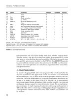
ferred 8 bits at a time. A system schematic is shown in Figure 11.3.
System Design
259
Figure 11.3 Parallel memory system
Else_IPM-BATES_CH011.qxd 7/18/2006 1:27 PM Page 259
Interfacing PIC Microcontrollers
260
Memory System Hardware
A pair of conventional 62256 32k RAM chips are used to expand the memory
to 64k bytes. Port C in the PIC 16F877 is used as a data bus, and Port D as an
address bus. In order to reduce the number of I/O pins needed for external
memory addressing, an address latch is used to store the high byte of the 15-
bit address (D7 unused). The address is output in two stages; the high byte is
latched, selecting the high address block; the low byte is then output direct to
the memory chips low address bits to select the location. If a block read is re-
quired, the high address can remain unchanged while a page of 256 bytes is ac-
cessed (low address 00-FF). The next page can then be selected if required. By
incrementing the high byte (page select) from 00 to 7F, the whole RAM range
can be accessed in each chip. Each chip is selected individually via an address
decoder, but the pairs of bytes from corresponding locations can be put to-
gether and processed as 16-bit data within the MCU.
Each RAM chip has eight data I/O pins (D0ϪD7) and 15 address pins
(A0ϪA14). This means that each location contains 8 bits, and there are 2
15
ϭ
32768 locations. An address code is fed in, and data for that address read or
written via the data pins. To select the chip, the Chip Enable (!CE) pin is taken
low. To write a location, an address code is supplied, data presented at D0ϪD7,
and the Write Enable (!WE) is pulsed low. To read data, the Output Enable
(!OE) is set active (low), along with the chip enable, and the data from the ad-
dress can then be read back.
The high address byte is temporarily stored in a ‘273 latch (8-bit register),
which is operated by a master reset and clock. The 7-bit high address is pre-
sented at the inputs, and the clock pulsed high to load the latch. The MCU
then outputs the low address direct to the memory low address pins, and the
combined address selects the location. In the test program, all addresses are
accessed in turn by incrementing the low address from 00 to FF for each high
address (memory page select). The memory can be organised as 64k ϫ 8
bytes or 32k ϫ 16-bit words.
Memory System Software
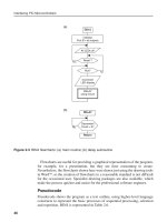
The test program (Program 11.2) writes a traditional checkerboard pattern to
the memory chips, placing the codes 01010101 (55h) and 10101010 (AAh) in
successive locations. Adjacent memory cells are therefore all set to opposite
voltage values, and any interaction between them, for example, due to charge
leakage, is more likely to show up. The memory is written and read, the data
retrieved, and compared with the correct value. If the write and read values do
not agree, an error LED is lit. A switch has been placed in the data line D0 so
that the error detection system can be tested in the simulation. When the switch
is open, data 0 will be written to all D0 bits (open circuit data input), so all the
Else_IPM-BATES_CH011.qxd 7/18/2006 1:27 PM Page 260
least significant bits of the test data 55h will be incorrect, with the value 54h
read back (Figures 11.4 and 11.5).
The system operates in a similar way as a conventional processor, with ad-
dress decoding hardware to organise the memory access. The address decoder
System Design
261
;;;;;;;;;;;;;;;;;;;;;;;;;;;;;;;;;;;;;;;;;;;;;;;;;;;;;;;;;;;;;;;;
; PARMEM.ASM MPB 6-9-05
;
;
; Parallel memory system
; Status: Complete
;
; PIC 16F877 operates with expansion memory RAM
; = 2 x 62256 32kb
; Control bits = Port B
; Data bus = Port C
; Address Bus = Port D
;
;;;;;;;;;;;;;;;;;;;;;;;;;;;;;;;;;;;;;;;;;;;;;;;;;;;;;;;;;;;;;;;;
PROCESSOR 16F877 ; define MPU
__CONFIG 0x3731 ; XT clock
; LABEL EQUATES ;;;;;;;;;;;;;;;;;;;;;;;;;;;;;;;;;;
INCLUDE "P16F877.INC" ; Standard labels
ConReg EQU 06 ; Port B = Control Register
DatReg EQU 07 ; Port C = Data Register
AddReg EQU 08 ; Port D = Address Register
HiAdd EQU 20 ; High address store
CLK0 EQU 0 ; RAM0 address buffer clock
CLK1 EQU 1 ; RAM1 address buffer clock
SelRAM EQU 2 ; RAM select bit
ResHi EQU 3 ; High address reset bit
WritEn EQU 4 ; Write enable bit
OutEn0 EQU 5 ; Output enable bit RAM0
OutEn1 EQU 6 ; Output enable bit RAM1
LED EQU 7 ; Memory error indicator
; Initialise ;;;;;;;;;;;;;;;;;;;;;;;;;;;;;;;;;;;;;;;;;;;;;;;;;;;;
ORG 0 ; Place machine code
NOP ; Required for ICD mode
BANKSEL TRISB ; Select bank 1
CLRF TRISB ; Control output bits
CLRF TRISC ; Data bus initially output
CLRF TRISD ; Address bus output
BANKSEL AddReg ; Select bank 0
CLRF DatReg ; Clear outputs initially
CLRF AddReg ; Clear outputs initially
BCF ConReg,CLK0 ; RAM0 address buffer clock
BCF ConReg,CLK1 ; RAM1 address buffer clock
BCF ConReg,SelRAM ; Select RAM0 initially
BCF ConReg,ResHi ; Reset high address latches
BSF ConReg,OutEn0 ; Disable output enable RAM0
BSF ConReg,OutEn1 ; Disable output enable RAM1
BSF ConReg,WritEn ; Disable write enable bit
BCF ConReg,LED ; Switch off error indicator
; MAIN LOOP ;;;;;;;;;;;;;;;;;;;;;;;;;;;;;;;;;;;;;;;;;;;;;;;;;;;;;
start CALL write ; test write to memory
CALL read ; test read from memory
SLEEP ; shut down
Program 11.2 Parallel memory program source code
Else_IPM-BATES_CH011.qxd 7/18/2006 1:27 PM Page 261
Interfacing PIC Microcontrollers
262
; SUBROUTINES ;;;;;;;;;;;;;;;;;;;;;;;;;;;;;;;;;;;;;;;;;;;;;;;;;;;
; Write checkerboard pattern to both RAMs ;;;;;;;;;;;;;;;;;;;;;;;
write BSF ConReg,ResHi ; Enable address latches
nexwrt MOVLW 055 ; checkerboard test data
MOVWF DatReg ; output on data bus
CALL store ; and write to RAM
MOVLW 0AA ; checkerboard test data
MOVWF DatReg ; output on data bus
CALL store ; and write to RAM
BTFSS ConReg,ResHi ; all done?
RETURN ; yes - quit
GOTO nexwrt ; no - next byte pair
; Check data stored ;;;;;;;;;;;;;;;;;;;;;;;;;;;;;;;;;;;;;;;;;;;;;
read NOP ; required for label
BANKSEL TRISC ; select bank 1
MOVLW 0FF ; all inputs
MOVWF TRISC ; at Port C
BANKSEL ConReg ; select default bank 0
BSF ConReg,ResHi ; Enable address latches
BCF ConReg,SelRAM ; select RAM0
BCF ConReg,OutEn0 ; set RAM0 for output
CALL nexred ; check data in RAM0
BSF ConReg,SelRAM ; select RAM1
BCF ConReg,OutEn1 ; set RAM1 for output
CALL nexred ; check data in RAM1
RETURN ; all done
; Load test data and check data
nexred MOVLW 055 ; load even data byte
CALL test ; check data
MOVLW 0AA ; load odd data byte
CALL test ; check data
BTFSS ConReg,ResHi ; all done?
RETURN ; yes - quit
GOTO nexred ; no - next byte pair
; Write data to RAM
store BCF ConReg,SelRAM ; Select RAM0
BCF ConReg,WritEn ; negative pulse
BSF ConReg,WritEn ; on write enable
BSF ConReg,SelRAM ; Select RAM1
BCF ConReg,WritEn ; negative pulse
BSF ConReg,WritEn ; on write enable
INCF AddReg ; next address
BTFSC STATUS,Z ; last address?
CALL inchi ; yes-inc. high address
RETURN ; no-next byte
; Test memory data
test MOVF DatReg,F ; read data
SUBWF DatReg,W ; compare data
BTFSS STATUS,Z ; same?
BSF ConReg,LED ; no - switch on LED
INCF AddReg ; yes - next address
BTFSC STATUS,Z ; last address in block?
CALL inchi ; yes-inc. high address
RETURN ; no - continue
; Select next block of RAM
inchi INCF HiAdd ; next block
BTFSC STATUS,Z ; all done?
GOTO alldon ; yes
MOVF HiAdd,W ; no - load high address
MOVWF AddReg ; output it
BSF ConReg,CLK0 ; clock it into latches
BSF ConReg,CLK1
BCF ConReg,CLK0
BCF ConReg,CLK1
CLRF AddReg ; reset low address
RETURN ; block done
alldon BCF ConReg,ResHi ; reset address latches
RETURN ; all blocks done
END ;;;;;;;;;;;;;;;;;;;;;;;;;;;;;;;;;;;;;;;;;;;;;;
Program 11.2 Continued
Else_IPM-BATES_CH011.qxd 7/18/2006 1:27 PM Page 262
System Design
263
PARMEM
Parallel memory test program
Writes test data to both RAM chips simultaneously
Checks test data in RAM0, then RAM1
Initialisation
Control Register = Port B = outputs
Bit 0 = RAM0 address buffer clock = 0
Bit 1 = RAM1 address buffer clock = 0
Bit 2 = RAM chip select bit = 0
Bit 3 = RAM address latch reset = 0
Bit 4 = RAM !Write enable = 1
Bit 5 = RAM0 !Output enable = 1
Bit 6 = RAM1 !Output enable = 1
Bit 7 = Error indicator LED = 0
Data Register = Port C = outputs = 00
Address Register = Port D = outputs = 00
Main
Write checkerboard pattern to both RAMs
Check data stored
Sleep
Subroutines
Write checkerboard pattern to both RAMs
REPEAT
Load data 55h
Write it to current memory location address
Load data AAh
Write it to current memory location address
UNTIL all locations done
Write it to current memory location address
Write data to RAM0
Write data to RAM1
Increment low address
IF last address, Select next page
Check data stored
Set data port for input
Select RAM0 for output
Check data in RAM
Select RAM1 for output
Check data in RAM
Check data in RAM
REPEAT
Load 55h
Compare with stored byte
(even)
Load AAh
Compare with stored byte
(odd)
UNTIL all done
Compare with stored byte
Compare bytes at current address
IF different, switch on error LED
Increment low address
IF end of page, Select next page
Select next page
Increment page select
IF last page done
reset high address latch
quit
Latch high address
Reset low address
Figure 11.4 Parallel memory program outline
Else_IPM-BATES_CH011.qxd 7/18/2006 1:27 PM Page 263
Interfacing PIC Microcontrollers
264
chip has three inputs CBA, which receive a binary select code from the proces-
sor. The corresponding output is taken low Ϫ for example, if binary 6 is input
(110), output Y6 is selected (low), while all the others stay high. This decoder
can generate 8-chip select signals, and if attached to the high address lines of
a processor, enable the memory chips in different ranges of addresses. In our
system here, only the least significant input (A) and two outputs (Y0, Y1) are
used, giving a minimal system. The additional address decoder outputs could
be used to control extra memory chips attached to the same set of address and
data lines.
The bus system operation depends on the presence of tri-state buffers at the
output of the RAM chips. These can be switched to allow data input (!CE &
!WE ϭ low), data output (!CE & !OE ϭ low) or disabled (!CE & !OE ϭ high).
In the disabled state, the outputs of the RAM are effectively disconnected from
the data bus. Only one RAM chip should be enabled at a time, otherwise there
will be contention on the bus Ϫ different data bytes present at the same time,
causing a data error.
Extended Memory System
If this system was extended using six more RAM chips, there would be
a total of 32k ϫ 8 bytes ϭ 256k. A 3-bit input would be required into the
address decoder (Port E could be used) to extend the chip selection system.
Figure 11.5 Memory test simulation screen
Else_IPM-BATES_CH011.qxd 7/18/2006 1:27 PM Page 264
The high address (page select) would still be 7 bits, and the location select 8
bits, giving a total address width of 18 bits. The address decoder chip also
has some enable inputs, which disable all outputs when active Ϫ this can be
used to extend the addressing system further.
A memory map has been constructed for this extended memory design
(Figure 11.6 (b)). It contains a total of 256k locations, divided into 8 blocks of
32k (one chip), each containing 128 pages of 256 bytes. In an extended system,
consideration must be given to the amount of current required by each input
connected to the busses. The high current output of the PIC is useful here, but
the standard digital outputs of the address latches have a more limited drive
System Design
265
(a)
(b)
Block
32k
Start
Address
End
Address
0 00000 07FFF
1 08000 0FFFF
2 10000 17FFF
3 18000 1FFFF
4 20000 27FFF
5 25000 2FFFF
6 30000 37FFF
7 38000 3FFFF
(c)
Block Add (E) Page Address (Port D latched) Location Address (Port D)
Bits
A17 A16 A15 A14 A13 A12 A11 A10 A9 A8 A7 A6 A5 A4 A3 A2 A1 A0
Allocation
RE2 RE1 RE0 RD6 RD5 RD4 RD3 RD2 RD1 RD0 RD7 RD6 RD5 RD4 RD3 RD2 RD1 RD0
MCU
Address Bus x 8
Block Address x 3
Data Bus x 8
RAM0
32k
CS0
RAM2
32k
CS2
CS1
RAM1
32k
High
Address
Latch 0
High
Address
Latch 1
CS3
RAM3
32k
RAM4
32k
CS4
RAM6
32k
CS6
CS5
RAM5
32k
CS7
RAM7
32k
Address
Decoder
Figure 11.6 256k Extended memory system: (a) block diagram; (b) memory map; (c) address
bit allocation
Else_IPM-BATES_CH011.qxd 7/18/2006 1:27 PM Page 265