Mold Design Fundamentals P3 pps
Bạn đang xem bản rút gọn của tài liệu. Xem và tải ngay bản đầy đủ của tài liệu tại đây (737.92 KB, 13 trang )
31
C
C
OR
E
OR
E
T
T
ECH
ECH
S
S
YSTE
M
YSTE
M
Mold.ppt
Air
Air
-
-
Trap and Gate Location
Trap and Gate Location
Air Bag Housing
thinner section
(0.5-0.8mm)
thicker section
(>10mm)
Racetrack Effect
Air-trap here
PLAY
When the plastic melt fills the mold, it displaces the air. The displaced air must
be removed quickly, or it may cause burn spot (due to the fast compression of
trapped air pocket by the low-thermal-conductivity polymer melt), or it may
restrict the flow of the melt into the mold cavity, resulting in incomplete filling
(short-shot problem).
Consider the injection-molding of a air bag housing. Notice that the part
consists of a thin central region and a thick rim around it. A single gate is
adopted in the original design. Most of the melt flow along the part side since the
section is thicker and the flow resistance is lower than that in the central thinner
region. That is, the melt races away along the thick rim while the central region is
filling at a slow rate. The filling along the rim is dominant and finally the melt
backfills the central region and cause an entrapment of air there. In this case an
air-trap problem is caused by the racetrack effect of melt flow.
To avoid the buring or incomplete filling associated with the entrapment of air,
proper venting is required. Venting is provided by the clearance between
knockout/vent pins and their holes, parting lines, as well as additional venting
slots (in general, 0.01 to 0.02mm deep and 3mm to 6mm wide).
Gate location is directly related to the consideration of venting location. In
general, the vent is located opposite the gate, area near the end of filling, or in the
air-trap position.
32
C
C
OR
E
OR
E
T
T
ECH
ECH
S
S
YSTE
M
YSTE
M
Mold.ppt
Viscous Heating and Gate Size
Viscous Heating and Gate Size
pinpoint gate (dia.=2mm)
Temperature (
o
C)
Gapwise Scale
inlet melt
temperature
temperature peak caused by
viscous heating effect
)Melt viscosity is reduced and flowability is improved by raising the
melt temperature via viscous heating effect
)Temperature raised <15
o
C (lower value for thermal sensitive material)
As the melt flows through the restricted gate, the flow velocity is sufficient high
and the melt is highly sheared in the narrow passage. This frictional (viscous)
heating would cause a raising in melt temperature. The temperature change is
related to the melt viscosity and the local shear rate.
The nomial wall shear rate in the gate is greater than 1000 sec
-1
and can reach as
high as 10
5
sec
-1
. At this high shear rate the viscosity may be reduced due to the
shear-thinning rheological character of polymer melt. The melt viscosity is
further reduced by the viscous heating in the gate region. The viscosity reduction
as the melt flows through the gate is important in improving the flowability of the
material.
A gate should be properly sized so that it could provide sufficient shearing and
viscous heating in order to achieve the greatest flow length possible. If the gate is
too large, it may freeze permaturely due to the insufficient viscous heating and
the dominant mold cooling effect. On the other hand, if the gate is too small,
filling process is highly restricted, leads to the overheating and thermal
degradation of part.
In general, the temperature change across the gate should be controlled within
the range of 15
o
C; if the material processed is thermal-sensitive, the range
should be smaller.
33
C
C
ORE
ORE
T
T
ECH
ECH
S
S
YSTE
M
YSTE
M
Mold.ppt
Gate Design vs. Part Shrinkage
Gate Design vs. Part Shrinkage
Gate Size
Part Shrinkage
Higher Packing
Lower Packing
Demolding
Less Shrinkage
Larger Shrinkage
Differential Shrinkage
°Back
Gate design is important not only in controlling the filling pattern of the mold
cavity, but also in the dimensional quality of molded part.
Smaller gates freeze off sooner. Once the gates frozen, there is no melt added
during the holding pressure stage, and the molded part will therefore shrink
more.
On the contrary, larger gates remain open longer. They freeze slowly and melt
continues to feed under holding pressure through the open gate, adding more
plastic as the melt shrinks in the cavity. Longer effective holding time and higher
holding pressure level of larger gates lead to smaller part shrinkage values.
In the mold cavity, the areas closer to the gating position are better packed than
the more remote areas, which may already have cooled down enough to prevent
additional melt to make up for volume contraction through shrinkage. The result
is that the areas near the gate shrink less than the areas farther away.
Besides, during the mold filling stage the polymer molecules undergo a
stretching that results in molecular orientation and anisotropic shrinkage
behavior: plastic materials tend to shrink more along the direction of flow (in-
flow shrinkage) compared to the direction perpendicular to flow (cross-flow
shrinkage), while the shrinkage behavior of reinforced material is restricted
along the fiber-orientation direction.
This differential shrinkage is the primary cause of part warpage.
34
C
C
ORE
ORE
T
T
ECH
ECH
S
S
YSTE
M
YSTE
M
Mold.ppt
Cooling System Design
Cooling System Design
molding
cooling
channels
•Layout
•Size
•Distance to Molding
•Coolant Flow Rate
•Coolant Temperature
•Type of Coolant
•Mold Material
The mold of thermoplastics receives the hot, molten plastic in its cavity and
cools it to solidify to the point of ejection. The mold is equiped with cooling
channels or cooling lines that remove heat released from the part via flowing
coolant. The mold temperature is controlled by regulating the temperature of
coolant and its flow rate through the cooling channels. Productivity (cycle time)
and quality (dimensional accuracy) of molded part depend heavily on the design
and efficiency of the cooling system.
High efficiency cooling system may cool down the part uniformly and quickly,
hence the cycle time can be shortened, this leads to an improvement of the
molding productivity.
The cooling channels should be spaced evenly to prevent uneven temper-ature
on the mold surface, they should be as close to the part surface as possible,
taking into account the strength of the mold material. The cooling channels are
connected to permit a uniform flow of the coolant, and they are thermostatically
controlled to maintain a given coolant temperature.
Even mold temperature distribution is important to ensure the dimensional
accuracy of molded part. Uneven mold temperature leads to unbalanced cooling
of part surface. The thermal stresses associated with the temperature profile
across the part thickness result in part warpage or distortion.
Design parameters involved in cooling system involves the type of coolant and
mold material, coolant flow rate, coolant temperature, distance and size of
cooling channels, and their layout.
3
5
C
C
ORE
ORE
T
T
ECH
ECH
S
S
YSTE
M
YSTE
M
Mold.ppt
Cooling Channel Layout vs.
Cooling Channel Layout vs.
Part Warpage
Part Warpage
Lower Cooling Rate
Higher Cooling Rate
Unbalanced Cooling
Demolding
Colder surface
Smaller Shrinkage
Hoter surface
Larger Shrinkage
Warpage of Injection-Molded Part
Uniform cooling throughout the part is critical to the dimensional accuracy of
molded part.
Consider the cooling of an injection-molded plate part by a poor-designed
cooling system. The top face of the part is cooled by three cooling channels, the
part surface temperature in higher due to the insufficient cooling; on the other
hand, the bottom face of the part is cooler since it is cooled by four cooling
channels (assume that all cooling channel has the same cooling efficiency).
The hotter top surface of the part will continue to shrink more than than the
cooler bottom surface after the gate frozen off and part ejection. This differential
shrinkage through the part thickness is caused by the differential cooling (
difference in the cooling rate between the cavity and the core) and would cause
the part to warp due to the unbalanced internal thermal stresses and their
associated bending moments as the part is ejected from the mold.
Non-uniform cooling plays a key role in the warpage behavior of molded part,
especially in the cases of flat moldings, such as disks (records, trays, etc). The
differential cooling problem can be minimized with proper mold cooling system
design.
3
6
C
C
OR
E
OR
E
T
T
ECH
ECH
S
S
YSTE
M
YSTE
M
Mold.ppt
Wall Thickness and Part Design
Wall Thickness and Part Design
q Flow Length/Wall Thickness Ratio (L/t Ratio)
) a measure of moldability of the part
()
L / t Ratio
Maximum Flow Length
From Gate to Rim
Average Wall Thickness
≡
⎛
⎝
⎜
⎞
⎠
⎟
L
t
L/t Ratio
0
100
200
300
Heavy-walled parts
easy to mold
Most parts
relatively easy to mold
Thin-walled part
Difficult to mold,
needs special considerations
Very-difficult-to-
mold part
needs special
equipment
An important measure of the moldability of a part design is its flow length/wall
thickness ratio (L/t ratio). The L/t ratio of a part is defined as its maximum flow
length from gate (the pressure source) to the farthest point (end point of filling),
to its average wall thickness.
A smaller values of the L/t ratio indicate a shorter flow length or thicker part
section, represent a smaller flow resistance and pressure loss, hence the parts are
easy to mold. On the other hand, thin-walled parts or parts with longer flow
length have larger L/t ratios and the molding is more difficult to carry out.
The L/t ratio of a given part can assist the part designer in determining the gate
locations, especially for parts of constant wall thickness. It’s rather difficult to
evaluate this value for a complicated part with variable wall thicknes, this
situation is further complicated by the fact that runner systems can consume a
significant portion of the mold’s pressure drop.
Many factors influence the L/t ratio of a given design, such as plastic materials
processed, melt temperature, mold temperature, maximum injection pressure, and
injection velocity, etc.
3
7
C
C
OR
E
OR
E
T
T
ECH
ECH
S
S
YSTE
M
YSTE
M
Mold.ppt
Maximum Flow Length of
Maximum Flow Length of
Plastic Materials
Plastic Materials
PC,PVC
Acetal
Nylon
Acrylic
ABS
PS
HDPE
PP
LDPE
25
36
38
33-38
45
51-63
57-63
63-70
70-76
0 1020304050607080
PC,PVC
Acetal
Nylon
Acrylic
ABS
PS
HDPE
PP
LDPE
(cm)
Maximum Flow Length in a 2.54mm(0.1in.) thick part
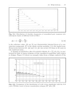
The flow of the plastic melt in the mold depends on various factors, such as the
plastic used, melt temperature, mold temperature, length and diameter of sprue
and runners, gate type, etc. In determining the minimum wall thickness of the
part, all these factors have to be considered.
The L/t ratio achieveable depends heavily on the type of plastic to be processed.
A high viscosity (low melt index) plastic such as polycarbonate (PC),
polysulfone (PSU), acrylic,etc., has a higher resistance to flow because of its
microstructure (cross linking, high molecular weight) and thus has a shorter
maximum flow length. It requires higher injection pressure to fill the mold cavity
with sufficient filling speed. For example, in a testing mold with a thickness of
2.54mm (0.1in.), the maximum flow length of PC is 25cm.
On the other hand, for easy-flow, low-viscosity plastics such as poly-propylene
(PP), polyethylene (PE), the maximum flow length is longer and the minimum
wall thickness that can be filled is smaller than for stiff-flowing materials.
Typical maximum flow length of general purpose grades of thermoplastics,
based on a cavity thickness of 2.54mm (0.1 in.) and conventional molding
techniques, are provided here to illustrate their processing properties. These data
are obtained from the spiral flow length experment and can be used as a reference
of moldability of various resin grades.
The actual maximum flow length of a plastic material depends on part design,
mold design, as well as the process variables.
38
C
C
OR
E
OR
E
T
T
ECH
ECH
S
S
YSTE
M
YSTE
M
Mold.ppt
Maximum Flow Length of
Maximum Flow Length of
Plastic Materials
Plastic Materials
Maximum Flow Length
Part Thickness
increasing
injection pressure
@constant injection speed,
mold/melt temperature
Maximum Flow Length
Part Thickness
increasing
melt/mold temperature
@constant injection pressure
injection speed
The maximum flow length achieveable for a particular plastic grade depends on
molding conditions of the experiments.
For instance, under a constant injection speed/mold temperature/melt
temperature condition, the flow length increases as the applied injection pressure
is increased because of the increasing driving force for mold filling. Thus easy-
to-flow materials require a lower injection pressure to fill the mold cavity with
sufficient filling speed.
Under a constant injection speed/injection pressure condition, the maximum
flow length of a given material increases as the mold temperature and/or the melt
temperature is raised. A plastic material has a longer flow length at higher
temperature because of its thermal-reduced melt viscosity.
These flow length data of plastic materials provide valuable information about
their flow behavior and processing properties. They are available from material
suppliers.
39
C
C
OR
E
OR
E
T
T
ECH
ECH
S
S
YSTE
M
YSTE
M
Mold.ppt
Wall Thickness of a Part
Wall Thickness of a Part
P
l
as
t
i
c
s
M
i
n. Wa
l
l
T
h
i
c
k
n
e
ss
(
mm
)
M
a
x
.Wa
l
l
T
h
i
c
k
n
e
ss
(
mm
)
S
u
g
g
e
s
t
e
dWa
l
l
T
h
i
c
k
n
e
ss
(
mm
)
P
O
M
0.4 3.0 1.6
A
B
S
0.75 3.0 2.3
A
c
r
y
l
i
c
/
P
M
M
A
0.6 6.4 2.4
C
e
l
l
u
l
os
e
0.6 4.7 1.9
T
e
f
l
on
0.25 12.7 0.9
N
y
l
on
0.4 3.0 1.6
P
C
1.0 9.5 2.4
Po
l
y
e
s
t
e
r
0.6 12.7 1.6
L
D
PE
0.5 6.0 1.6
H
D
PE
0.9 6.0 1.6
EV
A
0.5 3.0 1.6
PP
0.6 7.6 2.0
P
S
U
1.0 9.5 2.5
PP
O
0.75 9.5 2.0
PP
S
0.75 3.8 2.3
P
S
0.75 6.4 1.6
S
A
N
0.75 6.4 1.6
PV
C
-
R
i
g
i
d
1.0 9.5 2.4
P
U
0.6 38.0 12.7
S
u
r
l
y
n
0.6 19.0 1.6
The nominal minimum, maximum, and suggested wall thickness for various
plastic materials is listed here. The essential issue in determining the wall
thickness of a part is the flowability of polymer melt. The wall of a part should
allows plastic melt to flow properly under appropriate injection pressure. The
wall should permits effective transmission of packing/holding pressure during the
holding stage. Finally, the wall should withstand the internal/external loading
after the part is ejected from the mold cavity.
The allowable minimum wall thickness is smaller for easy-flow, low-viscosity
plastics such as polyethylene (PE) and polypropylene (PP). This value is larger
for polycarbonate (PC) and polysulfone (PSU) that are more viscous and stiff-
flow.
Typically, a thin-walled part can be arbitrarily defined as a part with a L/t ratio
greater than 200 or with wall thickness less than 1mm (t<1mm). In a thin-walled
part mold cooling effect is dominant and the part is rapidly cooled. Cycle time is
usually short (less than 10 sec). The injection pressure needed is higher for
proper filling and short-shot (incomplete filling) can be a problem.
A heavy-walled part can be defined as a part with a L/t ratio smaller than 100 or
with wall thickness more than 2mm (t>2mm). Filling is not a problem in a heavy
wall and the injection pressure needed is lower than that of the thin wall. Cycle
time is long, often longer than 20 sec.
Determining the proper part thickness is important to facilitate the processing
and ensure product strength.
40
C
C
OR
E
OR
E
T
T
ECH
ECH
S
S
YSTE
M
YSTE
M
Mold.ppt
Wall Thickness of a Part
Wall Thickness of a Part
q Empirical Equation
) t,L in mm
for easy -flow plastics: t = 0.6
L
100
0.5
for fair -flow plastics: t = 0.7
L
100
0.8
for stiff - flow plastics: t = 0.9
L
100
1.2
+
⎛
⎝
⎜
⎞
⎠
⎟
+
⎛
⎝
⎜
⎞
⎠
⎟
+
⎛
⎝
⎜
⎞
⎠
⎟
e.g.,PP,PE,Nylon
e.g.,POM,PMMA
e.g.,PC,PSU
An empirical equation is presented here to give an rough estimate of wall
thickness for a plastic part. For example, if polypropylene (PP) is used as the
molding compound, the wall thickness of a 50-cm long part will be:
wile for the stiff-flow polycarbonate (PC) the required wall thickness is:
the cooling time is about four times that of PP.
tmm=+
⎛
⎝
⎜
⎞
⎠
⎟
=06
500
100
05 33
tmm=+
⎛
⎝
⎜
⎞
⎠
⎟
=09
500
100
12 56
41
C
C
OR
E
OR
E
T
T
ECH
ECH
S
S
YSTE
M
YSTE
M
Mold.ppt
Part Wall Transition
Part Wall Transition
flow
t
Sharp/Stepped Transition:
poor design
flow
3t
Gradual Transition:
better design
thick-to-thin gating
flow
3t
Gradual Transition:
thin-to-thick gating
(not recommended)
flow
3t
Smooth/Tapered Transition:
best design
For a variable wall thickness part, the wall transition should be gradual to
ensure proper mold filling and part strength.
Consider the sharp or stepped transition case, the wall thickness undergoes a
step change in the part. During the filling stage the melt front chages its filling
velocity suddenly in the wall thickness transition region and a pressure loss is
caused by the flow contraction effect. The filling pattern in this design may result
in air entrapment and stress concentration problems.
A better design is to modify the stepped transition into a gradual transition
(usually tapered a transition length equal to three times the difference in
thickness). The melt velocity undergoes a gradual change as the cross section
contracts gradually. Pressure loss due to the gradual contraction is lower than that
of the stepped transition. High stress concentration around the transition region
can be avoided.
The best design is to vary the wall thickness as smooth as possible, usually a
tapered transition is adopted. Pressure loss and stress concentration can be
minimized in this design.
Note that the melt flow should be directed in the direction from “thick-to-thin”
whenever posible. The thicker section requires more packing/holding to
compensate for volume contraction and should be located closest to the gate. If
the flow direction is from thin section to thick section, the thinner section may
freeze off faster and hinder the packing of the thicker section, poor surface
finishes and sink mark/warpage problems may be caused.
42
C
C
OR
E
OR
E
T
T
ECH
ECH
S
S
YSTE
M
YSTE
M
Mold.ppt
Wall Thickness and Shrinkage
Wall Thickness and Shrinkage
local heavy section:poor
sink mark
Shrinkage voids
Use two short thick ribs:good
Use a long thin ribs:better
Core out the heavy section:better
Thin wall parts with heavy boss, ribs, rims, and/or other local heavy cross
sections usually is difficult to molding. Usually the poorly cooled heavy sections
will shrink more because the holding pressure will be ineffective after the thin
walls freeze and block the melt flow to these heavy sections. This can be often
seen by the sink marks on the surface behind these local heavy sections. Also, the
differential cooling and shrinkage of the thin and thick sections lead to warpage
of the molded part. When the cooled outer surface of the part is strong to resist
sinking and the inner hot melt cools and shrinks, shrinkage holes/voids will be
created within the plastic wall.
Thick ribs provide improved structural benefits and are easier to fill, however,
the level of sink associated with the thick ribs can be excessive. The sink mark
and internal shrinkage voids problems are significant if the rib wall thickness is
too heavy and/or if the rib base is wide.
Adopt a long but thin rib is a good strategy to improve the design. In practice,
rib wall thicknesses are typically 40%-80% as great as the wall from which they
extended, with a base radius values from 25%-40% of the wall thickness. The
specific rib designs are material dependent, and are influenced primarily by the
shrinkage behavior of the plastic material.
Alternative better design is to core out the heavy section, uniform wall thickness
can be obtained in this case. This results in cycle time reduction along with an
overall quality improvement.
43
C
C
OR
E
OR
E
T
T
ECH
ECH
S
S
YSTE
M
YSTE
M
Mold.ppt
Wall Thickness and Shrinkage
Wall Thickness and Shrinkage
original design
thick section
thick section
thin section
rib
sink mark
sink mark
sink mark
sink mark
part warpage
voids
stress concentration
better design
Thick walls in a part will fill easily, with less pressure, but will take a longer
time to cool and shrink more; on the other hand, thin walls require much higher
pressure to fill the cavity space at high speed and will not shrink as much as
heavy walls.
Thin wall parts with heavy boss, ribs, rims, and/or other local heavy cross
sections usually is difficult to molding. Problems such as sink marks, warpage,
and shrinkage voids may be caused if the part wall is not properly desinged.
When parts have both thick and thin sections, gating into the thick section is
preferred because it enables packing/holding of the heavy section, even if the
thinner sections have frozen off. The design can be further improved by coring
out heavy bosses and heavy sections, and by using ribs and edge stiffeners to
compensate for the loss in stiffness of a thinner section. A cored out section not
only shrinks less but also takes a shorter cooling time.
A properly design part, with even wall thickness and adequate ribbing, is
usually stronger and stiffer than a part with thicker and/or uneven walls. Saving
of material, reduction in part weight and cycle time, improvement in part quality
, etc., are the advantages obtained if we design the part carefully.