Mechanical Science Handbooks P2 ppt
Bạn đang xem bản rút gọn của tài liệu. Xem và tải ngay bản đầy đủ của tài liệu tại đây (924.32 KB, 20 trang )
Diesel Engine Fundamentals DOE-HDBK-1018/1-93 DIESEL ENGINES
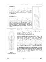
pushrods and rocker arms transfer the reciprocating motion generated by the camshaft
lobes to the valves and injectors, opening and closing them as needed. The valves are
maintained closed by springs.
As the valve is opened by the camshaft, it compresses the valve spring. The energy
stored in the valve spring is then used to close the valve as the camshaft lobe rotates out
from under the follower. Because an engine experiences fairly large changes in
temperature (e.g., ambient to a normal running temperature of about 190°F), its
components must be designed to allow for thermal expansion. Therefore, the valves,
valve pushrods, and rocker arms must have some method of allowing for the expansion.
This is accomplished by the use of valve lash. Valve lash is the term given to the "slop"
or "give" in the valve train before the cam actually starts to open the valve.
The camshaft is driven by
Figure 10 Diesel Engine Valve Train
the engine's crankshaft
through a series of gears
called idler gears and
timing gears. The gears
allow the rotation of the
camshaft to correspond or
be in time with, the
rotation of the crankshaft
and thereby allows the
valve opening, valve
closing, and injection of
fuel to be timed to occur at
precise intervals in the
piston's travel. To
increase the flexibility in
timing the valve opening,
valve closing, and injection
of fuel, and to increase
power or to reduce cost,
an engine may have one or
more camshafts. Typically,
in a medium to large V-type engine, each bank will have one or more camshafts per head.
In the larger engines, the intake valves, exhaust valves, and fuel injectors may share a
common camshaft or have independent camshafts.
Depending on the type and make of the engine, the location of the camshaft or shafts
varies. The camshaft(s) in an in-line engine is usually found either in the head of the
engine or in the top of the block running down one side of the cylinder bank. Figure 10
provides an example of an engine with the camshaft located on the side of the engine.
Figure 3 provides an example of an overhead cam arrangement as on a V-type engine.
On small or mid-sized V-type engines, the camshaft is usually located in the block at the
Rev. 0 ME-01
Page 11
DIESEL ENGINES DOE-HDBK-1018/1-93 Diesel Engine Fundamentals
center of the "V" between the two banks of cylinders. In larger or multi-camshafted V-
type engines, the camshafts are usually located in the heads.
Blower
The diesel engine's blower is part of the air intake system and serves to compress the
incoming fresh air for delivery to the cylinders for combustion. The location of the
blower is shown on Figure 2. The blower can be part of either a turbocharged or
supercharged air intake system. Additional information on these two types of blowers is
provided later in this module.
Diesel Engine Support Systems
A diesel engine requires five supporting systems in order to operate: cooling, lubrication, fuel
injection, air intake, and exhaust. Depending on the size, power, and application of the diesel,
these systems vary in size and complexity.
Engine Cooling
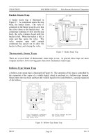
Figure 11 Diesel Engine Cooling System
Nearly all diesel
engines rely on a
liquid cooling
system to transfer
waste heat out of
the block and
internals as shown
in Figure 11. The
cooling system
consists of a closed
loop similar to that
of a car engine and
contains the
following major
components: water
pump, radiator or
heat exchanger,
water jacket (which
consists of coolant
passages in the
block and heads),
and a thermostat.
ME-01 Rev. 0
Page 12
Diesel Engine Fundamentals DOE-HDBK-1018/1-93 DIESEL ENGINES
Engine Lubrication
An internal combustion engine would not run for even a few minutes if the moving parts
were allowed to make metal-to-metal contact. The heat generated due to the tremendous
amounts of friction would melt the metals, leading to the destruction of the engine. To
prevent this, all moving parts ride on a thin film of oil that is pumped between all the
moving parts of the engine.
Once between the moving parts, the oil serves two purposes. One purpose is to lubricate
the bearing surfaces. The other purpose is to cool the bearings by absorbing the friction-
generated heat. The flow of oil to the moving parts is accomplished by the engine's
internal lubricating system.
Figure 12 Diesel Engine Internal Lubrication System
Rev. 0 ME-01
Page 13
DIESEL ENGINES DOE-HDBK-1018/1-93 Diesel Engine Fundamentals
Oil is accumulated and stored in the engine's oil pan where one or more oil pumps take
a suction and pump the oil through one or more oil filters as shown in Figure 12. The
filters clean the oil and remove any metal that the oil has picked up due to wear. The
cleaned oil then flows up into the engine's oil galleries. A pressure relief valve(s)
maintains oil pressure in the galleries and returns oil to the oil pan upon high pressure.
The oil galleries distribute the oil to all the bearing surfaces in the engine.
Once the oil has cooled and lubricated the bearing surfaces, it flows out of the bearing
and gravity-flows back into the oil pan. In medium to large diesel engines, the oil is also
cooled before being distributed into the block. This is accomplished by either an internal
or external oil cooler. The lubrication system also supplies oil to the engine's governor,
which is discussed later in this module.
Fuel System
All diesel engines require a method to store and deliver fuel to the engine. Because
diesel engines rely on injectors which are precision components with extremely tight
tolerances and very small injection hole(s), the fuel delivered to the engine must be
extremely clean and free of contaminants.
The fuel system must, therefore,
Figure 13 Diesel Engine Fuel Flowpath
not only deliver the fuel but also
ensure its cleanliness. This is
usually accomplished through a
series of in-line filters.
Commonly, the fuel will be
filtered once outside the engine
and then the fuel will pass through
at least one more filter internal to
the engine, usually located in the
fuel line at each fuel injector.
In a diesel engine, the fuel system
is much more complex than the
fuel system on a simple gasoline
engine because the fuel serves two
purposes. One purpose is
obviously to supply the fuel to run the engine; the other is to act as a coolant to the
injectors. To meet this second purpose, diesel fuel is kept continuously flowing through
the engine's fuel system at a flow rate much higher than required to simply run the
engine, an example of a fuel flowpath is shown in Figure 13. The excess fuel is routed
back to the fuel pump or the fuel storage tank depending on the application.
ME-01 Rev. 0
Page 14
Diesel Engine Fundamentals DOE-HDBK-1018/1-93 DIESEL ENGINES
Air Intake System
Because a diesel engine requires close tolerances to achieve its compression ratio, and
because most diesel engines are either turbocharged or supercharged, the air entering the
engine must be clean, free of debris, and as cool as possible. Turbocharging and
supercharging are discussed in more detail later in this chapter. Also, to improve a
turbocharged or supercharged engine's efficiency, the compressed air must be cooled after
being compressed. The air intake system is designed to perform these tasks.
Air intake systems vary greatly
Figure 14 Oil Bath Air Filter
from vendor to vendor but are
usually one of two types, wet or
dry. In a wet filter intake system,
as shown in Figure 14, the air is
sucked or bubbled through a
housing that holds a bath of oil
such that the dirt in the air is
removed by the oil in the filter.
The air then flows through a
screen-type material to ensure any
entrained oil is removed from the
air. In a dry filter system, paper,
cloth, or a metal screen material is
used to catch and trap dirt before
it enters the engine (similar to the
type used in automobile engines).
In addition to cleaning the air, the
intake system is usually designed
to intake fresh air from as far
away from the engine as
practicable, usually just outside of
the engine's building or enclosure.
This provides the engine with a
supply of air that has not been
heated by the engine's own waste
heat.
The reason for ensuring that an engine's air supply is as cool as possible is that cool air
is more dense than hot air. This means that, per unit volume, cool air has more oxygen
than hot air. Thus, cool air provides more oxygen per cylinder charge than less dense,
hot air. More oxygen means a more efficient fuel burn and more power.
Rev. 0 ME-01
Page 15
DIESEL ENGINES DOE-HDBK-1018/1-93 Diesel Engine Fundamentals
After being filtered, the air is routed by the intake system into the engine's intake
manifold or air box. The manifold or air box is the component that directs the fresh air
to each of the engine's intake valves or ports. If the engine is turbocharged or
supercharged, the fresh air will be compressed with a blower and possibly cooled before
entering the intake manifold or air box. The intake system also serves to reduce the air
flow noise.
Turbocharging
Turbocharging an engine occurs when the engine's own exhaust gasses are forced
through a turbine (impeller), which rotates and is connected to a second impeller
located in the fresh air intake system. The impeller in the fresh air intake system
compresses the fresh air. The compressed air serves two functions. First, it
increases the engine's available power by increasing the maximum amount of air
(oxygen) that is forced into each cylinder. This allows more fuel to be injected
and more power to be produced by the engine. The second function is to increase
intake pressure. This improves the scavenging of the exhaust gasses out of the
cylinder. Turbocharging is commonly found on high power four-stroke engines.
It can also be used on two-stroke engines where the increase in intake pressure
generated by the turbocharger is required to force the fresh air charge into the
cylinder and help force the exhaust gasses out of the cylinder to enable the engine
to run.
Supercharging
Supercharging an engine performs the same function as turbocharging an engine.
The difference is the source of power used to drive the device that compresses the
incoming fresh air. In a supercharged engine, the air is commonly compressed
in a device called a blower. The blower is driven through gears directly from the
engines crankshaft. The most common type of blower uses two rotating rotors
to compress the air. Supercharging is more commonly found on two-stroke
engines where the higher pressures that a supercharger is capable of generating
are needed.
Exhaust System
The exhaust system of a diesel engine performs three functions. First, the exhaust system
routes the spent combustion gasses away from the engine, where they are diluted by the
atmosphere. This keeps the area around the engine habitable. Second, the exhaust system
confines and routes the gasses to the turbocharger, if used. Third, the exhaust system
allows mufflers to be used to reduce the engine noise.
ME-01 Rev. 0
Page 16
Diesel Engine Fundamentals DOE-HDBK-1018/1-93 DIESEL ENGINES
Operational Terminology
Before a detailed operation of a diesel engine can be explained, several terms must be defined.
Bore and Stroke
Bore and stroke are terms used to define the size of an engine. As previously stated, bore
refers to the diameter of the engine's cylinder, and stroke refers to the distance the piston
travels from the top of the cylinder to the bottom. The highest point of travel by the
piston is called top dead center (TDC), and the lowest point of travel is called bottom
dead center
(BDC). There are 180
o
of travel between TDC and BDC, or one stroke.
Engine Displacement
Engine displacement is one of the terms used to compare one engine to another.
Displacement refers to the total volume displaced by all the pistons during one stroke.
The displacement is usually given in cubic inches or liters. To calculate the displacement
of an engine, the volume of one cylinder must be determined (volume of a cylinder =
(πr
2
)h where h = the stroke). The volume of one cylinder is multiplied by the number
of cylinders to obtain the total engine displacement.
Degree of Crankshaft Rotation
All events that occur in an engine are related to the location of the piston. Because the
piston is connected to the crankshaft, any location of the piston corresponds directly to
a specific number of degrees of crankshaft rotation.
Location of the crank can then be stated as XX degrees before or XX degrees after top
or bottom dead center.
Firing Order
Firing order refers to the order in which each of the cylinders in a multicylinder engine
fires (power stroke). For example, a four cylinder engine's firing order could be 1-4-3-2.
This means that the number 1 cylinder fires, then the number 4 cylinder fires, then the
number 3 cylinder fires, and so on. Engines are designed so that the power strokes are
as uniform as possible, that is, as the crankshaft rotates a certain number of degrees, one
of the cylinders will go through a power stroke. This reduces vibration and allows the
power generated by the engine to be applied to the load in a smoother fashion than if they
were all to fire at once or in odd multiples.
Rev. 0 ME-01
Page 17
DIESEL ENGINES DOE-HDBK-1018/1-93 Diesel Engine Fundamentals
Compression Ratio and Clearance Volume
Clearance volume is the volume remaining in the cylinder when the piston is at TDC.
Because of the irregular shape of the combustion chamber (volume in the head) the
clearance volume is calculated empirically by filling the chamber with a measured amount
of fluid while the piston is at TDC. This volume is then added to the displacement
volume in the cylinder to obtain the cylinders total volume.
An engine's compression ratio is determined by taking the volume of the cylinder with
piston at TDC (highest point of travel) and dividing the volume of the cylinder when the
piston is at BDC (lowest point of travel), as shown in Figure 15. This can be calculated
by using the following formula:
Compression Ratio
displacement volume clearance volume
clearance volume
Figure 15 Compression Ratio
Horsepower
Power is the amount of work done per unit time or the rate of doing work. For a diesel
engine, power is rated in units of horsepower. Indicated horsepower is the power
transmitted to the pistons by the gas in the cylinders and is mathematically calculated.
ME-01 Rev. 0
Page 18
Diesel Engine Fundamentals DOE-HDBK-1018/1-93 DIESEL ENGINES
Brake horsepower refers to the amount of usable power delivered by the engine to the
crankshaft. Indicated horsepower can be as much as 15% higher than brake horsepower.
The difference is due to internal engine friction, combustion inefficiencies, and parasitic
losses, for example, oil pump, blower, water pump, etc.
The ratio of an engine's brake horsepower and its indicated horsepower is called the
mechanical efficiency of the engine. The mechanical efficiency of a four-cycle diesel is
about 82 to 90 percent. This is slightly lower than the efficiency of the two-cycle diesel
engine. The lower mechanical efficiency is due to the additional friction losses and power
needed to drive the piston through the extra 2 strokes.
Engines are rated not only in horsepower but also by the torque they produce. Torque
is a measure of the engine's ability to apply the power it is generating. Torque is
commonly given in units of lb-ft.
Rev. 0 ME-01
Page 19
DIESEL ENGINES DOE-HDBK-1018/1-93 Diesel Engine Fundamentals
Summary
The important information in this chapter is summarized below.
Diesel Engines Summary
The compression ratio is the volume of the cylinder with piston at
TDC divided by the volume of the cylinder with piston at BDC.
Bore is the diameter of the cylinder.
Stroke is the distance the piston travels from TDC to BDC, and is
determined by the eccentricity of the crankshaft.
The combustion chamber is the volume of space where the fuel air mixture
is burned in an engine. This is in the cylinder of the engine.
The following components were discussed and identified on a drawing.
a. Piston and rod
b. Cylinder
c. Blower
d. Crankshaft
e. Intake ports or valve(s)
f. Exhaust ports or valve(s)
g. Fuel injector
ME-01 Rev. 0
Page 20
DOE-HDBK-1018/1-93
Diesel Engine Fundamentals FUNDAMENTALS OF THE DIESEL CYCLE
FUNDAMENTALS OF THE DIESEL CYCLE
Diesel engines operate under the principle of the internal combustion engine.
There are two basic types of diesel engines, two-cycle and four-cycle. An
understanding of how each cycle operates is required to understand how to
correctly operate and maintain a diesel engine.
EO 1.3 EXPLAIN how a diesel engine converts the chemical energy
stored in the diesel fuel into mechanical energy.
EO 1.4 EXPLAIN how the ignition process occurs in a diesel engine.
EO 1.5 EXPLAIN the operation of a 4-cycle diesel engine, including
when the following events occur during a cycle:
a. Intake
b. Exhaust
c. Fuel injection
d. Compression
e. Power
EO 1.6 EXPLAIN the operation of a 2-cycle diesel engine, including
when the following events occur during a cycle:
a. Intake
b. Exhaust
c. Fuel injection
d. Compression
e. Power
The Basic Diesel Cycles
A diesel engine is a type of heat engine that uses the internal combustion process to convert the
energy stored in the chemical bonds of the fuel into useful mechanical energy. This occurs in
two steps. First, the fuel reacts chemically (burns) and releases energy in the form of heat.
Second the heat causes the gasses trapped in the cylinder to expand, and the expanding gases,
being confined by the cylinder, must move the piston to expand. The reciprocating motion of
the piston is then converted into rotational motion by the crankshaft.
Rev. 0 ME-01
Page 21
DOE-HDBK-1018/1-93
FUNDAMENTALS OF THE DIESEL CYCLE Diesel Engine Fundamentals
To convert the chemical energy of the fuel into useful mechanical energy all internal combustion
engines must go through four events: intake, compression, power, and exhaust. How these
events are timed and how they occur differentiates the various types of engines.
All diesel engines fall into one of two categories, two-stroke or four-stroke cycle engines. The
word cycle refers to any operation or series of events that repeats itself. In the case of a four-
stroke cycle engine, the engine requires four strokes of the piston (intake, compression, power,
and exhaust) to complete one full cycle. Therefore, it requires two rotations of the crankshaft,
or 720° of crankshaft rotation (360° x 2) to complete one cycle. In a two-stroke cycle engine
the events (intake, compression, power, and exhaust) occur in only one rotation of the crankshaft,
or 360°.
Timing
In the following discussion of the diesel cycle it is important to keep in mind the time
frame in which each of the actions is required to occur. Time is required to move exhaust
gas out of the cylinder and fresh air in to the cylinders, to compress the air, to inject fuel,
and to burn the fuel. If a four-stroke diesel engine is running at a constant 2100
revolutions per minute (rpm), the crankshaft would be rotating at 35 revolutions, or
12,600 degrees, per second. One stroke is completed in about 0.01429 seconds.
The Four-Stoke Cycle
In a four-stroke engine the camshaft is geared so that it rotates at half the speed of the crankshaft
Figure 16 Scavenging and Intake
(1:2). This means that the crankshaft must make two complete revolutions before the camshaft
will complete one revolution. The following section will describe a four-stroke, normally
aspirated, diesel engine having both intake and exhaust valves
with a 3.5-inch bore and 4-inch stroke with a 16:1 compression
ratio, as it passes through one complete cycle. We will start on
the intake stroke. All the timing marks given are generic and
will vary from engine to engine. Refer to Figures 10, 16, and 17
during the following discussion.
Intake
As the piston moves upward and approaches 28° before
top dead center (BTDC), as measured by crankshaft
rotation, the camshaft lobe starts to lift the cam follower.
This causes the pushrod to move upward and pivots the
rocker arm on the rocker arm shaft. As the valve lash is
taken up, the rocker arm pushes the intake valve
downward and the valve starts to open. The intake
stroke now starts while the exhaust valve is still open.
The flow of the exhaust gasses will have created a low
ME-01 Rev. 0
Page 22
DOE-HDBK-1018/1-93
Diesel Engine Fundamentals FUNDAMENTALS OF THE DIESEL CYCLE
pressure condition within the cylinder and will help pull in the fresh air charge as shown
in Figure 16.
The piston continues its upward travel through top dead center (TDC) while fresh air
enters and exhaust gasses leave. At about 12° after top dead center (ATDC), the
camshaft exhaust lobe rotates so that the exhaust valve will start to close. The valve is
fully closed at 23° ATDC. This is accomplished through the valve spring, which was
compressed when the valve was opened, forcing the rocker arm and cam follower back
against the cam lobe as it rotates. The time frame during which both the intake and
exhaust valves are open is called valve overlap (51° of overlap in this example) and is
necessary to allow the fresh air to help scavenge (remove) the spent exhaust gasses and
cool the cylinder. In most engines, 30 to 50 times cylinder volume is scavenged through
the cylinder during overlap. This excess cool air also provides the necessary cooling
effect on the engine parts.
As the piston passes TDC and begins to travel down the cylinder bore, the movement of
the piston creates a suction and continues to draw fresh air into the cylinder.
Compression
At 35° after bottom dead center (ABDC), the intake
Figure 17 Compression
valve starts to close. At 43° ABDC (or 137° BTDC),
the intake valve is on its seat and is fully closed. At
this point the air charge is at normal pressure (14.7 psia)
and ambient air temperature (~80°F), as illustrated in
Figure 17.
At about 70° BTDC, the piston has traveled about 2.125
inches, or about half of its stroke, thus reducing the
volume in the cylinder by half. The temperature has now
doubled to ~160°F and pressure is ~34 psia.
At about 43° BTDC the piston has traveled upward 3.062
inches of its stroke and the volume is once again halved.
Consequently, the temperature again doubles to about
320°F and pressure is ~85 psia. When the piston has
traveled to 3.530 inches of its stroke the volume is again
halved and temperature reaches ~640°F and pressure 277 psia. When the piston has
traveled to 3.757 inches of its stroke, or the volume is again halved, the temperature
climbs to 1280°F and pressure reaches 742 psia. With a piston area of 9.616 in
2
the
pressure in the cylinder is exerting a force of approximately 7135 lb. or 3-1/2 tons of
force.
Rev. 0 ME-01
Page 23
DOE-HDBK-1018/1-93
FUNDAMENTALS OF THE DIESEL CYCLE Diesel Engine Fundamentals
The above numbers are ideal and provide a good example of what is occurring in an
engine during compression. In an actual engine, pressures reach only about 690 psia.
This is due primarily to the heat loss to the surrounding engine parts.
Fuel Injection
Figure 18 Fuel Injection
Fuel in a liquid state is injected into the cylinder at
a precise time and rate to ensure that the
combustion pressure is forced on the piston neither
too early nor too late, as shown in Figure 18. The
fuel enters the cylinder where the heated
compressed air is present; however, it will only
burn when it is in a vaporized state (attained
through the addition of heat to cause vaporization)
and intimately mixed with a supply of oxygen.
The first minute droplets of fuel enter the
combustion chamber and are quickly vaporized.
The vaporization of the fuel causes the air
surrounding the fuel to cool and it requires time
for the air to reheat sufficiently to ignite the
vaporized fuel. But once ignition has started, the
additional heat from combustion helps to further
vaporize the new fuel entering the chamber, as long as oxygen is present. Fuel
injection starts at 28° BTDC and ends at 3° ATDC; therefore, fuel is injected for
a duration of 31°.
Power
Both valves are closed, and the fresh air charge has
Figure 19 Power
been compressed. The fuel has been injected and
is starting to burn. After the piston passes TDC,
heat is rapidly released by the ignition of the fuel,
causing a rise in cylinder pressure. Combustion
temperatures are around 2336°F. This rise in
pressure forces the piston downward and increases
the force on the crankshaft for the power stroke as
illustrated in Figure 19.
The energy generated by the combustion process is
not all harnessed. In a two stroke diesel engine,
only about 38% of the generated power is
harnessed to do work, about 30% is wasted in the
form of heat rejected to the cooling system, and
about 32% in the form of heat is rejected out the
exhaust. In comparison, the four-stroke diesel
engine has a thermal distribution of 42% converted
ME-01 Rev. 0
Page 24
DOE-HDBK-1018/1-93
Diesel Engine Fundamentals FUNDAMENTALS OF THE DIESEL CYCLE
to useful work, 28% heat rejected to the cooling system, and 30% heat rejected
out the exhaust.
Exhaust
Figure 20 Exhaust
As the piston approaches 48° BBDC, the cam of the
exhaust lobe starts to force the follower upward, causing
the exhaust valve to lift off its seat. As shown in
Figure 20, the exhaust gasses start to flow out the exhaust
valve due to cylinder pressure and into the exhaust
manifold. After passing BDC, the piston moves upward
and accelerates to its maximum speed at 63° BTDC. From
this point on the piston is decelerating. As the piston
speed slows down, the velocity of the gasses flowing out
of the cylinder creates a pressure slightly lower than
atmospheric pressure. At 28° BTDC, the intake valve
opens and the cycle starts again.
The Two-Stroke Cycle
Like the four-stroke engine, the two-stroke engine must go
through the same four events: intake, compression, power, and exhaust. But a two-stroke engine
requires only two strokes of the piston to complete one full cycle. Therefore, it requires only one
rotation of the crankshaft to complete a cycle. This means several events must occur during each
stroke for all four events to be completed in two strokes, as opposed to the four-stroke engine
where each stroke basically contains one event.
In a two-stroke engine the camshaft is geared so that it rotates at the same speed as the
crankshaft (1:1). The following section will describe a two-stroke, supercharged, diesel engine
having intake ports and exhaust valves with a 3.5-inch bore and 4-inch stroke with a 16:1
compression ratio, as it passes through one complete cycle. We will start on the exhaust stroke.
All the timing marks given are generic and will vary from engine to engine.
Exhaust and Intake
At 82° ATDC, with the piston near the end of its power stroke, the exhaust cam begins
to lift the exhaust valves follower. The valve lash is taken up, and 9° later (91° ATDC),
the rocker arm forces the exhaust valve off its seat. The exhaust gasses start to escape
into the exhaust manifold, as shown in Figure 21. Cylinder pressure starts to decrease.
After the piston travels three-quarters of its (down) stroke, or 132° ATDC of crankshaft
rotation, the piston starts to uncover the inlet ports. As the exhaust valve is still open, the
uncovering of the inlet ports lets the compressed fresh air enter the cylinder and helps
cool the cylinder and scavenge the cylinder of the remaining exhaust gasses (Figure 22).
Commonly, intake and exhaust occur over approximately 96° of crankshaft rotation.
Rev. 0 ME-01
Page 25
DOE-HDBK-1018/1-93
FUNDAMENTALS OF THE DIESEL CYCLE Diesel Engine Fundamentals
At 43° ABDC, the camshaft starts to close the exhaust valve. At 53° ABDC (117°
BTDC), the camshaft has rotated sufficiently to allow the spring pressure to close the
exhaust valve. Also, as the piston travels past 48°ABDC (5° after the exhaust valve starts
closing), the intake ports are closed off by the piston.
Figure 21 2-Stroke Exhaust Figure 22 2-Stroke Intake
Compression
After the exhaust valve is on its seat (53° ATDC), the temperature and pressure begin to
rise in nearly the same fashion as in the four-stroke engine. Figure 23 illustrates the
compression in a 2-stroke engine. At 23° BTDC the injector cam begins to lift the
injector follower and pushrod. Fuel injection continues until 6° BTDC (17 total degrees
of injection), as illustrated in Figure 24.
ME-01 Rev. 0
Page 26
DOE-HDBK-1018/1-93
Diesel Engine Fundamentals FUNDAMENTALS OF THE DIESEL CYCLE
Figure 23 2-Stroke Compression Figure 24 2-Stroke Fuel Injection
Power
Figure 25 2-Stroke Power
The power stroke starts after the piston passes TDC.
Figure 25 illustrates the power stroke which continues
until the piston reaches 91° ATDC, at which point the
exhaust valves start to open and a new cycle begins.
Rev. 0 ME-01
Page 27
DOE-HDBK-1018/1-93
FUNDAMENTALS OF THE DIESEL CYCLE Diesel Engine Fundamentals
Summary
The important information in this chapter is summarized below.
Fundamentals of the Diesel Cycle Summary
Ignition occurs in a diesel by injecting fuel into the air charge which has been
heated by compression to a temperature greater than the ignition point of the
fuel.
A diesel engine converts the energy stored in the fuel's chemical bonds into
mechanical energy by burning the fuel. The chemical reaction of burning the
fuel liberates heat, which causes the gasses to expand, forcing the piston to
rotate the crankshaft.
A four-stroke engine requires two rotations of the crankshaft to complete one
cycle. The event occur as follows:
Intake - the piston passes TDC, the intake valve(s) open and the fresh air is
admitted into the cylinder, the exhaust valve is still open for a few degrees
to allow scavenging to occur.
Compression - after the piston passes BDC the intake valve closes and the
piston travels up to TDC (completion of the first crankshaft rotation).
Fuel injection - As the piston nears TDC on the compression stroke, the
fuel is injected by the injectors and the fuel starts to burn, further heating
the gasses in the cylinder.
Power - the piston passes TDC and the expanding gasses force the piston
down, rotating the crankshaft.
Exhaust - as the piston passes BDC the exhaust valves open and the
exhaust gasses start to flow out of the cylinder. This continues as the piston
travels up to TDC, pumping the spent gasses out of the cylinder. At TDC
the second crankshaft rotation is complete.
ME-01 Rev. 0
Page 28
DOE-HDBK-1018/1-93
Diesel Engine Fundamentals FUNDAMENTALS OF THE DIESEL CYCLE
Fundamentals of the Diesel Cycle Summary (Cont.)
A two-stroke engine requires one rotation of the crankshaft to complete one
cycle. The events occur as follows:
Intake - the piston is near BDC and exhaust is in progress. The intake
valve or ports open and the fresh air is forced in. The exhaust valves or
ports are closed and intake continues.
Compression - after both the exhaust and intake valves or ports are closed,
the piston travels up towards TDC. The fresh air is heated by the
compression.
Fuel injection - near TDC the fuel is injected by the injectors and the fuel
starts to burn, further heating the gasses in the cylinder.
Power - the piston passes TDC and the expanding gasses force the piston
down, rotating the crankshaft.
Exhaust - as the piston approaches BDC the exhaust valves or ports open
and the exhaust gasses start to flow out of the cylinder.
Rev. 0 ME-01
Page 29
DIESEL ENGINE SPEED, DOE-HDBK-1018/1-93 Diesel Engine Fundamentals
FUEL CONTROLS, AND PROTECTION
DIESEL ENGINE SPEED, FUEL CONTROLS,
AND PROTECTION
Understanding how diesel engines are controlled and the types of protective
instrumentation available is important for a complete understanding of the
operation of a diesel engine.
EO 1.7 DESCRIBE how the mechanical-hydraulic governor on a
diesel engine controls engine speed.
EO 1.8 LIST five protective alarms usually found on mid-sized and
larger diesel engines.
Engine Control
The control of a diesel engine is accomplished through several components: the camshaft, the fuel
injector, and the governor. The camshaft provides the timing needed to properly inject the fuel,
the fuel injector provides the component that meters and injects the fuel, and the governor
regulates the amount of fuel that the injector is to inject. Together, these three major components
ensure that the engine runs at the desired speed.
Fuel Injectors
Each cylinder has a fuel injector designed to meter and inject fuel into the cylinder at the proper
instant. To accomplish this function, the injectors are actuated by the engine's camshaft. The
camshaft provides the timing and pumping action used by the injector to inject the fuel. The
injectors meter the amount of fuel injected into the cylinder on each stroke. The amount of fuel
to be injected by each injector is set by a mechanical linkage called the fuel rack. The fuel rack
position is controlled by the engine's governor. The governor determines the amount of fuel
required to maintain the desired engine speed and adjusts the amount to be injected by adjusting
the position of the fuel rack.
Each injector operates in the following manner. As illustrated in Figure 26, fuel under pressure
enters the injector through the injector's filter cap and filter element. From the filter element the
fuel travels down into the supply chamber (that area between the plunger bushing and the spill
deflector). The plunger operates up and down in the bushing, the bore of which is open to the
fuel supply in the supply chamber by two funnel-shaped ports in the plunger bushing.
ME-01 Rev. 0
Page 30