Optical Networks: A Practical Perspective - Part 9 ppt
Bạn đang xem bản rút gọn của tài liệu. Xem và tải ngay bản đầy đủ của tài liệu tại đây (745.01 KB, 10 trang )
50 PROPAGATION OF SIGNALS IN OPTICAL FIBER
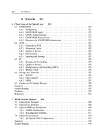
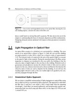
Figure 2.1 Cross section and longitudinal section of an optical fiber showing the core
and cladding regions, a denotes the radius of the fiber core.
theory model based on solving Maxwell's equations. We then devote the rest of the
chapter to understanding the basics of chromatic dispersion and fiber nonlinearities.
Designing advanced systems optimized with respect to these parameters is treated in
Chapter 5.
2.1
2.1.1
Light Propagation in Optical Fiber
An optical fiber consists of a cylindrical
core
surrounded by a
cladding.
The cross
section of an optical fiber is shown in Figure 2.1. Both the core and the cladding
are made primarily of silica (SiO2), which has a refractive index of approximately
1.45. The
refractive index
of a material is the ratio of the speed of light in a vacuum
to the speed of light in that material. During the manufacturing of the fiber, certain
impurities (or dopants) are introduced in the core and/or the cladding so that the
refractive index is slightly higher in the core than in the cladding. Materials such as
germanium and phosphorous increase the refractive index of silica and are used as
dopants for the core, whereas materials such as boron and fluorine that decrease the
refractive index of silica are used as dopants for the cladding. As we will see, the
resulting higher refractive index of the core enables light to be guided by the core,
and thus propagate through the fiber.
Geometrical Optics Approach
We can obtain a simplified understanding of light propagation in optical fiber using
the so-called
ray theory
or
geometrical optics
approach. This approach is valid when
the fiber that is used has a core radius a that is much larger than the operating
wavelength k. Such fibers are termed
multimode,
and first-generation optical com-
munication links were built using such fibers with a in the range of 25-100/~m and
)~ around 0.85 ~m.
2.1 Light Propagation in Optical Fiber
51
II
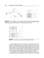
Figure
2.2 Reflection and refraction of light rays at the interface between two media.
In the geometrical optics approach, light can be thought of as consisting of a
number of "rays" propagating in straight lines within a material (or medium) and
getting reflected and/or refracted at the interfaces between two materials. Figure 2.2
shows the interface between two media of refractive index n l and n2. A light ray
from medium 1 is incident on the interface of medium 1 with medium 2. The
angle
of incidence
is the angle between the
incident ray
and the normal to the interface
between the two media and is denoted by 01. Part of the energy is reflected into
medium 1 as a
reflected ray,
and the remainder (neglecting absorption) passes into
medium 2 as a
refracted ray.
The
angle of reflection 01r
is the angle between the
reflected ray and the normal to the interface; similarly, the
angle of refraction
02 is
the angle between the refracted ray and the normal. The laws of geometrical optics
state that
Olr ~ O1
and
n 1 sin
O1
n 2 sin 02. (2.1)
Equation (2.1) is known as
Snell's law.
As the angle of incidence
01
increases, the angle of refraction 02 also increases.
If nl > n2, there comes a point when 02 = 7r/2 radians. This happens when
01
sin -1
n2/nl.
For larger values of 01, there is no refracted ray, and all the energy from
the incident ray is reflected. This phenomenon is called
total internal reflection.
The
smallest angle of incidence for which we get total internal reflection is called the
critical angle
and equals sin -1
n2/nl.
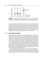
Simply stated, from the geometrical optics viewpoint, light propagates in optical
fiber due to a series of total internal reflections that occur at the core-cladding
interface. This is depicted in Figure 2.3. In this figure, the coupling of light from the
medium outside (taken to be air with refractive index no) into the fiber is also shown.
52 PROPAGATION OF SIGNALS IN OPTICAL FIBER
Figure 2.3 Propagation of light rays in optical fiber by total internal reflection.
It can be shown using Snell's law (see Problem 2.1) that only those light rays that are
incident at an angle
00 < 0~ nax=
sin -i V/n12 - n22 (2.2)
no
at the air-core interface will undergo total internal reflection at the Core-cladding
interface and will thus propagate. Such rays are called
guided rays,
and 0~ nax is called
the
acceptance angle.
The refractive index difference n l - n2 is usually small, and
it is convenient to denote the fractional refractive index difference (nl -
nz)/nl
by
A. For small A, 0~ nax ~ sin -1 nl,/~ As an example, if A = 0.01 which is a typical
n0 "
value for (multimode) fiber, and nl = 1.5, a typical value for silica, assuming we are
coupling from air, so that no = 1, we obtain 0~ nax ~ 12 ~
Owing to the different lengths of the paths taken by different guided rays, the
energy in a narrow (in time) pulse at the input of the fiber will be spread out over a
larger time interval at the output of the fiber. A measure of this time spread, which
is called
intermoclal dispersion,
is obtained by taking the difference in time, ~T,
between the fastest and the slowest guided rays. We will see later that by suitably
designing the fiber, intermodal dispersion can be significantly reduced (graded-index
fiber) and even eliminated (single-mode fiber).
We now derive an approximate measure of the time spread due to intermodal
dispersion. Consider a fiber of length L. The fastest guided ray is the one that travels
along the center of the core and takes a time
Tf = Lnl/c
to traverse the fiber, c being
the speed of light in a vacuum. The slowest guided ray is incident at the critical angle
on the core-cladding interface, and it can be shown that it takes a time T~ =
Ln 2/cn2
to propagate through the fiber. Thus
L n21A.
,~T=Ts-rf=
c n2
2.1 Light Propagation in Optical Fiber
53
How large can ~T be before it begins to matter? That depends on the bit rate
used. A rough measure of the delay variation 8T that can be tolerated at a bit rate
of B b/s is half the bit period 1/2B s. Thus intermodal dispersion sets the following
limit:
Ln 2 1
8T - A < ~. (2.3)
c n2 2B
The capacity of an optical communication system is frequently measured in terms
of the
bit rate-distance product.
If a system is capable of transmitting x_Mb/s over
a distance of y km, it is said to have a bit rate-distance product of
xy
(Mb/s)-km.
The reason for doing this is that usually the same system is capable of transmitting
x' Mb/s over y~ km providing
x~y ~ < xy;
thus only the product of the bit rate and
the distance is constrained. (This is true for simple systems that are limited by loss
and/or intermodal dispersion, but is no longer true for systems that are limited by
chromatic dispersion and nonlinear effects in the fiber.) From (2.3), the intermodal
dispersion constrains the bit rate-distance product of an optical communication link
to
ln2 c
BL<-~
2n 2 A
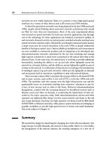
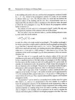
For example, if A = 0.01 and nl = 1.5(~ n2), we get
BL
< 10 (Mb/s)-km. This limit
is plotted in Figure 2.4.
Note that 0~ ax increases with increasing A, which causes the limit on the bit
rate-distance product to decrease with increasing A. The value of A is typically
chosen to be less than 1% so as to minimize the effects of intermodal dispersion,
and since 0~ ~x is consequently small, lenses or other suitable mechanisms are used
to couple light into the fiber.
The fiber we have described is a
step-index
fiber since the variation of the refrac-
tive index along the fiber cross section can be represented as a function with a step
at the core-cladding interface. However, almost all multimode fibers used today are
graded-index
fibers, and the refractive index decreases gradually, or continuously,
from its maximum value at the center of the core to the value in the cladding at the
core-cladding interface. This has the effect of reducing 8T because the rays traversing
the shortest path through the center of the core encounter the highest refractive index
and travel slowest, whereas rays traversing longer paths encounter regions of lower
refractive index and travel faster. For the optimum graded-index profile (which is
very nearly a quadratic decrease of the refractive index in the core from its maximum
value at the center to its value in the cladding), it can be shown that ST, the time
54
PROPAGATION OF SIGNALS IN OPTICAL FIBER
+.a
~
10
0.1
fiber
0.01 ~ Step-index
0.001
~
2 5 10 20 ' 50' '' i00
Distance, L (km)
Figure 2.4 Limit on the bit rate-distance product due to intermodal dispersion in a
step-index and a graded-index fiber. In both cases, A 0.01 and n l = 1.5.
difference between the fastest and slowest rays to travel a length L of the fiber, is
given by
ST
LnlA 2
c 8
Assuming that the condition aT < 1/2B, where B is the bit rate, must be satisfied,
we get the following limit on the bit rate-distance product of a communication system
employing graded-index fiber"
BL<
4c
nlA2"
For example, if A = 0.01 and nl = 1.5, we get
BL
< 8 (Gb/s)-km. This limit is also
plotted in Figure 2.4 along with the limit for step-index fiber. For instance, there are
commercial systems operating at 200 Mb/s over a few kilometers using multimode
fibers today.
Graded-index fibers significantly reduce the effects of intermodal dispersion. But
in order to overcome intermodal dispersion completely, you must use fibers whose
core radius is appreciably smaller and of the order of the operating wavelength. Such
fibers are called
single-mode
fibers (the precise reason for this term will become clear
later). Roughly speaking, the different paths that light rays can take in a multimode
2.1 Light Propagation in Optical Fiber
55
2.1.2
fiber can be termed as different
modes
in which light can propagate. In a single-mode
fiber, there is only one mode in which light can propagate.
The physical reason for the confinement of the light within the fiber core can no
longer be attributed to total internal reflection since this picture is invalid when the
fiber core radius is comparable to the light wavelength, as is the case for single-mode
fiber. The following physical explanation for the propagation of light in single-mode
fiber is based on [Neu88]. In any medium with a constant refractive index, a narrow
light beam tends to spread due to a phenomenon called
diffraction.
Thus in such
a medium, the beam width will increase as light propagates. This effect can be
counteracted by using an inhomogeneous medium in which the refractive index
near the beam center is appropriately larger than the refractive index at the beam
periphery. In such a medium, the beam center travels slightly slower than the beam
periphery so that the medium effectively provides continuous focusing of the light
to offset the spreading effect of diffraction. This allows the beam to be
guided
in
the medium and go long distances with low loss, which would not be the case if the
beam were allowed to spread out. A step-index optical fiber is an example of such an
inhomogeneous medium since the refractive index in the core (beam center) is larger
than that in the cladding (beam periphery).
In the following sections, we will provide a more quantitative description of the
propagation of light in single-mode fibers using the wave theory approach. The wave
theory is more general and is applicable for all values of the fiber radius. The ray
theory is an approximation that holds when the optical wavelength is much smaller
than the radius of the fiber core. Our objective is to gain a quantitative understanding
of two phenomena that are important in the design of fiber optic communication
systems: chromatic dispersion and fiber nonlinearities.
Wave Theory Approach
Light is an electromagnetic wave, and its propagation in any medium is governed by
Maxwell's equations.
These equations are stated in Appendix D. The propagation
of light can be described by specifying the evolution of the associated electric and
magnetic field vectors in space and time, denoted by E(r, t) and H(r, t), respectively.
Here r denotes the position vector and t denotes time. Sometimes it will be more con-
venient to deal with the Fourier transforms of these vectors. The Fourier transform
of E is defined as
E(r, o)) - E(r,
t) exp(iwt) dt.
(2.4)
The Fourier transform of H and other vectors that we will encounter later are defined
similarly. Note that even when E(r, t) is real, l~(r, co) can be complex. It turns out to
56
PROPAGATION OF SIGNALS IN OPTICAL FIBER
be quite convenient, in many cases, to allow E(r, t) to be complex valued as well. But
it is understood that we should consider only the real part of the solutions obtained.
The electrons in an atom are negatively charged, and the nucleus carries a positive
charge. Thus when an electric field is applied to a material such as silica, the forces
experienced by the nuclei and the electrons are in opposite directions. These forces
result in the atoms being
polarized
or distorted. The
induced electric polarization
of
the material, or
dielectric polarization,
can be described by a vector P, which depends
both on the material properties and the applied field. The dielectric polarization can
be viewed as the response of the medium to the applied electric field. We will shortly
discuss the relationship between P and E in detail. It is convenient to define another
vector D called the
electric flux density,
which is simply related to the electric field E
and dielectric polarization P by
D = ~oE + P, (2.5)
where 6o is a constant called the
permittivity of vacuum.
The flux density in a vacuum
is simply 60E. The
magnetic polarization
M and the
magnetic flux density
B can be
defined in an analogous fashion as
B = tzo(H + M). (2.6)
However, since silica is a nonmagnetic material, B = ~0H, where ~0 is a constant
called the
permeability of vacuum.
Maxwell's equations take into account the effect
of material properties on the propagation of electromagnetic waves, since they not
only involve E and H but also the flux densities D and the magnetic flux density B.
The relationship between P and E in optical fiber due to the nature of silica is the
origin of two important effects related to the propagation of light in fiber, namely,
dispersion and nonlinearities. These two effects set limits on the performance of
optical communication systems today. We will understand the origin of these effects
in this chapter. Methods of dealing with these effects in optical communication
systems will be discussed in Chapter 5.
The relationship between the vectors P and E depends on the nature of the
medium. Next, we discuss five characteristics of a medium and their effect on the
relationship between the dielectric polarization P in the medium and the applied
electric field E.
Locality of Response. In a medium whose response to the applied electric field is
local, P(r) at r
= rl
depends only
on E(rl).
The values of E(r) for r -~ rl
have no effect on P(rl). This property holds to a good degree of approximation
for silica fibers in the 0.5-2 ~m wavelength range that is of interest in optical
communication systems.
2.1 Light Propagation in Optical Fiber
57
Isotropy. An isotropic medium is one whose electromagnetic properties such as the
refractive index are the same in all directions. In an isotropic medium, E and P are
vectors with the same orientation. Silica is an isotropic medium, and a perfectly
cylindrical optical fiber is isotropic in the transverse plane. However, this is not
exactly true if the cylindrical symmetry of fiber is destroyed. A medium whose re-
fractive indices along two different directions, for example, the x and y axes in an
appropriate coordinate system, are different is said to
birefringent.
Birefringence
can arise due to the geometry of the medium or due to the intrinsic property
of the material. An optical fiber that does not possess cylindrical symmetry is
therefore said to be geometrically birefringent. Birefringence of materials such as
lithium niobate is exploited in designing certain components such as modulators,
isolators, and tunable filters. We will discuss these components in Chapter 3. A
bent fiber is also not an isotropic medium. Bending leads to additional loss, and
we discuss this in Section 2.2.
Linearity. In a linear, isotropic medium,
P(r, t) = eo g (r, t - t')E(r,
t') dt',
(X)
(2.7)
where x is called the
susceptibility,
or more accurately,
linear susceptibility,
of
the medium (silica). Thus the induced dielectric polarization is obtained by con-
volving the applied electric field with (E0 times) the susceptibility of the medium.
If P and ~ denote the Fourier transforms of P and X, respectively, (2.7) can be
written in terms of Fourier transforms as
P(r, co) = E0)~ (r, co)l'~(r, co).
(2.8)
Electrical engineers will note that in this linear case, the dielectric polarization
can be viewed as the output of a linear system with impulse response Eox(r, t),
or transfer function E0)~(r, co), and input E(r, t) (or l~(r, co)). It is important to
note that the value of P at time t depends not only on the value of E at time
t but also on the values of E before time t. Thus the response of the medium
to the applied electric field is not instantaneous. (In other words, )~ (r, co) is not
independent of co.) This is the origin of an important type of dispersion known
as
chromatic dispersion,
which sets a fundamental limit on the performance
of optical communication systems. If the medium response is instantaneous so
that the susceptibility (impulse response) is a Dirac delta function, its Fourier
transform would be a constant, independent of co, and chromatic dispersion
would vanish. Thus the origin of chromatic dispersion lies in the delayed response
of the dielectric polarization in the silica medium to the applied electric field.
58 PROPAGATION OF SIGNALS IN OPTICAL FIBER
This linear relationship between P and E does not hold exactly for silica but
is a good approximation at moderate signal powers and bit rates. The effects of
nonlinearities on the propagation of light will be discussed in Section 2.4.
Homogeneity.
A homogeneous medium has the same electromagnetic properties at
all points within it. In such a medium, X, and hence )~, are independent of
the position vector r, and we can write X(t) for x(r, t). Whereas silica is a
homogeneous medium, optical fiber is not, since the refractive indices in the
core and cladding are different. However, individually, the core and cladding
regions in a step-index fiber are homogeneous. The core of a graded-index fiber
is inhomogeneous. A discussion of the propagation of light in graded-index fiber
is beyond the scope of this book.
Losslessness.
Although silica fiber is certainly not lossless, the loss is negligible and
can be assumed to be zero in the discussion of
propagation modes.
These modes
would not change significantly if the nonzero loss of silica fiber were included in
their derivation.
In this section, we assume that the core and the cladding regions of the silica
fiber are
locally responsive, isotropic, linear, homogeneous,
and
lossless.
These as-
sumptions are equivalent to assuming the appropriate properties for P, E, and X in
the fiber according to the preceding discussion.
Recall that the refractive index of a material n is the ratio of the speed of light in
a vacuum to the speed of light in that material. It is related to the susceptibility as
n 2 (co)
1 + )~ (co). (2.9)
Since the susceptibility )~ is a function of the angular frequency co, so is the refractive
index. Hence we have written n(co) for n in (2.9). This dependence of the refractive
index on frequency is the origin of chromatic dispersion in optical fibers as we noted.
For optical fibers, the value of )~ ~ 1.25, and the refractive index n ~ 1.5.
With these assumptions, starting from Maxwell's equations, it can be shown
that the following wave equations hold for 1~ and ISI. These equations are derived in
Appendix D.
o)2n2 (o))
V2]~ -~ - 1~ 0 (2.10)
r
co2n2 (o9) ~
V2I-7-I q -
H-0. (2.11)
c 2
Here V 2 denotes the Laplacian operator, which is given in Cartesian coordinates by
0 2 0 2 0 2
ax 2 + ~ + ~-72. Thus the wave equations are second-order, linear, partial differen-
tial equations for the Fourier transforms of the electric and magnetic field vectors.
2.1 Light Propagation in Optical Fiber 59
Note that each wave equation actually represents three equationsnone for each
component of the corresponding field vector.
Fiber Modes
The electric and magnetic field vectors in the
core, ]~core
and
I~core ,
and the electric
and magnetic field vectors in the cladding,
]~cladding and
I~Icladding, must satisfy the
wave equations, (2.10) and (2.11), respectively. However, the solutions in the core
and the cladding
are not independent;
they are related by boundary conditions on 1~
and H at the core-cladding interface. Quite simply, every pair of solutions of these
wave equations that satisfies these boundary conditions is a
fiber mode.
Assume the direction of propagation of the electromagnetic wave (light) is z. Also
assume that the fiber properties such as the core diameter and the core and cladding
refractive indices are independent of z. Then it turns out that the z-dependence of
the electric and magnetic fields of each fiber mode is of the form
eigz.
The quantity
fl is called the propagation constant of the mode. Each fiber mode has a different
propagation constant g associated with it. (This is true for nondegenerate modes.
We discuss degenerate modes in the context of polarization below.) The propagation
constant is measured in units of radians per unit length. It determines the speed at
which pulse energy in a mode propagates in the fiber. (Note that this concept of
different propagation speeds for different modes has an analog in the geometrical
optics approach. We can think of a "mode" as one possible path that a guided ray
can take. Since the path lengths are different, the propagation speeds of the modes are
different.) We will discuss this further in Section 2.3. The light energy propagating in
the fiber will be divided among the modes supported by the fiber, and since the modes
travel at different speeds in the fiber, the energy in a narrow pulse at the input of a
length of fiber will be spread out at the output. Thus it is desirable to
design the fiber
such that it supports only a single mode.
Such a fiber is called a
single-mode fiber,
and the mode that it supports is termed the
fundamental mode.
We had already come
to a similar conclusion at the end of Section 2.1.1, but the wave theory approach
enables us to get a clearer understanding of the concept of modes.
To better understand the notion of a propagation constant of a mode, consider the
propagation of an electromagnetic wave in a homogeneous medium with refractive
index n. Further assume that the wave is
monochromatic;
that is, all its energy is
concentrated at a single angular frequency ~0 or free-space wavelength )~. In this
case, the propagation constant is
con/c - 2Jrn/)~.
The
wave number, k,
is defined by
k - 22r/~ and is simply the spatial frequency (in cycles per unit length). In terms
of the wave number, the propagation constant is
kn.
Thus for a wave propagating
purely in the core, the propagation constant is
knl,
and for a wave propagating only
in the cladding, the propagation constant is
kn2.
The fiber modes propagate partly