Optical Networks: A Practical Perspective - Part 13 pptx
Bạn đang xem bản rút gọn của tài liệu. Xem và tải ngay bản đầy đủ của tài liệu tại đây (517.45 KB, 10 trang )
90 PROPAGATION OF SIGNALS IN OPTICAL FIBER
2.4.8
Section 2.4.8 when we consider four-wave mixing. The component of the nonlinear
dielectric polarization at the frequency 0001 is
3 2EZ) E1 it
~EoX (3) (E 2 + cos(o) -
fllz).
(2.27)
When the wave equations (2.10) and (2.11) are modified to include the effect of
nonlinear dielectric polarization and solved for the resulting electric field, this field
has a sinusoidal component at o)1 whose phase changes in proportion to (E 2 +
2E~)z.
The first term is due to SPM, whereas the effect of the second term is called
cross-phase modulation.
Note that if E1 = E2 so that the two fields have the same
intensity, the effect of CPM appears to be twice as bad as that of SPM. Since the
effect of CPM is qualitatively similar to that of SPM, we expect CPM to exacerbate
the chirping and consequent pulse-spreading effects of SPM in WDM systems, which
we discussed in Section 2.4.5.
In practice, the effect of CPM in WDM systems operating over standard
single-mode fiber can be significantly reduced by increasing the wavelength spacing
between the individual channels. Because of fiber chromatic dispersion, the propa-
gation constants fii of these channels then become sufficiently different so that the
pulses corresponding to individual channels
walk away
from each other, rapidly. This
happens as long as there is a small amount of chromatic dispersion (1-2 ps/nm-km)
in the fiber, which is generally true except close to the zero-dispersion wavelength
of the fiber. On account of this
pulse walk-off
phenomenon, the pulses, which were
initially temporally coincident, cease to be so after propagating for some distance
and cannot interact further. Thus the effect of CPM is reduced. For example, the
effects of CPM are negligible in standard SMF operating in the 1550 nm band with
100 GHz channel spacings. In general, all nonlinear effects in optical fiber are weak
and depend on long interaction lengths to build up to significant levels, so any mech-
anism that reduces the interaction length decreases the effect of the nonlinearity.
Note, however, that in dispersion-shifted fiber, the pulses in different channels do
not walk away from each other since they travel with approximately the same group
velocities. Thus CPM can be a significant problem in high-speed (10 Gb/s and higher)
WDM systems operating over dispersion-shifted fiber.
Four-Wave Mixing
In a WDM system using the angular frequencies o001
g.On,
the intensity dependence
of the refractive index not only induces phase shifts within a channel but also gives
rise to signals at new frequencies such
as 20)i -0)j
and
0)i +0)j (-Ok.
This phenomenon
is called
four-wave mixing.
In contrast to SPM and CPM, which are significant mainly
2.4 Nonlinear Effects
91
for high-bit-rate systems, the four-wave mixing effect is independent of the bit rate
but is critically dependent on the channel spacing and fiber chromatic dispersion.
Decreasing the channel spacing increases the four-wave mixing effect, and so does
decreasing the chromatic dispersion. Thus the effects of FWM must be considered
even for moderate-bit-rate systems when the channels are closely spaced and/or
dispersion-shifted fibers are used.
To understand the effects of four-wave mixing, consider a WDM signal that is
the sum of n monochromatic plane waves. Thus the electric field of this signal can
be written as
E(r,
t) ~
Ei
cos(coit
-
~iz).
i=1
Using (2.19), the nonlinear dielectric polarization is given by
79NL (r, t)
60X(3) s s ~gicos(o)it fliz)gjcos(o)jt fljZ)gkcos(o)kt ~kZ)
i=1 j=l k=l
3~OX(3)~(E2i+2ZEiEj)
i=1
jr
~0X (3) n
t 4 Z E/3 cos(3coit -
3fliz)
i=1
+
+
3~oX (3) n
4
Z
Z E2Ej
cos((2coi -
coj)t - (2fli - i~j)z)
/=1
jr
3~OX (3) n
4
Z
Z E2iEj
cos((2c_oi q-
coj)t - (2fli -k flj)Z)
/=1
jr
+
6~OX(3) ~ Z Z EiEjE k
4
i=1
j>i k>j
COS((O9i
-Jr- (.O j -Jr-
co k ) t
- ( fl i -[- ~ j [- ~ k ) Z )
[- COS((O)i
-Jr- O) j O) k ) t ( fl i -Jr- fl j ilk)Z)
-[- COS((O)i
O) j -Jr-
co ~ ) t
- ( i~ i - fl j + ilk)Z)
-+- COS((O)i
O)j
cok)t
- (fli - flj - ilk)Z)).
(2.28)
(2.29)
(2.30)
(2.31)
(2.32)
(2.33)
(2.34)
(2.35)
92
PROPAGATION OF SIGNALS IN OPTICAL FIBER
Thus the nonlinear susceptibility of the fiber generates new fields (waves) at the
frequencies coi 4-o)j + O)k (coi, o)j, COk not necessarily distinct). This phenomenon
is termed
four-wave mixing.
The reason for this term is that three
waves
with the
frequencies o)i, co j, and O)k combine to generate a
fourth
wave at a frequency mi 4-
coj + cok. For equal frequency spacing, and certain choices of i, j, and k, the fourth
wave contaminates COl. For example, for a frequency spacing Aco, taking o)1, co2, and
COk to be successive frequencies, that is,
O92 O)1
-+- Ago and o03
= COl
-{- 2Aco, we have
r 092 -{- o93 = o92~
and
2o02 COl = 0)3.
The term (2.28) represents the effect of SPM and CPM that we have discussed
in Sections 2.4.5 and 2.4.7. The terms (2.29), (2.31), and (2.32) can be neglected
because of lack of phase matching. Under suitable circumstances, it is possible to
approximately satisfy the phase-matching condition for the remaining terms, which
are all of the form
coi + coj - wg, i, j :/: k (coi, coj
not necessarily distinct). For
example, if the wavelengths in the WDM system are closely spaced, or are spaced
near the dispersion zero of the fiber, then [3 is nearly constant over these frequencies
and the phase-matching condition is nearly satisfied. When this is so, the power
generated at these frequencies can be quite significant.
There is a compact way to express these four-wave mixing terms of the form
CO i -~- O)j (_Ok,
i, j -r k, that is frequently used in the literature. Define
r
-~
ooi + coj - Oak
and the
degeneracy factor
3, i=j,
dijk -"
6, i
:/: j.
Then the nonlinear dielectric polarization term at
r k
can
be written as
~OX (3)
~2)ijk(Z , t) ~ 7dijk gi gj gk
cos((09/
-Jr- o)j o&)t (fli 't- flj ilk)Z).
(2.36)
If we assume that the optical signals propagate as plane waves over an effective
cross-sectional area
Ae
within the fiber (see Figure 2.15) using (2.36), it can be shown
that the power of the signal generated at the frequency
o)ijk
after traversing a fiber
length of L is
Pijkm(~
8AeneffC
where
Pi, Pj,
and
Pk
are the input powers at
o)i,
O)j,
and O)k. Note that the refractive
index n is replaced by the effective index neff of the fundamental mode. In terms of
the nonlinear refractive index h, this can be written as
( )2
Pij k = o)ij k ndij k
3cAe
eiPjek L2.
(2.37)
2.4 Nonlinear Effects 93
We now consider a numerical example. We assume that each of the optical signals
at coi, co j, and co~ has a power of 1 mW and the effective cross-sectional area of
the fiber is
Ae
= 50 #m 2. We also assume
coi ~ coj
so that
dijk
= 6. Using ~ =
3.0 x 10 -8 #m2/W, and taking the propagation distance L = 20 kin, we calculate
that the power
Pijk
of the signal at the frequency
coijk
generated by the four-wave
mixing process is about 9.5 #W. Note that this is only about 20 dB below the signal
power of 1 mW. In a WDM system, if another channel happens to be located at
coijk,
the four-wave mixing process can produce significant degradation of that channel.
In practice, the signals generated by four-wave mixing have lower powers due to
the lack of perfect phase matching and the attenuation of signals due to fiber loss.
We will consider some numerical examples that include these effects in Chapter 5.
2.4.9
New Optical Fiber Types
Just as dispersion-shifted fibers were developed to reduce the pulse spreading due to
chromatic dispersion in the 1.55 #m band, new fiber types have been developed to
mitigate the effects of nonlinearities on optical communication systems. We discuss
the salient characteristics of these new fibers in this section.
Nonzero-Dispersion Fiber
Although dispersion-shifted fiber overcomes the problems due to chromatic disper-
sion in the 1.55 #m wavelength window, unfortunately it is not suitable for use with
WDM because of severe penalties due to four-wave mixing and other nonlinearities
(see Section 5.8). As we shall see, these penalties are reduced if a little chromatic dis-
persion is present in the fiber because the different interacting waves then travel with
different group velocities. This led to the development of nonzero-dispersion fibers
(NZ-DSF). Such fibers have a chromatic dispersion between 1 and 6 ps/nm-km, or
between -1 and -6 ps/nm-km, in the 1.55 #m wavelength window. This reduces the
penalties due to nonlinearities while retaining most of the advantages of DSE This
fiber is being used on many recently constructed long-haul routes in North America.
Examples include the LS fiber from Corning, which has a zero-dispersion wave-
length of 1560 nm and a small chromatic dispersion of 0.092()~- 1560) ps/nm-km in
the 1550 nm wavelength window, and the TrueWave fiber from Lucent Technologies.
Since all NZ-DSFs are designed to have a small nonzero value of the dispersion
in the C-band, their zero-dispersion wavelength lies outside the C-band but could lie
in the L-band or in the S-band. In such cases, a large portion of the band around
the zero-dispersion wavelength becomes unusable due to four-wave mixing. Alcatel's
TeraLight fiber is an NZ-DSF with a zero-dispersion wavelength that lies below
1440 nm and is thus designed to be used in all three bands.
94 PROPAGATION OF SIGNALS IN OPTICAL FIBER
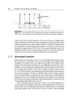
10 ~ LEAF
8 J~ TrueWave
' TrueWave RS
6
4
2 C-band L-band
"
I
0 I I I I I I I I I I
1530 ~550 1570 1590 1610
Wavelength (nm)
Figure 2.20 Dispersion profiles (slopes) of TrueWave fiber, TrueWave RS fiber, and
LEAE
As we shall see in Chapter 5, in addition to having a small value, it is important
to have a small slope (versus wavelength) for the chromatic dispersion. Having a
small slope reduces the spread in the accumulated chromatic dispersion among the
different channels in a WDM system. If the spread is small, that is, the accumulated
chromatic dispersion in different channels is close to being uniform, it may be possible
to compensate the accumulated chromatic dispersion in all the channels with a single
chromatic dispersion compensator (discussed in Chapter 5). This would be cheaper
than using a chromatic dispersion compensator for each channel. The chromatic
dispersion slopes of TrueWave fiber, TrueWave RS (reduced slope) fiber, and LEAF
(which is discussed below) are shown in Figure 2.20. Lucent's TrueWave RS fiber
has been designed to have a smaller value of the chromatic dispersion slope, about
0.05 ps/nm-km 2, compared to other NZ-DSFs, which have chromatic dispersion
slopes in the range 0.07-0.11 ps/nm-km 2.
Large Effective Area Fiber
The effect of nonlinearities can be reduced by designing a fiber with a large effective
area. We have seen that nonzero dispersion fibers have a small value of the chromatic
dispersion in the 1.55 ~m band to minimize the effects of chromatic dispersion. Un-
fortunately such fibers also have a smaller effective area. Recently, an NZ-DSF with
a large effective area~over 70 ~m2~has been developed by both Corning (LEAF)
and Lucent (TrueWave XL). This compares to about 50 ~m 2 for a typical NZ-DSF
and 85 ~m 2 for SME These fibers thus achieve a better trade-off between chromatic
dispersion and nonlinearities than normal NZ-DSFs. However, the disadvantage is
that these fibers have a larger chromatic dispersion slope, about 0.11 ps/nm-km 2
2.4 Nonlinear Effects 95
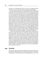
I I m
Distance from core center Distance from core center
(a) (b)
Figure 2.21 Refractive index profile of (a) normal NZ-DSF and (b) LEAE
compared to about 0.07 ps/nm-km 2 for other NZ-DSFs, and about 0.05 ps/nm-km 2
for reduced slope fiber. Another trade-off is that a large effective area also reduces
the efficiency of distributed Raman amplification (see Sections 2.4.3 and 5.8.3).
A typical refractive index profile of LEAF is shown in Figure 2.21. The core region
consists of three parts. In the innermost part, the refractive index has a triangular
variation. In the annular (middle) part, the refractive index is equal to that of the
cladding. This is surrounded by the outermost part of the core, which is an annular
region of higher refractive index. The middle part of the core, being a region of lower
refractive index, does not confine the power, and thus the power gets distributed over
a larger area. This reduces the peak power in the core and increases the effective area
of the fiber. Figure 2.22 shows the distribution of power in the cores of DSF and
LEAE
Positive and Negative Dispersion Fibers
Fibers can be designed to have either positive chromatic dispersion or negative chro-
matic dispersion in the 1.55 #m band. Typical chromatic dispersion profiles of fibers
having positive and negative chromatic dispersion in the 1.55/~m band are shown
in Figure 2.23. Positive chromatic dispersion fiber is used for terrestrial systems, and
negative chromatic dispersion fiber in submarine systems. (For chromatic dispersion
compensation, the opposite is true: negative chromatic dispersion fiber is used for ter-
restrial systems, and positive chromatic dispersion fiber for submarine systems.) Both
positive and negative chromatic dispersion cause pulse spreading, and the amount
of pulse spreading depends only on the magnitude of the chromatic dispersion, and
not on its sign (in the absence of chirping and nonlinearities). Then, why the need
for fibers with different signs of chromatic dispersion, positive for terrestrial systems
and negative for undersea links? To understand the motivation for this, we need to
understand another nonlinear phenomenon:
modulation instability.
96
PROPAGATION OF SIGNALS IN OPTICAL FIBER
1.0
0.8
r~
=~ 0.6
.3
~D
0.4
0.2
F
DSF
| , | , I | , , , I , , , | , i | , '
0 2 4 6 8 10
Distance from core center
. . . , .
12
Figure 2.22 Distribution of power in the cores of DSF and LEAE Note that the power
in the case of LEAF is distributed over a larger area. (After [Liu98].)
6 -
4
-
r~
~ 0-
0
r,~ ~2 m
~-4-
-6-
I
- J ,
Positive J ',
- dispersion ~ "~
fiby ', ,'
- -f-ff"Y'~ -',.~ ' C-band 5
_ , "!/Negative
I
, ~ dispersion
_ ,, ~ ~,
fiber
I
_ ~ ,
I i I i i i I I I I I I I
1500 1550 1600
Wavelength (nm)
Figure 2.23 Typical chromatic dispersion profiles of fibers with positive and negative
chromatic dispersion in the 1.55 #m band.
2.4 Nonlinear Effects 97
We have already seen in Section 2.3 (Figure 2.10) that pulse compression occurs
for a positively chirped pulse when the chromatic dispersion is positive (D > 0
and f32 < 0). We have also seen that SPM causes positive chirping of pulses
(Figure 2.18). When the power levels are high, the interaction between these two
phenomenamchromatic dispersion and SPM-induced chirp leads to a breakup of a
relatively broad pulse (of duration, say, 100 ps, which approximately corresponds to
10 Gb/s transmission) into a stream of short pulses (of duration a few picoseconds).
This phenomenon is referred to as
modulation instability
and leads to a significantly
increased bit error rate. Modulation instability occurs only in positive chromatic
dispersion fiber and thus can be avoided by the use of negative chromatic dispersion
fiber. Its effects in positive chromatic dispersion fiber can be minimized by using
lower power levels. (In the next section, we will see that due to the same interaction
between SPM and chromatic dispersion that causes modulation instability, a family
of narrow, high-power pulses with specific shapes, called solitions, can propagate
without pulse broadening.)
WDM systems cannot operate around the zero-dispersion wavelength of the fiber
due to the severity of four-wave mixing. For positive chromatic dispersion fiber, the
dispersion zero lies below the 1.55 #m band, and not in the L-band. Hence, systems
using positive chromatic dispersion fiber can be upgraded to use the L-band (see
Figure 2.7). This upgradability is an important feature for terrestrial systems. Thus,
positive chromatic dispersion fiber is preferred for terrestrial systems, and the power
levels are controlled so that modulation instability is not significant. For undersea
links, however, the use of higher power levels is very important due to the very long
link lengths. These links are not capable of being upgraded anyway since they are
buried on the ocean floor so the use of the L-band in these fibers at a later date is
not possible. Hence negative chromatic dispersion fiber is used for undersea links.
Since negative chromatic dispersion fiber is used for undersea links, the chromatic
dispersion can be compensated using standard single-mode fiber (SMF), which has
positive chromatic dispersion; that is, alternating lengths of negative chromatic dis-
persion fiber and (positive chromatic dispersion) SMF can be used to keep the total
chromatic dispersion low. This is preferable to using dispersion compensating fibers
since they are more susceptible to nonlinear effects because of their lower effective
areas.
Note that all the fibers we have considered have positive chromatic dispersion
slope; that is, the chromatic dispersion increases with increasing wavelength. This is
mainly because the material dispersion slope of silica is positive and usually dom-
inates the negative chromatic dispersion slope of waveguide dispersion (see Fig-
ure 2.12). Negative chromatic dispersion slope fiber is useful in chromatic dispersion
slope compensation, a topic that we discuss in Section 5.7.3. While it is possible
to build a negative chromatic dispersion fiber (in the
1.55
#m band) with negative
98
PROPAGATION OF SIGNALS IN OPTICAL FIBER
Negative dispersion,
__ positive slope fiber
E 0.10 - - LEAF-, TrueWave XL- O
=' Submarine LS- 0
~ 0.05 - - TrueWave RS- O
0.00 -
. Negative dispersion,
r~
= .'-7 negative slope fiber
r~
-0.25
-0.30
,,,
Positive dispersion,
positive slope fiber
0 LEAF+/TeraLight
O "~ o C-SMF
O
TrueWave RS+
0
Dispersion compensating
fiber
I I I t- ' '
i i
I
dispersion
U/v' ne~tive~l~
I I I I I I I
-100 -10 -5, 0 5 10 15 20
Dispersion (ps/km-nm) in C-band (1550 nm)
Figure
2.24 Chromatic dispersion in the C-band, and the chromatic dispersion slope,
for various fiber types.
slope, it is considered difficult to design a positive chromatic dispersion fiber with
negative slope.
In Figure 2.24, we summarize the chromatic dispersion in the C-band, and the
chromatic dispersion slope, for all the fibers we have discussed.
2.5
Solitons
Solitons are narrow pulses with high peak powers and special shapes. The most
commonly used soliton pulses are called
fundamental solitons.
The shape of these
pulses is shown in Figure 2.25. As we have seen in Section 2.3, most pulses undergo
broadening (spreading in time) due to group velocity dispersion when propagating
through optical fiber. However, the soliton pulses take advantage of nonlinear effects
in silica, specifically self-phase modulation discussed in Section 2.4.5, to overcome
the pulse-broadening effects of group velocity dispersion. Thus these pulses can
propagate for long distances with no change in shape.
We mentioned in Section 2.3, and discuss in greater detail in Appendix E, that
a pulse propagates with the group velocity 1/ill along the fiber and that, in general,
because of the effects of group velocity dispersion, the pulse progressively broadens
as it propagates. If f12 = 0, all pulse shapes propagate without broadening, but if
f12 -~ 0, is there any pulse shape that propagates without broadening? The key to
2.5 Solitons
99
(a)
(b)
Figure
2.25 (a) A fundamental soliton pulse and (b) its envelope.
the answer lies in the one exception to this pulse-broadening effect that we already
encountered in Section 2.3, namely, that if the chirp parameter of the pulse has the
right sign (opposite to that of/32), the pulse initially undergoes compression. But we
have seen that even in this case (Problem 2.11), the pulse subsequently broadens. This
happens in all cases where the chirp is
independent
of the pulse envelope. However,
when the chirp is induced by SPM, the degree of chirp depends on the pulse envelope.
If the relative effects of SPM and GVD are controlled just right, and the appropriate
pulse shape is chosen, the pulse compression effect undergone by chirped pulses
can exactly offset the pulse-broadening effect of dispersion. The pulse shapes for
which this balance between pulse compression and broadening occurs so that the
pulse either undergoes no change in shape or undergoes periodic changes in shape
only are called
solitons.
The family of pulses that undergo no change in shape are
called
fundamental solitons,
and those that undergo periodic changes in shape are