Optical Networks: A Practical Perspective - Part 16 pptx
Bạn đang xem bản rút gọn của tài liệu. Xem và tải ngay bản đầy đủ của tài liệu tại đây (640.09 KB, 10 trang )
120
COMPONENTS
Consider the grating shown in Figure 3.9(a). Multiple narrow slits are spaced
equally apart on a plane, called the
grating plane.
The spacing between two adjacent
slits is called the
pitch
of the grating. Light incident from a source on one side
of the grating is transmitted through these slits. Since each slit is narrow, by the
phenomenon known as
diffraction,
the light transmitted through each slit spreads
out in all directions. Thus each slit acts as a secondary source of light. Consider
some other plane parallel to the grating plane at which the transmitted light from
all the slits interferes. We will call this plane the
imaging plane.
Consider any point
on this imaging plane. For wavelengths for which the individual interfering waves
at this point are in phase, we have constructive interference and an enhancement
of the light intensity at these wavelengths. For a large number of slits, which is the
case usually encountered in practice, the interference is not constructive at other
wavelengths, and there is little light intensity at this point from these wavelengths.
Since different wavelengths interfere constructively at different points on the imaging
plane, the grating effectively separates a WDM signal spatially into its constituent
wavelengths. In a fiber optic system, optical fibers could be placed at different imaging
points to collect light at the different wavelengths.
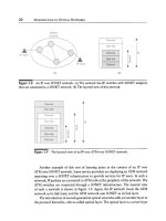
Note that if there were no diffraction, we would simply have light transmitted
or reflected along the directed dotted lines in Figure 3.9(a) and (b). Thus the phe-
nomenon of diffraction is key to the operation of these devices, and for this reason
they are called
diffraction gratings.
Since multiple transmissions occur in the grating
of Figure 3.9(a), this grating is called a
transmission grating.
If the transmission slits
are replaced by narrow reflecting surfaces, with the rest of the grating surface being
nonreflecting, we get the
reflection grating
of Figure 3.9(b). The principle of opera-
tion of this device is exactly analogous to that of the transmission grating. A majority
of the gratings used in practice are reflection gratings since they are somewhat easier
to fabricate. In addition to the plane geometry we have considered, gratings are
fabricated in a concave geometry. In this case, the slits (for a transmission grating)
are located on the arc of a circle. In many applications, a concave geometry leads to
fewer auxiliary parts like lenses and mirrors needed to construct the overall device,
say, a WDM demultiplexer, and is thus preferred.
The Stimax grating [LL84] is a reflection grating that is integrated with a concave
mirror and the input and output fibers. Its characteristics are described in Table 3.1,
and it has been used in commercially available WDM transmission systems. However,
it is a bulk device that cannot be easily fabricated and is therefore relatively expensive.
Attempts have been made to realize similar gratings in optical waveguide technology,
but these devices are yet to achieve loss, PDL, and isolation comparable to the bulk
version.
3.3 Multiplexers and Filters
121
Principle of Operation
To understand quantitatively the principle of operation of a (transmission) grating,
consider the light transmitted through adjacent slits as shown in Figure 3.10. The
distance between adjacent slits the
pitch
of the gratingmis denoted by a. We assume
that the light source is far enough away from the grating plane compared to a so that
the light can be assumed to be incident at the same angle
0i
to the plane of the grating
at each slit. We consider the light rays diffracted at an angle 0d from the grating plane.
The imaging plane, like the source, is assumed to be far away from the grating plane
compared to the grating pitch. We also assume that the slits are small compared
to the wavelength so that the phase change across a slit is negligible. Under these
assumptions, it can be shown (Problem 3.4) that the path length difference between
the rays traversing through adjacent slits is the difference in lengths between the
line segments
AB
and
CD
and is given approximately by
a[sin(Oi) -
sin(Od)]. Thus
constructive interference at a wavelength ~ occurs at the imaging plane among the
rays diffracted at angle Od if the following
grating equation
is satisfied:
a[sin(Oi) -
sin(Od)] = m,k
(3.9)
for some integer m, called the
order
of the grating. The grating effects the separation
of the individual wavelengths in a WDM signal since the grating equation is satisfied
at different points in the imaging plane for different wavelengths. This is illustrated
in Figure 3.9, where different wavelengths are shown being diffracted at the angles
at which the grating equation is satisfied for that wavelength. For example, 0dl is the
angle at which the grating equation is satisfied for )~1.
Note that the energy at a single wavelength is distributed over all the discrete
angles that satisfy the grating equation (3.9) at this wavelength. When the grating is
used as a demultiplexer in a WDM system, light is collected from only one of these
angles, and the remaining energy in the other orders is lost. In fact, most of the energy
will be concentrated in the zeroth-order (m = 0) interference maximum, which occurs
at
0i = Od
for all wavelengths. The light energy in this zeroth-order interference
maximum is wasted since the wavelengths are not separated. Thus gratings must
be designed so that the light energy is maximum at one of the other interference
maxima. This is done using a technique called
blazing
[KF86, p. 386].
Figure 3.11 shows a blazed reflection grating with blaze angle ~. In such a grating,
the reflecting slits are inclined at an angle ~ to the grating plane. This has the effect of
maximizing the light energy in the interference maximum whose order corresponds
to the blazing angle. The grating equation for such a blazed grating can be derived
as before; see Problem 3.5.
122
COMPONENTS
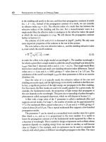
Figure 3.10 Principle of operation of a transmission grating. The reflection grating
works in an analogous manner. The path length difference between rays diffracted at
angle
Oa
from adjacent slits is
AB - CD = a[sin(Oi) -
sin(0d)].
Figure 3.11 A blazed grating with blaze angle o~. The energy in the interference maxi-
mum corresponding to the blaze angle is maximized.
3.3.2
Diffraction Pattern
So far, we have only considered the position of the diffraction maxima in the diffrac-
tion pattern. Often, we are also interested in the distribution of the intensity in the
diffraction maxima. We can derive the distribution of the intensity by relaxing the as-
sumption that the slits are much smaller than a wavelength, so that the phase change
across a slit can no longer be neglected. Consider a slit of length w stretching from
y = -w/2
to y =
w/2.
By reasoning along the same lines as we did in Figure 3.10,
the light diffracted from position y at angle 0 from this slit has a relative phase shift
of 4~(y) = (2try sin0)/)~ compared to the light diffracted from y = 0. Thus, at the
3.3 Multiplexers and Filters
123
imaging plane, the amplitude A (0) at angle 0 is given by
A(O)
A(0)
1
fw/2
=
exp (i4)(y)) dy
w a-w~2
1
fw/2
= exp(i2rr(sinO)y/Z) dy
W ,J-w~2
sin (zrw sin 0/Z)
re w sin 0/Z
(3.10)
Observe that the amplitude distribution at the imaging plane is the Fourier transform
of the rectangular slit. This result holds for a general diffracting aperture, and not
just a rectangular slit. For this more general case, if the diffracting aperture or slit is
described by f(y), the amplitude distribution of the diffraction pattern is given by
F
A(O)- A(O) f(y)exp(2rci(sinO)y/Z)dy.
oo
(3.11)
The intensity distribution is given by IA(0)i 2. Here, we assume f(y) is normalized so
that f-~cx~ f(Y) dy - 1. For a rectangular slit, f(y) - 1/w for ]y] < w/2 and f(y) - O,
otherwise, and the diffraction pattern is given by (3.10). For a pair of narrow slits
spaced distance d apart,
f (y) 0.5(6(y - d/2) 4- 3(y 4- d/2))
and
A(O) A(O) cos (Tr(sin O)Z/d) .
The more general problem of N narrow slits is discussed in Problem 3.6.
3.3.3
Bragg Gratings
Bragg gratings are widely used in fiber optic communication systems. In general,
any periodic perturbation in the propagating medium serves as a Bragg grating. This
perturbation is usually a periodic variation of the refractive index of the medium.
We will see in Section 3.5.1 that lasers use Bragg gratings to achieve single frequency
operation. In this case, the Bragg gratings are "written" in waveguides. Bragg gratings
written in fiber can be used to make a variety of devices such as filters, add/drop
multiplexers, and dispersion compensators. We will see later that the Bragg grating
principle also underlies the operation of the acousto-optic tunable filter. In this case,
the Bragg grating is formed by the propagation of an acoustic wave in the medium.
124 COMPONENTS
Principle of Operation
Consider two waves propagating in opposite directions with propagation constants
/~0 and/~1. Energy is coupled from one wave to the other if they satisfy the Bragg
phase-matching
condition
27r
I~o - ~1 =
A'
where A is the period of the grating. In a Bragg grating, energy from the forward
propagating mode of a wave at the right wavelength is coupled into a backward
propagating mode. Consider a light wave with propagation constant/51 propagating
from left to right. The energy from this wave is coupled onto a scattered wave
traveling in the opposite direction at the same wavelength provided
2Jr
I~0 - (-t~0)l = 2t~0 =
~.
A
Letting/~0 = 27rneff/)~0, ~.0 being the wavelength of the incident wave and neff the
effective refractive index of the waveguide or fiber, the wave is reflected provided
~.0 = 2neffA.
This wavelength )~0 is called the Bragg wavelength. In practice, the reflection effi-
ciency decreases as the wavelength of the incident wave is detuned from the Bragg
wavelength; this is plotted in Figure 3.12(a). Thus if several wavelengths are trans-
mitted into a fiber Bragg grating, the Bragg wavelength is reflected while the other
wavelengths are transmitted.
The operation of the Bragg grating can be understood by reference to Figure 3.13,
which shows a periodic variation in refractive index. The incident wave is reflected
from each period of the grating. These reflections add in phase when the path length
in wavelength ~.0 each period is equal to half the incident wavelength )~0. This is
equivalent to
neffA = )~0/2,
which is the Bragg condition.
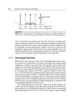
The reflection spectrum shown in Figure 3.12(a) is for a grating with a uniform
refractive index pattern change across its length. In order to eliminate the undesirable
side lobes, it is possible to obtain an
apodized
grating, where the refractive index
change is made smaller toward the edges of the grating. (The term
apodized
means
"to cut off the feet.") The reflection spectrum of an apodized grating is shown
in Figure 3.12(b). Note that, for the apodized grating, the side lobes have been
drastically reduced but at the expense of increasing the main lobe width.
The index distribution across the length of a Bragg grating is analogous to the
grating aperture discussed in Section 3.3.2, and the reflection spectrum is obtained
as the Fourier transform of the index distribution. The side lobes in the case of a
uniform refractive index profile arise due to the abrupt start and end of the grating,
3.3 Multiplexers and Filters 125
0
~ -10
-20
~ -30
|
-40 _ -2 0
A,k/A
(n)
0
i , , ,
-40 4
-4 -2 0 2
A)~/A
(b)
-10
2
r~
~ -20
0
-30
Figure 3.12 Reflection spectra of Bragg gratings with (a) uniform index profile and
(b) apodized index profile. A is a measure of the bandwidth of the grating and is the
wavelength separation between the peak wavelength and the first reflection minimum, in
the uniform index profile case. A is inversely proportional to the length of the grating.
AZ is the detuning from the phase-matching wavelength.
126 COMrONENTS
I
Figure 3.13 Principle of operation of a Bragg grating.
3.3.4
which result in a sinc(.) behavior for the side lobes. Apodization can be achieved by
gradually starting and ending the grating. This technique is similar to pulse shaping
used in digital communication systems to reduce the side lobes in the transmitted
spectrum of the signal.
The bandwidth of the grating, which can be measured, for example, by the width
of the main lobe, is inversely proportional to the length of the grating. Typically, the
grating is a few millimeters long in order to achieve a bandwidth of I nm.
Fiber Gratings
Fiber gratings are attractive devices that can be used for a variety of applications,
including filtering, add/drop functions, and compensating for accumulated dispersion
in the system. Being all-fiber devices, their main advantages are their low loss, ease of
coupling (with other fibers), polarization insensitivity, low temperature coefficient,
and simple packaging. As a result, they can be extremely low-cost devices.
Gratings are written in fibers by making use of the
photosensitivity
of certain
types of optical fibers. A conventional silica fiber doped with germanium becomes
extremely photosensitive. Exposing this fiber to ultraviolet (UV) light causes changes
in the refractive index within the fiber core. A grating can be written in such a fiber
by exposing its core to two interfering UV beams. This causes the radiation intensity
to vary periodically along the length of the fiber. Where the intensity is high, the
refractive index is increased; where it is low, the refractive index is unchanged. The
change in refractive index needed to obtain gratings is quite small around 10 -4.
Other techniques, such as
phase masks,
can also be used to produce gratings. A phase
mask is a diffractive optical element. When it is illuminated by a light beam, it splits
the beams into different diffractive orders, which then interfere with one another to
write the grating into the fiber.
Fiber gratings are classified as either
short-period
or
long-period
gratings, based
on the period of the grating. Short-period gratings are also called Bragg gratings and
have periods that are comparable to the wavelength, typically around 0.5/~m. We
3.3 Multiplexers and Filters 127
discussed the behavior of Bragg gratings in Section 3.3.3. Long-period gratings, on
the other hand, have periods that are much greater than the wavelength, ranging
from a few hundred micrometers to a few millimeters.
Fiber Bragg Gratings
Fiber Bragg gratings can be fabricated with extremely low loss (0.1 dB), high wave-
length accuracy (• 0.05 nm is easily achieved), high adjacent channel crosstalk
suppression (40 dB), as well as flat tops.
The temperature coefficient of a fiber Bragg grating is typically 1.25 x 10 -2 nm/~
due to the variation in fiber length with temperature. However, it is possible to
compensate for this change by packaging the grating with a material that has a
negative thermal expansion coefficient. These passively temperature-compensated
gratings have temperature coefficients of around 0.07 • 10 -2 nm/~ This implies
a very small 0.07 nm center wavelength shift over an operating temperature range
of 100~ which means that they can be operated without any active temperature
control.
These properties of fiber Bragg gratings make them very useful devices for sys-
tem applications. Fiber Bragg gratings are finding a variety of uses in WDM systems,
ranging from filters and optical add/drop elements to dispersion compensators. A
simple optical drop element based on fiber Bragg gratings is shown in Figure 3.14(a).
It consists of a three-port circulator with a fiber Bragg grating. The circulator trans-
mits light coming in on port 1 out on port 2 and transmits light coming in on port
2 out on port 3. In this case, the grating reflects the desired wavelength )~2, which is
then dropped at port 3. The remaining three wavelengths are passed through. It is
possible to implement an add/drop function along the same lines, by introducing a
coupler to add the same wavelength that was dropped, as shown in Figure 3.14(b).
Many variations of this simple add/drop element can be realized by using gratings
in combination with couplers and circulators. A major concern in these designs is
that the reflection of these gratings is not perfect, and as a result, some power at the
selected wavelength leaks through the grating. This can cause undesirable crosstalk,
and we will study this effect in Chapter 5.
Fiber Bragg gratings can also be used to compensate for dispersion accumulated
along the link. We will study this application in Chapter 5 in the context of dispersion
compensation.
Long-Period Fiber Gratings
Long-period fiber gratings are fabricated in the same manner as fiber Bragg gratings
and are used today primarily as filters inside erbium-doped fiber amplifiers to com-
pensate for their nonflat gain spectrum. As we will see, these devices serve as very
128 COMVONENTS
Figure 3.14 Optical add/drop elements based on fiber Bragg gratings. (a) A drop ele-
ment. (b) A combined add/drop element.
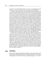
efficient band rejection filters and can be tailored to provide almost exact equaliza-
tion of the erbium gain spectrum. Figure 3.15 shows the transmission spectrum of
such a grating. These gratings retain all the attractive properties of fiber gratings and
are expected to become widely used for several filtering applications.
Principle of Operation
These gratings operate on somewhat different principles than Bragg gratings. In
fiber Bragg gratings, energy from the forward propagating mode in the fiber core at
the right wavelength is coupled into a backward propagating mode. In long-period
gratings, energy is coupled from the forward propagating mode in the fiber core
onto other forward propagating modes in the cladding. These cladding modes are
extremely lossy, and their energy decays rapidly as they propagate along the fiber,
due to losses at the cladding-air interface and due to microbends in the fiber. There
are many cladding modes, and coupling occurs between a core mode at a given
3.3 Multiplexers and Filters
129
-1
~, -2
= -3
0
. , ~
r.~
r~
., ,
E -4
r~
-5
-6
, , , , I , 9 9 9 | 9 9 | , I | , , , I , | , | I
1.53 1.54 1.55 1.56 1.57 1.58
Wavelength, )~ (~m)
Figure
3.15 Transmission spectrum of a long-period fiber Bragg grating used as a gain
equalizer for erbium-doped fiber amplifiers. (After [Ven96a].)
wavelength and a cladding mode depending on the pitch of the grating A, as follows:
if/3 denotes the propagation constant of the mode in the core (assuming a single-mode
fiber) and flc~ that of the pth-order cladding mode, then the phase-matching condition
dictates that
2Jr
In general, the difference in propagation constants between the core mode and any
one of the cladding modes is quite small, leading to a fairly large value of A in order
for coupling to occur. This value is usually a few hundred micrometers. (Note that
in Bragg gratings the difference in propagation constants between the forward and
backward propagating modes is quite large, leading to a small value for A, typically
P denote the effective refractive indices of the core and
around 0.5 #m.) If neff and ne~
pth-order cladding modes, then the wavelength at which energy is coupled from the
core mode to the cladding mode can be obtained as
,k A(neff P
where we have used the relation fl =
27rneff/,k.
Therefore, once we know the effective indices of the core and cladding modes,
we can design the grating with a suitable value of A so as to cause coupling
of energy out of a desired wavelength band. This causes the grating to act as
a wavelength-dependent loss element. Methods for calculating the propagation