Optical Networks: A Practical Perspective - Part 21 pptx
Bạn đang xem bản rút gọn của tài liệu. Xem và tải ngay bản đầy đủ của tài liệu tại đây (741 KB, 10 trang )
170
COMPONENTS
In the corrugated section of the cavity, the incident wave undergoes a series
of reflections. The contributions of each of these reflected waves to the resulting
transmitted wave from the cavity add in phase if the period of the corrugation is
an integral multiple of half the wavelength in the cavity. The reasoning for this
condition is the same as that used for the Fabry-Perot cavity. This condition is
called the Bragg condition and was discussed in Section 3.3.3. The Bragg condition
will be satisfied for a number of wavelengths, but the strongest transmitted wave
occurs for the wavelength for which the corrugation period is
equal
to half the
wavelength, rather than some other integer multiple of it. Thus this wavelength gets
preferentially amplified at the expense of the other wavelengths. By suitable design
of the device, this effect can be used to suppress all other longitudinal modes so that
the laser oscillates in a single-longitudinal mode whose wavelength is equal to twice
the corrugation period. By varying the corrugation period at the time of fabrication,
different operating wavelengths can be obtained.
Any laser that uses a corrugated waveguide to achieve single-longitudinal mode
operation can be termed a distributed-feedback laser. However, the acronym
DFB
laser
is used only when the corrugation occurs within the gain region of the cavity,
as shown in Figure 3.44(a). When the corrugation is outside the gain region, as in
Figure 3.44(b), the laser is called a
distributed Bragg reflector
(DBR) laser. The main
advantage of DBR lasers is that the gain region is decoupled from the wavelength
selection region. Thus it is possible to control both regions independently. For exam-
ple, by changing the refractive index of the wavelength selection region, the laser can
be tuned to a different wavelength without affecting its other operating parameters.
Indeed, this is how many of the tunable lasers that we will study in Section 3.5.3 are
realized.
DFB lasers are inherently more complex to fabricate than FP lasers and thus
relatively more expensive. However, DFB lasers are required in almost all high-speed
transmission systems today. FP lasers are used for shorter-distance data communica-
tion applications.
Reflections into a DFB laser cause its wavelength and power to fluctuate and are
prevented by packaging the laser with an isolator in front of it. The laser is also
usually packaged with a thermoelectric (TE) cooler and a photodetector attached to
its rear facet. The TE cooler is necessary to maintain the laser at a constant operating
temperature to prevent its wavelength from drifting. The temperature sensitivity of
a semiconductor DFB laser operating in the 1.55 #m wavelength region is about
0.1 nm/~ The photodetector monitors the optical power leaking out of the rear
facet, which is proportional to the optical power coming out of the laser.
The packaging of a DFB laser contributes a significant fraction of the overall cost
of the device. For WDM systems, it is very useful to package multiple DFB lasers
at different wavelengths inside a single package. This device can then serve as a
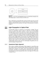
3.5 Transmitters 171
Figure 3.45 The structure of an external cavity laser.
multiwavelength light source or, alternatively, as a tunable laser (only one of the lasers
in the array is turned on, depending on the desired wavelength). These lasers can all be
grown on a single substrate in the form of an array. Four- and eight-wavelength laser
arrays have been fabricated in research laboratories, but have not quite progressed
to volume manufacturing. The primary reason for this is the relatively low yield of
the array as a whole. If one of the lasers doesn't meet specifications, the entire array
will have to be discarded.
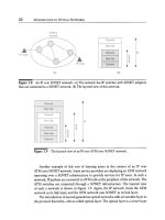
External Cavity Lasers
Suppression of oscillation at more than one longitudinal mode can also be achieved
by using another cavitymcalled an
external cavitymfollowing
the primary cavity
where gain occurs. This is illustrated in Figure 3.45. Just as the primary cavity has
resonant wavelengths, so does the external cavity. This effect can be achieved, for
example, by using reflecting facets for the external cavity as well. The net result
of having an external cavity is that the laser is capable of oscillating only at those
wavelengths that are resonant wavelengths of
both
the primary and external cavity.
By suitable design of the two cavities, it can be ensured that only one wavelength
in the gain bandwidth of the primary cavity satisfies this condition. Thus the laser
oscillation can be confined to a single-longitudinal mode.
Instead of another Fabry-Perot cavity, as shown in Figure 3.45, we can use a
diffraction grating (see Section 3.3.1) in the external cavity, as shown in Figure 3.46.
Such a laser is called a
grating external cavity
laser. In this case, the facet of the
gain cavity facing the grating is given an antireflection coating. The wavelengths
reflected by the diffraction grating back to the gain cavity are determined by the
pitch of the grating (see Section 3.3.1) and its tilt angle (see Figure 3.46) with respect
to the gain cavity. An external cavity laser, in general, uses a
wavelength-selective
mirror
instead of a wavelength-flat mirror. (A highly polished and/or metal-coated
facet used in conventional lasers acts as a wavelength-flat mirror.) The reflectiv-
ity of a wavelength-selective mirror is a function of the wavelength. Thus only
certain wavelengths experience high reflectivities and are capable of lasing. If the
172
COMPONENTS
Figure 3.46 The structure of a grating external cavity laser. By rotating the grating, we
can tune the wavelength of the laser.
wavelength-selective mirror is chosen suitably, only one such wavelength will occur
within the gain bandwidth, and we will have a single-mode laser.
Several of the filters discussed in Section 3.3 can be used as wavelength-selective
mirrors in external cavity lasers. We have already seen the use of the diffraction
grating (Section 3.3.1) and Fabry-Perot filter (Section 3.3.5) in external cavity lasers.
These laser structures are used today primarily in optical test instruments and are
not amenable to low-cost volume production as SLM light sources for transmission
systems. One version of the external cavity laser, though, appears to be particularly
promising for this purpose. This device uses a fiber Bragg grating in front of a
conventional FP laser with its front facet AR coated. This device then acts as an
SLM DBR laser. It can be fabricated at relatively low cost compared to DFB lasers
and is inherently more temperature stable in wavelength due to the low temperature
coefficient of the fiber grating.
One disadvantage of external cavity lasers is that they cannot be modulated
directly at high speeds. This is related to the fact that the cavity length is large.
Vertical Cavity Surface-Emitting Lasers
In this section, we will study another class of lasers that achieve single-longitudinal
mode operation in a slightly different manner. As we saw in Figure 3.43, the frequency
spacing between the modes of an MLM laser is
c/2nl,
where l is the length of the
cavity and n is its refractive index. If we were to make the length of the cavity
sufficiently small, the mode spacing increases such that only one longitudinal mode
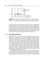
occurs within the gain bandwidth of the laser. It turns out that making a very
thin active layer is much easier if the active layer is deposited on a semiconductor
substrate, as illustrated in Figure 3.47. This leads to a vertical cavity with the mirrors
3.5 Transmitters
173
Figure
3.47 The structure of a VCSEL.
being formed on the top and bottom surfaces of the semiconductor wafer. The laser
output is also taken from one of these (usually top) surfaces. For these reasons, such
lasers are called
vertical cavity surface-emitting lasers
(VCSELs). The other lasers
that we have been discussing hitherto can thus be referred to as
edge-emitting lasers.
Since the gain region has a very short length, very high mirror reflectivities are
required in order for laser oscillation to occur. Such high mirror reflectivities are
difficult to obtain with metallic surfaces. A stack of alternating low- and high-index
dielectrics serves as a highly reflective, though wavelength-selective, mirror. The
reflectivity of such a mirror is discussed in Problem 3.13. Such dielectric mirrors can
be deposited at the time of fabrication of the laser.
One problem with VCSELs is the large ohmic resistance encountered by the
injected current. This leads to considerable heating of the device and the need for
efficient thermal cooling. Many of the dielectric materials used to make the mirrors
have low thermal conductivity. So the use of such dielectric mirrors makes room
temperature operation of VCSELs difficult to achieve since the heat generated by the
device cannot be dissipated easily. For this reason, for several years after they were
first demonstrated in 1979, VCSELs were not capable of operating at room temper-
ature. However, significant research effort has been expended on new materials and
techniques, and as of this writing, VCSELs operating at 1.3 #m at room temperature
have been demonstrated [Har00].
The advantages of VCSELs, compared to edge-emitting lasers, include simpler
and more efficient fiber coupling, easier packaging and testing, and their ability to
be integrated into multiwavelength arrays. As of this writing, VCSELs operating at
0.85 #m are commercially available and used for low-cost, short-distance multimode
fiber interconnections. For single-mode fiber applications, 1.3 #m VCSELs are now
becoming commercially available. There is work under way to produce 1.5 #m lasers
as well. We will see one example in Section 3.5.3.
174
COMPONENTS
Figure
3.48 A two-dimensional array of vertical cavity surface-emitting lasers.
In a WDM system, many wavelengths are transmitted simultaneously over each
link. Usually, this requires a separate laser for each wavelength. The cost of the
transmitters can be significantly reduced if all the lasers can be integrated on a single
substrate. This is the main motivation for the development of arrayed lasers such
as the DFB laser arrays that we discussed earlier. Moreover, an arrayed laser can
be used as a tunable laser simply by turning on only the one required laser in the
array. The use of surface-emitting lasers enables us to fabricate a two-dimensional
array of lasers, as shown in Figure 3.48. Much higher array packing densities can be
achieved using surface-emitting lasers than edge-emitting ones because of this added
dimension. However, it is harder to couple light from the lasers in this array onto
optical fiber since multiplexers that work conveniently with this two-dimensional
geometry are not readily available. These arrayed lasers have the same yield problem
as other arrayed laser structures; if one of the lasers doesn't meet specifications, the
entire array will have to be discarded.
Mode-Locked Lasers
Mode-locked lasers are used to generate narrow optical pulses that are needed for the
high-speed TDM systems that we will study in Chapter 12. Consider a Fabry-Perot
laser that oscillates in N longitudinal modes, which are adjacent to each other. This
means that if the wavelengths of the modes are )~0,
)~1 ~.N-1,
the cavity length l
satisfies
I = (k
+i)Xi/2,
i 0,
1 N- 1, for some integer k. From this condition, it
can be shown (see Problem 3.7) that the corresponding frequencies
fo, fl fN-1
of these modes must satisfy
fi = fo + i Af,
i = 0, 1 N - 1. The oscillation at
frequency fi is of the form
ai
cos(27rf/t + ~i), where
ai
is the amplitude and
~)i
the
phase of mode i. (Strictly speaking, this is the distribution in time of the electric field
3.5 Transmitters 175
iVVVlV'V VVVVV V tV V'V V II /
"'~ 2nl/c ~
(a)
VVVV VV' VVVI V v
Time "'-
~w V, vv,v~~~wv~
9 "~ 2nl/c "-
(b)
,A.A_A A,^ A_A.A,I
Time
I,A.A.A A,
vV v V vv w v
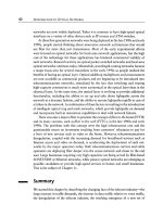
Figure
3.49 Output oscillation of a laser oscillating simultaneously in 10 longitudinal
modes. (a) The phases of the modes are chosen at random. (b) All the phases are equal
to each other; such a laser is said to be mode locked.
associated with the longitudinal mode.) Thus the total laser output oscillation takes
the form
N-1
Z ai
cos(27rfi t +
4)i).
i=0
This expression is plotted in Figure 3.49 for N - 10, for different sets of values of
the 4~i. In Figure 3.49(a), the 4~i are chosen at random, and in Figure 3.49(b), they
are chosen to be equal to each other. All the
ai
are chosen to be equal in both cases,
176
COMPONENTS
3.5.2
and the frequency f0 has been diminished from its typical value for the purpose of
illustration.
From Figure 3.49(a), we observe that the output amplitude of an MLM laser
varies rapidly with time when it is not mode locked. We have also seen in Fig-
ure 3.43(a) that the frequency spacing between adjacent longitudinal modes is
c/2nl.
If n = 3 and 1 = 200 #m, which are typical values for semiconductor lasers, this
frequency spacing is 250 GHz. Thus these amplitude fluctuations occur extremely
rapidly (at a time scale on the order of a few picoseconds) and pose no problems for
on-off modulation even at bit rates of a few tens of gigabits per second.
We see from Figure 3.49(b) that when the 4~i are chosen to be equal to each
other, the output oscillation of the laser takes the form of a periodic train of narrow
pulses. A laser operating in this manner is called a
mode-locked laser
and is the most
common means of generating narrow optical pulses.
The time interval between two pulses of a mode-locked laser is
2nl/c,
as indicated
in Figure 3.49(b). For a typical semiconductor laser, as we have seen earlier, this
corresponds to a few picoseconds. For modulation in the 1-10 GHz range, the
interpulse interval should be in the 0.1-1 ns range. Cavity lengths, I, of the order
of 1-10 cm (assuming n = 1.5) are required in order to realize mode-locked lasers
with interpulse intervals in this range. These large cavity lengths are easily obtained
using fiber lasers, which require the length anyway to obtain sufficient gain to induce
lasing.
The most common means of achieving mode lock is by modulating the gain
of the laser cavity. Either amplitude or frequency modulation can be used. Mode
locking using amplitude modulation is illustrated in Figure 3.50. The gain of the
cavity is modulated with a period equal to the interpulse interval, namely,
2nl/c.
The amplitude of this modulation is chosen such that the average gain is insufficient
for any single mode to oscillate. However, if a large number of modes are in phase,
there can be a sufficient buildup in the energy inside the cavity for laser oscillation
to occur at the instants of high gain, as illustrated in Figure 3.50.
Gain modulation of the fiber laser can be achieved by introducing an external
modulator inside the cavity.
Light-Emitting Diodes
Lasers are expensive devices and are not affordable for many applications where the
data rates are low and distances are short. This is the case in many data communi-
cations applications (see Chapter 6) and in some access networks (Chapter 11). In
such cases,
light-emitting diodes
(LEDs) provide a cheaper alternative.
An LED is a forward-biased pn-junction in which the recombination of the
injected minority carriers (electrons in the p-type region and holes in the n-type
Medium
gain
Laser output
intensity
3.5 Transmitters
177
-" 2//c
~t n
Time
Figure 3.50 Illustration of mode locking by amplitude modulation of the cavity gain.
region) by the spontaneous emission process produces light. (Unwanted nonradiative
recombination is also possible and is an important factor affecting the performance of
LEDs.) Because spontaneous emission occurs within the entire bandwidth of the gain
medium (corresponding to all energy differences between the valence and conduction
bands for an LED), the light output of an LED has a broad spectrum, unlike that
of a laser. We can crudely think of an LED as a laser with facets that are not very
reflective. Increasing the pump current simply increases the spontaneous emission,
and there is no chance to build up stimulated emission due to the poor reflectivity
of the facets. For this reason, LEDs are also not capable of producing high-output
powers like lasers, and typical output powers are on the order of-20 dBm. They
cannot be directly modulated (see Section 3.5.4) at data rates higher than a few
hundred megabits per second.
In some low-speed, low-budget applications, there is a requirement for a source
with a narrow spectral width. DFB lasers provide narrow spectral widths but may be
too expensive for these applications. In such cases,
LED slicing
provides a cheaper
alternative. An LED slice is the output of a narrow passband optical filter placed in
front of the LED. The optical filter selects a portion of the LED's output. Different
178
COMPONENTS
filters can be used to select (almost) nonoverlapping spectral slices of the LED output.
Thus one LED can be shared by a number of users. We will see an application for
this technique in Chapter 11.
3.5.3
Tunable Lasers
Tunable lasers are highly desirable components for WDM networks for several rea-
sons. Fixed-wavelength DFB lasers work very well for today's applications. However,
each wavelength requires a different, unique laser. This implies that in order to sup-
ply a 100-channel WDM system, we need to stock 100 different laser types. The
inventory and sparing issues associated with this are expensive and affect everybody
from laser manufacturers to network operators. Laser manufacturers need to set
up multiple production and test lines for each laser wavelength (or time-share the
same production and test line but change the settings each time a different laser is
made). Equipment suppliers need to stock these different lasers and keep inventories
and spares for each wavelength. Finally, network operators need to stockpile spare
wavelengths in the event transmitters fail in the field and need to be replaced. Having
a tunable laser alleviates this problem dramatically.
Tunable lasers are also one of the key enablers of reconfigurable optical networks.
They provide the flexibility to choose the transmit wavelength at the source of a
lightpath. For instance, if we wanted to have a total of, say, four lightpaths starting
at a node, we would equip that node with four tunable lasers. This would allow
us to choose the four transmit wavelengths in an arbitrary manner. In contrast, if
we were to use fixed-wavelength lasers, either we would have to preequip the node
with a large number of lasers to cover all the possible wavelengths, or we would
have to manually equip the appropriate wavelength as needed. We will see more of
this application in Chapter 7. The tuning time required for such applications is on
the order of milliseconds because the wavelength selection happens only at the times
where the lightpath is set up, or when it needs to be rerouted in the event of a failure.
Another application for tunable lasers is in optical packet-switched networks,
where data needs to be transmitted on different wavelengths on a packet-by-packet
basis. These networks are primarily in their early stages of research today, but sup-
porting such an application would require tuning times on the order of nanoseconds
to microseconds, depending on the bit rate and packet size used.
Finally, tunable lasers are a staple in most WDM laboratories and test environ-
ments, where they are widely used for characterizing and testing various types of
optical equipment. These lasers are typically tabletop-type devices and are not suit-
able for use in telecom applications, which call for compact, low-cost semiconductor
lasers.
3.5 Transmitters 179
The InGaAsP/InP material used for most long-wavelength lasers is enhanced by
the use of
quantum well
structures and has an overall gain bandwidth of about
250 nm at 1.55 #m, large enough for the needs of current WDM systems. However,
the tuning mechanisms available potentially limit the tuning range to a small fraction
of this number. The following tuning mechanisms are typically used:
9 Injecting current into a semiconductor laser causes a change in the refractive
index of the material, which in turn changes the lasing wavelength. This effect is
fairly smallmabout a 0.5-2% change in the refractive index (and the wavelength)
is possible. This effect can be used to effect a tuning range of approximately
10-15 nm in the 1.55 #m wavelength window.
9 Temperature tuning is another possibility. The wavelength sensitivity of a semi-
conductor laser to temperature is approximately 0.1 nm/~ In practice, the al-
lowed range for temperature tuning is about 1 nm, corresponding to a 10~
temperature variation. Operating the laser at significantly higher temperatures
than room temperature causes it to age rapidly, degrading its lifetime.
9 Mechanical tuning can be used to provide a wide tunable range in lasers that use
a separate external cavity mechanism. Many of these tend to be bulky. We will
look at one laser structure of this type using a micro-electro-mechanical tuning
mechanism, which is quite compact.
As we will see, the tuning mechanisms are complex, and in many cases, interact
with the modulation mechanisms, making it difficult to directly modulate most of
the tunable lasers that we will study here.
The ideal tunable laser is a device that can tune rapidly over a wide continuous
tuning range of over 100 nm. It should be stable over its lifetime and easily con-
trollable and manufacturable. Many of the tunable laser technologies described here
have been around for many years, but we are only now beginning to see commer-
cially available devices due to the complexity of manufacturing and controlling these
devices and solving the reliability challenges. The strong market demand for these
devices has stimulated a renewed effort toward solving these problems.
External Cavity Lasers
External cavity lasers can be tuned if the center wavelength of the grating or other
wavelength-selective mirror used can be changed. Consider the grating external cav-
ity laser shown in Figure 3.46. The wavelength selected by the grating for reflection
to the gain cavity is determined by the pitch of the diffraction grating, its tilt angle
with respect to the gain cavity, and its distance from the gain cavity (see Section 3.3.1,
specifically, (3.9)). Thus by varying the tilt angle and the distance of the diffraction
grating from the gain cavity (shown by the dotted arrows in Figure 3.46), the laser