Optical Networks: A Practical Perspective - Part 40 ppsx
Bạn đang xem bản rút gọn của tài liệu. Xem và tải ngay bản đầy đủ của tài liệu tại đây (626.65 KB, 10 trang )
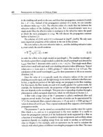
360
TRANSMISSION SYSTEM ENGINEERING
[Zir98] M. Zirngibl. Analytical model of Raman gain effects in massive wavelength
division multiplexed transmission systems.
Electronics Letters,
34:789, 1998.
[ZO94] J. Zhou and M. J. O'Mahony. Optical transmission system penalties due to fiber
polarization mode dispersion.
IEEE Photonics Technology Letters,
6(10):1265-1267, Oct. 1994.
[Zys96] J.L. Zyskind et al. Fast power transients in optically amplified multiwavelength
optical networks. In
0FC'96 Technical Digest,
1996. Postdeadline paper PD31.
Networks
This Page Intentionally Left Blank
Client Layers of the
Optical Layer
T
HIS CHAPTER
DESCRIBES
several networks that use optical fiber as their underlying
transmission mechanism. These networks can be thought of as client layers of
the optical layer. As we saw in Chapter 1, the optical layer provides lightpaths to the
client layers. To the client layer, these lightpaths look like physical links between client
layer network elements. All the client layers that we will study process the data in the
electrical domain, performing functions such as fixed time division multiplexing or
statistical time division multiplexing (packet switching). These client layers aggregate
and bring a variety of lower-speed voice, data, and private line services into the
network. Each of these client networks is important in its own right and can operate
over point-to-point fiber links as well as over a more sophisticated optical layer, using
the lightpaths provided by the optical layer.
The predominant client layers in backbone networks today are SONET/SDH, IP,
and ATM. SONET/SDH is particularly adept at dealing with lower-speed time divi-
sion multiplexed streams, whereas IP and ATM are adept at dealing with statistically
multiplexed packet streams. In many cases, IP and ATM use SONET/SDH as the
underlying transport mechanism. With the emergence of high-speed interfaces on IP
and ATM equipment, we are also seeing IP and ATM mapped directly into the optical
layer, without requiring separate SONET/SDH equipment. In the metro network, we
are seeing a proliferation of several types of client layers, such as Gigabit Ethernet,
ESCON, and Fibre Channel. Many of the latter networks are used to interconnect
computers and their peripherals in so-called storage-area networks.
In this chapter, we provide descriptions of these various networks, focusing
primarily on a qualitative understanding, as well as characteristics that are important
363
6.1
SONETISDH
-
SONET (Synchronous Optical Network) is the current transmission and multiplexing
standard for high-speed signals within the carrier infrastructure in North America.
A closely related standard, SDH (Synchronous Digital Hierarchy), has been adopted
in Europe and Japan and for most submarine links.
In order to understand the factors underlying the evolution and standardization
of SONET and SDH, we need to look back in time and understand how multiplexing
was done in the public network. Prior to SONET and SDH, the existing infrastruc-
ture was based on the
plesiochronous digital hierarchy
(PDH), dating back to the
mid-1960s. (North American operators refer to PDH as the
asynchronous
digital
hierarchy.) At that time the primary focus was
on
multiplexing digital voice circuits.
An analog voice circuit with a bandwidth of 4 kHz could be sampled at 8 kHz and
quantized at
8
bits per sample, leading to a bit rate of 64 kb/s for a digital voice
circuit. This became the widely accepted standard. Higher-speed streams were de-
fined as multiples of this basic 64 kb/s stream. Different sets of standards emerged
in different parts
of
the world for these higher-speed streams, as shown in Table 6.1.
In North America, the 64 kb/s signal is called DSO (digital signal-0), the 1.544 Mb/s
signal
is
DSI, the 44.736 Mb/s is DS3, and
so
on. In Europe, the hierarchy is labeled
EO, El, E2, E3, and
so
on, with the EO rate being the same as the DSO rate. These
rates are widely prevalent today in carrier networks and are offered as leased line
services by carriers to customers, more often than not to carry data rather than voice
traffic.
PDH suffered from several problems, which led carriers and vendors alike to seek
a new transmission and multiplexing standard in the late 1980s. This resulted in the
the SONET/SDH standards, which solved many problems associated with PDH. We
explain some
of
the benefits of SONET/SDH below and contrast
it
with PDH.
1.
Multiplexing simplification:
In asynchronous multiplexing, each terminal in the
network runs its own clock, and while we can specify a nominal clock rate for the
6.1 SONET/SDH
365
Table
6.1 Transmission rates for asynchronous and plesiochronous
signals, adapted from [SS96].
Level
North America
Europe Japan
0 0.064 Mb/s 0.064 Mb/s 0.064 Mb/s
1 1.544 Mb/s 2.048 Mb/s 1.544 Mb/s
2 6.312 Mb/s 8.448 Mb/s 6.312 Mb/s
3 44.736 Mb/s 34.368 Mb/s 32.064 Mb/s
4 139.264 Mb/s 139.264 Mb/s 97.728 Mb/s
signal, there can be significant differences in the actual rates between different
clocks. For example, in a DS3 signal, a 20 ppm (parts per million) variation
in clock rate between different clocks, which is not uncommon, can produce
a difference in bit rate of 1.8 kb/s between two signals. So when lower-speed
streams are multiplexed by interleaving their bits, extra bits may need to be
stuffed in the multiplexed stream to account for differences between the clock
rates of the individual streams. As a result, the bit rates in the asynchronous
hierarchy are not integral multiples of the basic 64 kb/s rate, but rather slightly
higher to account for this bit stuffing. For instance, a DS1 signal is designed
to carry 24 64 kb/s signals, but its bit rate (1.544 Mb/s) is slightly higher than
24 x 64 kb/s.
With asynchronous multiplexing, it is very difficult to pick out a low-bit-rate
stream, say, at 64 kb/s, from a higher-speed stream passing through, say, a DS3
stream, without completely demultiplexing the higher-speed stream down to its
individual component streams. This results in the need for "multiplexer moun-
tains," or stacked-up multiplexers, each time a low-bit-rate stream needs to be
extracted, as shown in Figure 6.1. This is a relatively expensive proposition and
also compromises network reliability because of the large amount of electronics
needed overall.
The synchronous multiplexing structure of SONET/SDH provides significant
reduction in the cost of multiplexing and demultiplexing. All the clocks in the
network are perfectly synchronized to a single master clock, and as a conse-
quence, the rates defined in SONET/SDH are integral multiples of the basic rate
and no bit stuffing is needed when multiplexing streams together. As a result, a
lower-speed signal can be extracted from a multiplexed SONET/SDH stream in
a single step by locating the appropriate positions of the corresponding bits in
the multiplexed signal. This makes the design of SONET multiplexers and de-
multiplexers much easier than their asynchronous equivalents. We will explore
this in more detail in Section 6.1.1.
366 CLIENT LAYERS OF THE OPTICAL LAYER
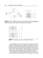
Figure
6.1 Comparison of asynchronous and synchronous multiplexing. (a) In the asyn-
chronous case, demultiplexers must be stacked up to extract a lower-speed stream from
a multiplexed stream. (b) In the synchronous case, this can be done in a single step using
relatively simple circuitry.
2. Management: The SONET and SDH standards incorporate extensive manage-
ment information for managing the network, including extensive performance
monitoring, identification of connectivity and traffic type, identification and re-
porting of failures, and a data communication channel for transporting man-
agement information between the nodes. This is mostly lacking in the PDH
standards.
3. Interoperability: Although PDH defined multiplexing methods, it did not define
a standard format on the transmission link. Thus different vendors used dif-
ferent line coding, optical interfaces, and so forth to optimize their products,
which made it very difficult to connect one vendor's equipment to another's via
a transmission link. SONET and SDH avoid this problem by defining standard
optical interfaces that enable interoperability between equipment from different
vendors on the link. Unfortunately, certain aspects of SONET and SDH were
only recently standardized, such as the data communication channel mentioned
above. As a result, even today, it is not trivial to interconnect SONET equipment
from different vendors.
4.
Network availability:
The SONET and SDH standards have evolved to incorpo-
rate specific network topologies and specific protection techniques and associ-
ated protocols to provide high-availability services. As a consequence, the service
restoration time after a failure with SONET and SDH is much smallermless than
60 msmthan the restoration time in PDH networks, which typically took several
seconds to minutes.
6.1 SONET/SDH 367
6.1.1
Multiplexing
SONET and SDH employ a sophisticated multiplexing scheme, which can, however,
be easily implemented in today's very large-scale integrated (VLSI) circuits. Although
SONET and SDH are basically similar, the terms used in SONET and SDH are
different, and we will use the SONET version in what follows and introduce the
SDH version wherever appropriate.
For SONET, the basic signal rate is 51.84 Mb/s, called the synchronous transport
signal level-1 (STS-1). Higher-rate signals (STS-N) are obtained by interleaving the
bytes from N frame-aligned STS-ls. Because the clocks of the individual signals are
synchronized, no bit stuffing is required. For the same reason, a lower-speed stream
can be extracted easily from a multiplexed stream without having to demultiplex the
entire signal.
The currently defined SONET and SDH rates are shown in Table 6.2. Note
that an STS signal is an electrical signal and in many cases (particularly at the
higher speeds) may exist only inside the SONET equipment. The interface to other
equipment is usually optical and is essentially a scrambled version of the STS signal in
optical form. Scrambling is used to prevent long runs of 0s or ls in the data stream.
(See Section 4.1.1 for a more detailed explanation of scrambling.) Each SONET
transmitter scrambles the signal before it is transmitted over the fiber, and the next
SONET receiver descrambles the signal. The optical interface corresponding to the
STS-3 rate is called OC-3 (optical carrier-3), and similar optical interfaces have been
defined for OC-12, OC-48, OC-192, and OC-768 corresponding to the STS-12,
STS-48, STS-192, and STS-768 signals.
For SDH, the basic rate is 155 Mb/s and is called STM-1 (synchronous transport
module-i). Note that this is higher than the basic SONET bit rate. The SONET
bit rate was chosen to accommodate the commonly used asynchronous signals,
which are DS1 and DS3 signals. The SDH bit rate was chosen to accommodate
the commonly used PDH signals, which are El, E3, and E4 signals. Higher-bit-rate
signals are defined analogous to SONET, as shown in Table 6.2.
A SONET frame consists of some overhead bytes called the
transport
overhead
and the payload bytes. The payload data is carried in the so-called synchronous
payload envelope (SPE). The SPE includes a set of additional
path
overhead bytes
that are inserted at the source node and remain with the data until it reaches its
destination node. For instance, one of these bytes is the
path trace,
which identifies
the SPE and can be used to verify connectivity in the network. We will study the
frame structure in more detail in Section 6.1.3.
SONET and SDH make extensive use of pointers to indicate the location of
multiplexed payload data within a frame. The SPE doesn't have a fixed starting point
within a frame. Instead, its starting point is indicated by a pointer in the line overhead.
368
CLIENT LAYERS OF THE OPTICAL LAYER
Table 6.2
from [SS96].
Transmission rates for SONET/SDH, adapted
SONET Signal SDH Signal Bit Rate (Mb/s)
STS-1 51.84
STS-3 STM-1 155.52
STS-12 STM-4 622.08
STS-24 1244.16
STS-48 STM-16 2488.32
STS-192 STM-64 9953.28
STS-768 STM-256 39, 814.32
Even though the clocks in SONET are all derived from a single source, there can be
small transient variations in frequency between different signals. Such a difference
between the incoming signal and the local clock used to generate an outgoing signal
translates into accumulated phase differences between the two signals. This problem
is easily solved by allowing the payload to be shifted earlier or later in a frame
and indicating this by modifying the associated pointer. This avoids the need for bit
stuffing or additional buffering. However, it does require a fair amount of pointer
processing, which can be performed easily in today's integrated circuits.
Lower-speed non-SONET streams below the STS-1 rate are mapped into
virtual
tributaries
(VTs). Each VT is designed to have sufficient bandwidth to carry its
payload. In SONET, VTs have been defined in four sizes: VT1.5, VT2, VT3, and VT6.
These VTs are designed to carry 1.5, 2, 3, and 6 Mb/s asynchronous/plesiochronous
streams, as shown in Figure 6.2. Of these, the VT1.5 signal is the most common, as it
holds the popular DS1 asynchronous signal. At the next level in the hierarchy, a VT
group consists of either four VT1.5s, three VT2s, two VT3s, or a single VT6. Seven
such VT groups are
byte
interleaved along with a set of path overheads to create a
basic
SONET SPE. Just as an SPE floats within a SONET frame, the VT payload
(called VT SPE) can also float within the STS-1 SPE, and a VT pointer is used to
point to the VT SPE. The pointer is located in two designated bytes within each VT
group. Figure 6.3 illustrates this pointer structure.
In many cases, it is necessary to map higher-speed non-SONET signals into an
SPE for transport over SONET. The most common examples today are probably
high-speed packet streams from IP routers or ATM switches. For this purpose, an
STS-Nc signal with a
locked
payload is also defined in the standards. The "c" stands
for
concatenated.
The concatenated or locked payload implies that this signal cannot
be demultiplexed into lower-speed streams. For example, a 150 Mb/s ATM signal is
6.1 SONET/SDH 369
DS1
1.544 Mb/s I I
VT1.5 SPE I
E1
2.048 Mb/s] ]
VT2 SPE I
DS1C
3.152
Mb/sll I
VT3 SPE ]
DS2
6.312 Mb/s I [
VT6 SPE ]
I
DS3
44.736 Mb/s
ATM
48.384 Mb/s
E4
139.264 Mb/s
ATM
149.760 Mb/s
(SPE +
path overhead)
~] VT1.5 • 4
~] VT2 x 3
x2
~1 VT3
~-[ VT6
VT
group
x7
~1 STS-1 SPE STS-1
Y'I
~l STS-3~ SPE STS-3~
STS-N
Figure 6.2
in SONET.
The mapping of lower-speed asynchronous streams into virtual tributaries
Figure 6.3 The use of pointers in a SONET STS-1 signal carrying virtual tributaries
(VTs). The STS payload pointer in the transport overhead points to the STS-1 synchronous
payload envelope (SPE) and the VT pointer inside the STS-1 SPE points to the VT SPE.