Optical Networks: A Practical Perspective - Part 43 doc
Bạn đang xem bản rút gọn của tài liệu. Xem và tải ngay bản đầy đủ của tài liệu tại đây (611.55 KB, 10 trang )
390 CLIENT LAYERS Or THE OPTICAL LAVE~
6.3.1
IP, being a network layer protocol, does not guarantee reliable, in-sequence deliv-
ery of data from source to destination. This job is performed by a transport protocol,
typically the
transmission control protocol
(TCP). Another commonly used transport
protocol for simple message transfers over IP is the
user datagram protocol
(UDP).
Commonly used applications, such as telnet, file transfer protocol (FTP), and rlogin,
use TCP as their transport protocol, whereas certain other applications, such as the
network file system (NFS) used to share files across a network and the simple network
management protocol (SNMP) used for management, use UDP for transport. (We
will talk about SNMP in Chapter 9.) UDP is also the transport protocol of choice
for streaming media.
Routing and Forwarding
IP was one of the earliest packet-switching protocols. IP transports information in
the form of packets, which are of variable length. An IP router is the key network
element in an IP network. A router forwards packets from an incoming link onto an
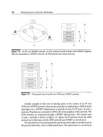
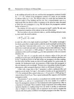
outgoing link. Figure 6.15 illustrates how packets are forwarded in an IP network.
The nature of this routing is fundamental to IP. Here we describe the classical routing
mechanism used by IP. Each router maintains a routing table. The routing table has
one or more entries for each destination router in the network. The entry indicates
the next node adjacent to this router to which packets need to be forwarded. The
forwarding process works as follows. The router looks at the header in a packet
arriving on an incoming link. The header contains the identity of the destination
router for that packet. The router then does a lookup of its routing table to determine
the next adjacent node for that packet, and forwards the packet on the link leading
to that node. In the example shown in Figure 6.15, consider a packet from node 1
destined for node 4. Node 1 looks at its table and forwards this packet to node 5.
Node 5 forwards the packet to node 3, which in turn forwards the packet to node
4, its ultimate destination.
Clearly, maintaining these routing tables at the routers is central to the operation
of the network. It is likely that links and nodes in the network may fail, or reappear,
and new links and nodes may be added over the course of time. The routers detect
these changes automatically and update their routing tables using a distributed
rout-
ing protocol.
The protocol works as follows. Each router is assumed to be capable
of determining whether its links to its neighbors are up or down. Whenever a router
detects a change in the status of these links, it generates a
link state packet
and
floods
it to all the routers in the network. Flooding is a technique used to disseminate in-
formation across the network. Each node, upon receiving a flood packet, forwards
the packet on all its adjacent links except the link it came from. Thus these packets
eventually reach all the nodes in the network. A node receiving a link state packet
6.3 IP 391
2
1 3
5
Dest. t hop
1 1 2
2 2 Dest. Next hop 2 2
3 5 1 1 3 -
4 5 2 1 4 4
5 5 3 3 5 5
4 3
5
4
A
w
Figure
6.15 Routing in an IP network. The routing tables at some of the nodes are also
shown. The tables contain the identity of the next hop node for each destination.
updates its routing table based on the new information. Over time, all nodes in the
network have updated routing tables that reflect the current network topology.
There are a number of subtle enhancements needed to make the flooding process
work reliably. For example, link state packets could take different paths through the
network and undergo different delays. As a result, an older link state packet might
arrive after a more recent up-to-date version. If left unchecked, this could cause
damage. Consider what happens when a link goes down and comes back up. The
first link state packet (packet X) says that the link is down and the subsequent one
(packet Y) indicates that the link is up. A node receiving packet X after packet Y will
think that the link is down, even after it has come up! To prevent this phenomenon,
the link state packets have a sequence number. If a router receives a link state packet
whose sequence number is lower than a previously received link state packet, it
simply discards the packet. Packets could also be lost in the network, so link state
updates are generated periodically and not just after a link up/down event occurs.
Using these link state packets, each router can construct its view of the entire
network topology. On this topology, each router then computes the shortest path
from itself to all the other routers and stores the identity of the next router in the
path for each destination node in its routing table. A typical shortest-path algorithm
used for this purpose is the Dijkstra algorithm [Dij59].
The routing protocol that we have described above is an example of an
in-
tradomain routing protocol.
One of the most commonly used intradomain routing
protocols in the
Internet~Open Shortest Path First (OSPF)~works just as we have
described above.
The Internet is a very large network, and it is impractical to expect each router to
maintain a topology of the entire Internet. For this purpose, the network is divided
392 CLIENT LAYERS or THE OPTICAL LAVER
into multiple interconnected domains. Each domain is called an
autonomous system
(AS). A separate
interdomain routing protocol
is used to route between domains
in a large network. One example of such a protocol is the
border gateway protocol
(BGP), details of which the reader can find in the references at the end of this chapter.
6.3.2
Quality of Service
IP networks traditionally offer "best-effort" services. IP tries its best to get a packet
from its source to its destination. However, different packets may take different
routes through the network and experience random delays, and some packets will be
dropped if there is congestion in the network. There has been a great deal of effort
to improve this state of affairs so as to offer some quality-of-service (QoS) assurance
to the users of the network. Within IP, a mechanism called Diff-Serv (differentiated
services) has been proposed. In Diff-Serv, packets are grouped into different classes,
with the class type indicated in the IP header. The class type specifies how packets
are treated within each router. Packets marked as
expedited forwarding
(EF) are
handled in a separate queue and routed through as quickly as possible. Several
additional priority levels of
assured forwarding
(AF) are also specified. An AF has
two attributes:
xy.
The attribute x typically indicates the queue to which the packet is
held in the router prior to switching. The attribute y indicates the drop preference for
the packets. Packets with y = 3 have a higher likelihood of being dropped, compared
to packets with y = 1.
While Diff-Serv attempts to tackle the QoS issue, it does not provide any end-
to-end method to guarantee QoS. For example, we cannot determine a priori if
sufficient bandwidth is available in the network to handle a new traffic stream
with real-time delay requirements. This is one of the benefits of multiprotocol label
switching, which we will study next.
6.3.3
Multiprotocol Label Switching (MPLS)
MPLS is a new technology in the IP world and has a wide variety of applications.
MPLS can be thought of as a layer sandwiched between the IP layer and the data link
layer. MPLS provides a label-switched path (LSP) between nodes in the network. A
router implementing MPLS is called a label-switched router (LSR). Each packet now
carries a label that is associated with a label-switched path. Each LSR maintains a
label-forwarding table, which specifies the outgoing link and outgoing label for each
incoming label. When an LSR receives a packet, it extracts the label, uses it to index
into the forwarding table, replaces the incoming label with the outgoing label, and
forwards the packet on to the link specified in the forwarding table. Note that the
6.3 IP 393
processing of actually setting up label-switched paths is a control function that is
completely decoupled from the forwarding action taking place within each LSR.
This very simple MPLS paradigm has several applications in an IP network.
One of the fundamental design philosophies in MPLS is that the label-switching and
packet-forwarding process at each router is completely decoupled from how LSPs
are set up and taken down in the network. We can think of the latter as a network
control function, which involves first deciding what LSPs to set up or take down and
then actually setting them up and taking them down. This simple separation allows
us to build optimized hardware for packet forwarding, independent of the network
control mechanisms, and allows for LSPs to be set up and taken down based on
different criteria and using different protocols.
An LSR doing label forwarding can potentially process a much larger number
of packets per second compared to a regular router because the label switching and
forwarding process is much simpler than classical IP routing and can be implemented
almost entirely in hardware. While many of the functions of classical IP routing
discussed in the previous section can also be implemented in hardware, there is a
close coupling between the routing function and the control function in IP. Any
changes to the control framework get reflected in the routing behavior. As a result,
existing hardware will not continue to remain optimized for routing if the control
framework changes. In contrast, in MPLS, we can optimize the forwarding hardware
in the LSRs, independent of how label-switched paths are set up or taken down.
Another major benefit of MPLS is that it introduces the notion of a path in an
IP network. IP traditionally switches packets, or datagrams, and has no notion of
end-to-end paths. Different packets between the same pair of routers could take
different routes through the network, based on the current state of the routing
tables at the routers. The ability to specify paths along which packets can be routed
has several implications. First, a service provider owning a network can now plan
end-to-end routes for packets based on a variety of criteria. For example, it could
plan routes so as to optimize the use of bandwidth in its network. It could plan
routes to prevent some links from getting congested while other links are idle.
The ability to have explicity routed paths also allows a service provider to offer
certain QoS assurances for selected traffic in the network. IP itself has traditionally
offered "best-effort" service. As we said earlier, different packets could take different
routes and could therefore arrive at their destinations with random delays. Moreover,
it is quite possible and likely that this type of routing can cause congestion, or hot
spots in parts of the network, causing a large number of packets to be dropped in
the network. With MPLS, we could potentially reserve bandwidth along the links at
the time an LSP is set up, to enable QoS guarantees.
Packets belonging to an LSP can be rerouted rapidly onto another LSP if there is
a failure in the network. For example, we could set up two LSPs between a pair of
394
CLIENT LAYERS OF THE OPTICAL LAYER
6.3.4
nodes along diverse paths. If an LSP fails, we can reroute packets from that LSP to
the other LSP and ensure rapid restoration of service. We will see in Chapter 10 that
the IP routing mechanism itself cannot be relied upon to provide rapid rerouting of
packets in case of a failure. Thus, MPLS can be used to provide rapid restoration
times in an IP network in the case of failures.
Finally, MPLS can also be used to support multiple
virtual private networks
(VPNs) over a single IP network. Each VPN is carried over a separate set of LSPs,
allowing the service provider to provide QoS, security, and other policy measures on
a VPN-specific basis.
Deciding which LSPs to set up in a network can be a complicated process,
depending on the objectives and the application. Luckily, as we indicated earlier,
this function is completely decoupled from the label-switching mechanism in the
LSRs. For example, if the objective is simply to reduce packet delay, we might set up
LSPs between pairs of nodes with a lot of traffic between them. If the objective is to
provide QoS guarantees, we would set up LSPs based on the bandwidth availability
in the network.
Two signaling protocols are now available to set up LSPs across a network the
resource reservation protocol (RSVP) and the label distribution protocol with con-
strained routing
(CR-LDP). Both protocols operate by sending a setup message from
the source of the LSP to the destination of the LSP along the desired path on a
hop-by-hop basis. Each LSR along the path determines if resources to support the
LSP are available before passing on the setup message to the next LSR in the path. An
acknowledgment message then flows back from the destination to the source along
the path to complete the process.
Whither ATM?
Readers will note that almost all the capabilities of MPLS are offered by ATM. In fact,
prior to the development of MPLS, ATM was viewed as the layer below IP, with which
all the MPLS functions described above could be provided. Indeed, as of this writing,
the various ATM protocols are much better developed and standardized, compared
to MPLS. ATM was initially viewed as a replacement for IP~its fixed cell size allows
high-speed switches to be designed, and its connection-oriented nature and superior
QoS capabilities allow better transport of voice, video, and other real-time traffic over
packet networks. However, IP appears to have won the day primarily because of its
ubiquitymit is widely deployed in everything ranging from desktop computers to core
routers and is hard to displace. As a result, the ATM standards have defined interfaces
so that IP can operate using ATM as its immediately lower layer. The development
of MPLS appears to threaten this use of ATM as well. You could argue that MPLS
is better optimized for use in data networks because it allows larger packet sizes
6.4 Storage-Area Networks
395
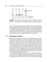
Figure 6.16 Architecture of a storage-area network.
(1500 bytes) compared to ATM's 53-byte cells. Interestingly, many MPLS routers
use ATM switch fabrics internally to perform high-speed packet forwarding, so at
least this aspect of ATM may continue to exist.
6.4
Storage-Area Networks
Storage-area networks (SANs) are networks used to interconnect computer systems
with other computer systems and peripheral equipment, such as disk drives, printers,
and tape drives. These networks are built by enterprises having medium to large
data centers. Figure 6.16 shows a typical SAN interconnecting multiple CPUs and
various types of peripheral devices. A key part of a SAN is a switch, which provides
reconfigurable connectivity between the various attached devices. The SANs that we
consider below all use a circuit-switched approach, where connections are rapidly
established and taken down between the attached devices as needed.
In early installations, the entire SAN was located within a building or campus,
but today the network is distributed over a wider metropolitan area, with some links
extending into the long-haul network. One reason to do so is to be able to provide
resilience against disasters. A common technique is to maintain two data centers,
with data from one center backed up onto the other. Another reason to distribute the
network is to locate peripherals and other equipment away from major downtown
areas into cheaper suburban areas where real estate is less expensive.
SANs today typically operate at bit rates ranging from 200 Mb/s to 1 Gb/s and
operate over fiber optic links in most cases. While the bit rate itself is relatively
modest, what makes SANs important from the perspective of the optical layer is that
396 CLIENT LAYERS OF THE OPTICAL LAYER
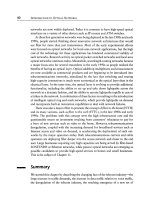
Table 6.4 Different storage-area networks. The fiber interfaces use either light emitting
diodes (LEDs) and multimode fiber (MMF) or multilongitudinal mode laser (MLM)
transmitters and standard single-mode fiber (SMF).
Network Data
Rate Transmission Rate Physical Interface
(MBytes/s)
(Mbaud)
ESCON
HIPPI
HIPPI (serialized)
Fibre Channel
17 2OO LED/MMF
MLM/SMF
100 parallel copper
100 1200 MLM/SMF
100 1063 MLM/SMF or copper
50 531 MLM/SMF or copper
25 266 MLM/SMF or copper
12.5 133 MLNUSMF or copper
200 2126 MLM/SMF
400 4252 MLM/SMF
there can be a huge number of such connections between two data centers. Large
mainframes have hundreds of I/O channels to connect them to other devices. It is
not uncommon to see networks with hundreds to thousands of these links between
two data centers.
The two main SAN technologies today are ESCON (enterprise serial connection)
and Fibre Channel, with Fibre Channel dominating new installations. In addition,
an older standard, called HIPPI (high performance parallel interface) is widely used
in supercomputer and high-end computing installations.
Table 6.4 summarizes the salient attributes of ESCON, HIPPI, and Fibre Channel.
These protocols typically add overhead to the data and then use line coding to encode
the signal for transmission over the fiber. In each case, we have indicated the data
rate as well as the actual transmission rate over the fiber, which is obtained after
adding overheads and line coding. The latter rate is usually called the baud rate; thus
we say the transmission rate is 1062.5 Mbaud rather than 1062.5 Mb/s.
6.4.1
ESCON
ESCON was developed by IBM in the late 1980s to replace the cumbersome,
low-speed, and limited number of copper-based I/O interfaces on mainframe com-
puters. It is widely deployed in large mainframe installations.
The data rate per ESCON channel is 17 MBytes/s. The transmission rate over the
fiber after line coding and overheads is 200 Mbaud. LEDs at 1.3/xm are used over
6.4 Storage-Area Networks
397
multimode fiber if the link length is less than 3 km. Longer distances, up to 20 km,
are supported by using 1.3 #m MLM lasers over single-mode fiber.
One of the limiting factors of ESCON is that it uses a stop-and-wait link layer
protocol. After sending a block of data, the sender waits for an acknowledgment
from the receiver before sending the next block. As a result, the throughput on the
links drops as the length of the link increases. To some extent, this can be offset by
using larger block sizes. For this reason, many ESCON devices specify the maximum
interconnection distance with other devices separately from the allowed link loss on
the fiber link.
ESCON uses an (8, 10) line code (see Section 4.1.1) to avoid long runs of 0s or
ls and to achieve DC balance, that is, equal numbers of transmitted 0 and 1 bits.
6.4.2
Fibre Channel
Fibre Channel is a standard developed in the early 1990s, used for the same set of
applications as ESCON. Like ESCON, the Fibre Channel architecture includes I/O
ports on computers and peripherals, as well as an electronic switch. Fibre Channel
is now widely deployed. The standard allows a variety of data rates. The most
popular rate in use today is the "full speed" 100 MBytes/s rate; higher rates have
been defined as shown in Table 6.4. Quarter-speed (25 MBytes/s) interfaces have also
been deployed. Fibre Channel uses the same (8, 10) line code (see Section 4.1.1) as
ESCON.
Both copper and fiber interfaces have been defined, with the fiber interface widely
used in practice. Shielded twisted-pair copper interfaces are also deployed up to the
100 MBytes/s rate.
6.4.3
HIPPI
HIPPI is a 100 MBytes/s parallel electrical I/O interface standard. Owing to clock
skew, the maximum distance is limited to 25 m. For longer distances, HIPPI is
serialized and transmitted over single-mode fiber. A modified standard called Serial
HIPPI, which includes an optical interface at 1.2 Gbaud, has been defined recently for
this purpose. The standard also supports a 200 MBytes/s serial interface using two
100 MBytes/s serial interfaces in parallel. Work is also under way toward defining a
12-fiber version of the protocol, each fiber supporting a 100 MBytes/s data rate.
HIPPI predates Fibre Channel and is widely deployed in supercomputer instal-
lations. Like ESCON and Fibre Channel, a HIPPI network consists of hosts and
peripherals connected via HIPPI switches and, in many cases, serial fiber optic links.
398 CLIENT LAYERS OF THE OPTICAL LAVER
6.5
Gigabit and 10-Gigabit Ethernet
Ethernet is the most popular local-area packet-switched network today. The original
Ethernet operated at 10 Mb/s and was then upgraded to 100 Mb/s. Ethernet is based
on a bus architecture where all the nodes are connected to a single bus. The nodes
use a simple media access control protocol called carrier-sense multiple access with
collision detect (CSMA/CD). A node wanting to send a packet senses the bus to see
if it is idle. Upon detecting that it is idle, it transmits the packet. If another node
happens to sense the bus at the same time and transmits a packet, the two packets
collide and get corrupted. In this case, both nodes back off and attempt to transmit
again after waiting for a randomized delay interval. At higher speeds and longer bus
lengths, the efficiency of the protocol drops. For this reason, Ethernet is also deployed
in point-to-point configurations with only two nodes on the bus. An Ethernet switch
is used to interconnect multiple such busses.
Gigabit Ethernet is an extension of the same standard to 1 Gb/s. It operates over
both copper and fiber interfaces. Gigabit Ethernet over fiber is becoming a popular
choice in metro networks to interconnect multiple enterprise networks. It is also
extending its tentacles into the long-haul network.
Currently, there is work under way to extend the Ethernet standard to 10 Gb/s.
This standard is being developed with the intent of enabling long-haul interconnec-
tions, with the data rate being aligned to the OC-192/STM-64 SONET/SDH rates
for better compatibility with wide-area transport.
Summary
In this chapter, we studied several important client layers of the optical layer. These
have been deployed widely in public telecommunications networks as well as private
enterprise networks. The public transmission infrastructure in North America is
dominated by SONET; SDH is used in most other parts of the world. SONET/SDH
provides efficient time division multiplexing for low-speed streams and allows these
streams to be transported across the network in a reliable, well-managed way. The
predominant network layer protocol today is IP. Most of the data traffic entering the
network is IP traffic, spurred by the growth of the Internet and corporate intranets. IP
provides primarily best-effort routing of packets from their source to destination and
has no notion of connections. A new link layer, MPLS, is emerging below the IP layer,
to expand the scope of IP to allow explicit routing of packets along defined paths
through the network. ATM is another protocol that provides similar capabilities.
Storage-area networks area constitute another important class of networks using
optical fiber for transmission. These are used to link up computers to other computers
Problems
399
and their peripherals. ESCON, HIPPI, and Fibre Channel are all widely deployed,
with Fibre Channel being more popular for new deployments.
Further Reading
A general reference that covers SONET, IP, and ATM is the book by Walrand and
Varaiya [WV00]. There is an extensive body of literature dealing with SONET/SDH.
A comprehensive set of papers that cover the multiplexing standards, network
topologies, and performance and management is collected in [SS96]. See also the
book by Sexton and Reid [SR97] for an advanced treatment of the subject and
[Gor00] as well. SONET/SDH has been extensively standardized by the Ameri-
can National Standards Institute (ANSI) and the International Telecommunications
Union (ITU). In addition, Telcordia publishes generic criteria for equipment ven-
dors. A list of the standards documents may be obtained on the World Wide Web at
www.itu.ch, www.ansi.org,
and
www.telcordia.com;
some of them are listed in Ap-
pendix C. Telcordia's GR-253 [Tel99] contains an extensive description of SONET,
which we have made liberal use of in this chapter.
Readers wanting to learn about ATM and IP will be deluged with information.
There are several books on ATM. See, for instance, [dP95, MS98]. The ATM forum
(www.atmforum.com)
maintains and makes available the ATM standards.
For an introductory overview of IP, see [PD99, Per99]. See [Corn00, Ste94] for a
more detailed treatment of TCP/IP, and [DR00] for MPLS. The Internet Engineering
Task Force
(www.ietf.org)
develops and maintains standards, with all standards
documents (RFCsmrequest for comments) being readily available.
ESCON was invented at IBM in the late 1980s [CdLS92, ES92]. It was
subsequently standardized by ANSI as SBCON [Ame97]. ANSI standards have
been established for HIPPI and Fibre Channel as well. [Cla99, TS00] provide
primers on storage-area networks in general, focusing on Fibre Channel solu-
tions. See
www.hippi.org
for HIPPI, including pointers to the HIPPI standards, and
[Ame98, Ben96, SV96] as well as
www.fibrechannel.org
for Fibre Channel. Finally,
the Ethernet standards are available from ANSI. See
www.gigabit-ethernet.org
for
details on Gigabit Ethernet.
6.1
Problems
Which sublayer within the SONET or optical layer would be responsible for handling
the following functions?
(a) A SONET path fails and the traffic must be switched over to another path.