Optical Networks: A Practical Perspective - Part 46 ppt
Bạn đang xem bản rút gọn của tài liệu. Xem và tải ngay bản đầy đủ của tài liệu tại đây (1006.39 KB, 10 trang )
420 WDM NETWORK ELEMrNTS
Figure
7.8 Using an OXC in the network. The OXC sits between the client equipment
of the optical layer and the optical layer OLTs.
the surrounding OLTs, because carriers view crossconnects and OLTs as separate
products and often buy OXCs and OLTs from different vendors.
An OXC provides several key functions in a large network:
Service provisioning. An OXC can be used to provision lightpaths in a large network
in an automated manner, without having to resort to performing manual patch
panel connections. This capability becomes important when we deal with large
numbers of wavelengths in a node or with a large number of nodes in the
network. It also becomes important when the lightpaths in the network need to
be reconfigured to respond to traffic changes. The manual operation of sending
a person to each office to implement a patch panel connection is expensive and
error prone. Remotely configurable OXCs take care of this function.
Protection.
Protecting lightpaths against fiber cuts and equipment failures in the
network is emerging as one of the most important functions expected from a
crossconnect. The crossconnect is an intelligent network element that can detect
failures in the network and rapidly reroute lightpaths around the failure. Cross-
connects enable true mesh networks to be deployed. These networks can provide
particularly efficient use of network bandwidth, compared to the SONET/SDH
rings we discussed in Chapter 6. We discuss this topic in detail in Chapter 10.
Bit
rate transparency.
The ability to switch signals with arbitrary bit rates and frame
formats is a desirable attribute of OXCs.
Performance monitoring, test access, and fault
localization. OXCs provide visibil-
ity to the performance parameters of a signal at intermediate nodes. They usually
7.4 Optical Crossconnects 421
allow test equipment to be hooked up to a dedicated test port where the sig-
nals passing through the OXC can be monitored in a non-intrusive manner.
Non-intrusive test access requires
bridging
of the input signal. In bridging, the
input signal is split into two parts. One part is sent to the core, and the other
part is made available at the test access port. OXCs also provide loopback ca-
pabilities. This allows a lightpath to be looped back at intermediate nodes for
diagnostic purposes.
Wavelength conversion.
In addition to switching a signal from one port to another
port, OXCs may also incorporate wavelength conversion capabilities.
Multiplexing and grooming.
OXCs typically handle input and output signals at op-
tical line rates. However, they can incorporate multiplexing and grooming ca-
pabilities to switch traffic internally at much finer granularities, such as STS-1
(51 Mb/s). Note that this time division multiplexing has to be done in the elec-
trical domain and is really SONET/SDH multiplexing, but incorporated into the
OXC, rather than in a separate SONET/SDH box.
An OXC can be functionally divided into a switch core and a port complex.
The switch core houses the switch that performs the actual crossconnect function.
The port complex houses port cards that are used as interfaces to communicate with
other equipment. The port interfaces may or may not include optical-to-electrical
(O/E) or optical-to-electrical-to-optical (O/E/O) converters.
Figure 7.9 shows different types of OXCs and different configurations for inter-
connecting OXCs with OLTs or OADMs in a node. The scenarios differ in terms
of whether the actual switching is done electrically or optically, in the use of O/E
and O/E/O converters, and how the OXC is interconnected to the surrrounding
equipment. Table 7.2 summarizes the main differences between these architectures.
The first three configurations shown in Figure 7.9 are
opaque
configurations the
optical signal is converted into the electrical domain as it passes through the node. The
last configuration (Figure 7.9(d)) is an
all-optical
configuration the signal remains
in the optical domain as it passes through the node.
Looking at Figure 7.9, observe that in the opaque configurations the switch core
can be electrical or optical; that is, signals may be switched either in the electrical
domain or in the optical domain. An electrical switch core can groom traffic at
fine granularities and typically includes time division multiplexing of lower-speed
circuits into the line rate at the input and output ports. Today, we have electrical core
OXCs switching signals at granularities of STS-1 (51 Mb/s) or STS-48 (2.5 Gb/s). In
contrast, a true optical switch core does not offer any grooming. It simply switches
signals from one port to another.
An electrical switch core is designed to have a total switch capacity, for instance,
1.28 Tb/s. This capacity can be utilized to switch, say, up to 512 OC-48 (2.5 Gb/s)
422
WDM NETWORK ELEMENTS
Figure
7.9 Different scenarios for OXC deployment. (a) Electrical switch core; (b)
optical switch core surrounded by O/E/O converters; (c) optical switch core directly
connected to transponders in WDM equipment; and (d) optical switch core directly
connected to the multiplexer/demultiplexer in the OLT. Only one OLT is shown on either
side in the figure, although in reality an OXC will be connected to several OLTs.
signals or 128 OC-192 (10 Gb/s) signals. The optical core is typically bit rate inde-
pendent. Therefore a 1000-port optical switch core can switch 1000 OC-48 streams,
1000 OC-192 streams, or even 1000 OC-768 (40 Gb/s) streams, all at the same cost
per port. The optical core is thus more scalable in capacity, compared to an electrical
core, making it more future proof as bit rates increase in the future. In particular, the
configuration of Figure 7.9(d) allows us to switch groups of wavelengths or all the
wavelengths on a fiber together on a single OXC port, making that configuration
capable of handling enormous overall capacities, and reducing the number of OXC
ports required in a node.
As bit rates increase, the cost of a port on an electrical switch increases. For
instance, an OC-192 port might cost twice as much as an OC-48 port. The cost of
7.4 Optical Crossconnects
423
Table
7.2 Comparison of different OXC configurations. Some configurations use optical to elec-
trical converters as part of the crossconnect, in which case, they are able to measure electrical
layer parameters such as the bit error rate (BER) and invoke network restoration based on this
measurement. For the first two configurations, the interface on the OLTs is typically a SONET
short-reach (SR), or very-short-reach (VSR) interface. For the opaque photonic configuration, it is
an intermediate-reach (IR) or a special VSR interface. The cost, power, and footprint comparisons
are made based on characteristics of commercially available equipment at OC-192 line rates.
Attribute
Opaque Opaque Opaque All-Optical
Electrical Optical Optical
with
O/E/Os
Figure 7.9(a) Figure 7.9(b) Figure 7.9(c) Figure 7.9(d)
Low-speed grooming Yes No No No
Switch capacity Low High High Highest
Wavelength conversion Yes Yes Yes No
Switching triggers BER BER Optical power Optical power
Interface on OLT SR/VSR SR/VSR IR/serial VSR Proprietary
Cost per port Medium High Medium Low
Power consumption High High Medium Low
Footprint High High Medium Low
a port on an optical core switch, on the other hand, is the same regardless of the
bit rate. Therefore at higher bit rates, it will be more cost-effective to switch signals
through an optical core OXC than an electrical core OXC.
An optical switch core is also transparent; it does not care whether it is switching
a 10 Gb/s Ethernet signal or a 10 Gb/s SONET signal. In contrast, electrical switch
cores require separate port cards for each interface type, which convert the input
signal into a format suitable for the switch fabric.
Figure 7.9(a) shows an OXC consisting of an electrical switch core surrounded
by O/E converters. The OXC interoperates with OLTs through standard non-WDM
short-reach (SR) optical interfaces, typically at 1310 nm. We are also seeing the
deployment of cheaper very-short-reach (VSR) interfaces. The OLT has transpon-
ders to convert this signal into the appropriate WDM wavelength. Alternatively the
OXC itself may have wavelength-specific lasers that operate with the OLTs without
requiring transponders between them.
Figure 7.9(b)-(d) show OXCs with an optical switch core. The differences
between the figures lie in how they interoperate with the WDM equipment. In
Figure 7.9(b), the interworking is done in a somewhat similar fashion as in Fig-
ure 7.9(a)~through the use of O/E/O converters with short-reach or very-short-reach
optical interfaces between the OXC and the OLT. In Figure 7.9(c), there are no O/E/O
424 WDM NETWORK ELEMENTS
converters and the optical switch core directly interfaces with the transponders in
the OLT. Figure 7.9(d) shows a different scenario where there are no transponders
in the OLT and the wavelengths in the fiber are directly switched by the optical
switch core in the OXC after they are multiplexed/demultiplexed. The cost, power,
and overall node footprint all improve as we go from Figure 7.9(b) to Figure 7.9(d).
The electrical core option typically uses higher power and takes up more footprint,
compared to the optical option, but the relative cost depends on how the different
products are priced, as well as the operating bit rate on each port.
The OXCs in Figure 7.9(a) and (b) both have access to the signals in the electrical
domain and can therefore perform extensive performance monitoring (signal identi-
fication and bit error rate measurements). The bit error rate measurement can also
be used to trigger protection switching. Moreover, they can signal to other network
elements by using inband overhead channels embedded in the data stream. (We will
study signaling in more detail in Chapter 9.)
The OXCs in Figure 7.9(c) and (d) do not have the capability to look at the
signal, and therefore they cannot do extensive signal performance monitoring.
Thus, they cannot, for instance, invoke protection switching based on bit error
rate monitoring, but instead could use optical power measurement as a trigger.
These crossconnects need an out-of-band signaling channel to exchange control in-
formation with other network elements. With the configuration of Figure 7.9(c),
the attached equipment needs to have optical interfaces that can deal with the loss
introduced by the optical switch. These interfaces will also need to be single-mode
fiber interfaces since that is what most optical switches are designed to handle. In
addition, serial interfaces (single fiber pair) are preferred rather than parallel in-
terfaces (multiple fiber pairs), as each fiber pair consumes a port on the optical
switch.
The all-optical configuration of Figure 7.9(d) provides a truly all-optical net-
work. However, it mandates a more complex physical layer design (see Chapter 5) as
signals are now kept in the optical domain all the way from their source to their des-
tination, being switched optically at intermediate nodes. Given that link engineering
is complex and usually vendor proprietary, it is not easy to have one vendor's OXC
interoperate with another vendor's OLT in this configuration.
Note also that the configurations of Figure 7.9(b), (c), and (d) can all be combined
in a single OXC. We could have some ports having O/E/Os, others connected to OLTs
with O/E/Os, and still others connected to OLTs without any O/E/Os.
It is possible to integrate the OXC and OLT systems together into one piece of
equipment. Doing so provides some significant benefits. It eliminates the need for
redundant O/E/Os in multiple network elements, allows tight coupling between the
two to support efficient protection, and makes it easier to signal between multiple
OXCs in a network using the optical supervisory channel available in the OLTs. For
7.4 Optical Crossconnects
425
7.4.1
example, in Figure 7.9(a), we could have WDM interfaces directly on the crosscon-
nect and eliminate the intraoffice short-reach interface. We would migrate from the
configuration in Figure 7.9(b) to the configuration in Figure 7.9(c).
However, this integration also has the drawback of making it a single-vendor
solution. Service providers must then buy all their WDM equipment, including OLTs
and OXCs, from the same vendor in order to realize this simplification. Some ser-
vice providers prefer to build their network by mixing and matching "best-in-class"
equipment from multiple vendors. Moreover, this solution doesn't address the prob-
lem of dealing with legacy situations where the OLTs are already deployed and OXCs
must be added later.
All-Optical OXC Configurations
We now focus the discussion on understanding some of the issues associated with the
all-optical configuration of Figure 7.9(d). As shown, the configuration can be highly
cost-effective relative to the other configurations, but lacks three key functions:
low-speed grooming, wavelength conversion, and signal regeneration. Low-speed
grooming is needed to aggregate the lower-speed traffic streams properly for trans-
mission over the fiber. Optical signals need to be regenerated once they have propa-
gated through a number of fiber spans and/or other lossy elements.
Wavelength conversion is needed to improve the utilization of the network.
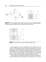
We illustrate this with the simple example shown in Figure 7.10. Each link in the
three-node network can carry three wavelengths. We have two lightpaths currently
set up on each link in the network as shown and need to set up a new lightpath
from node A to node C. Figure 7.10(a) shows the case where node B cannot perform
wavelength conversion. Even though there are free wavelengths available in the
network, the same wavelength is not available on both links in the network. As a
result, we cannot set up the desired lightpath. On the other hand, if node B can
convert wavelengths, then we can set up the lightpath as shown in Figure 7.10(b).
Note the configurations of Figure 7.9(a), (b), and (c) all provide wavelength
conversion and signal regeneration either in the OXC itself or by making use of the
transponders in the attached OLTs. Figure 7.9(a) also provides low-speed grooming,
assuming that the electrical core has been designed to support that capability. In
order to provide grooming, signal regeneration, and wavelength conversion, the
configuration of Figure 7.9(d) is modified to include an electrical core crossconnect
as shown in Figure 7.11. This configuration allows most of the signals to be switched
in the optical domain, minimizing the cost and maximizing the capacity of the
network, while allowing us to route the signals down to the electrical layer whenever
necessary. As we discussed earlier, we could save optical switch ports by switching
signals through in wavelength bands or even entire fibers at a time.
426
WDM NETWORK ELEMENTS
Figure 7.10 Illustrating the need for wavelength conversion. (a) Node B does not con-
vert wavelengths. (b) Node B can convert wavelengths.
Figure 7.11 A realistic "all-optical" network node combining optical core crosscon-
nects with electrical core crossconnects. Signals are switched in the optical domain when-
ever possible but routed down to the electrical domain whenever they need to be groomed,
regenerated, or converted from one wavelength to another.
7.4 Optical Crossconnects 427
Looking at Figure 7.11, note that the optical switch does not have to switch
signals from any input port to any output port. For example, it does not need to
switch a signal entering at wavelength )~1 to an output port that is connected to a
multiplexer that takes in wavelength k2. This allows some potential simplification
by making use of
wavelength planes.
Figure 7.12 shows a wavelength plane OXC. The signals coming in over different
fiber pairs are first demultiplexed by the OLTs. All the signals at a given wavelength
are sent to a switch dedicated to that wavelength, and the signals from the outputs
of the switches are multiplexed back together by the OLTs. In a node with F WDM
fiber pairs and W wavelengths on each fiber pair, this arrangement uses F OLTs
and W 2F x 2F switches. This allows any or all signals on any input wavelength
to be dropped locally. In contrast, the configuration of Figure 7.11 uses F OLTs
and a
2WF x 2WF
switch to provide the same capabilities. Consider, for example,
F = 4, W = 32, which are realistic numbers today. In this case, the configuration of
Figure 7.12 uses four OLTs and 32 8 x 8 switches. In contrast, Figure 7.9(b) requires
four OLTs and a 256 x 256 switch. As we saw in Section 3.7, larger optical switches
are significantly harder to build than small ones and will need to use technologies like
analog beam-steering micromirrors, whereas small optical switches can be realized
using a variety of different technologies.
Based on the discussion above, it would appear that the wavelength plane ap-
proach offers a cheaper alternative to large-scale nonblocking optical switches. How-
ever, we did not consider how to optimize the number of add/drop terminations
(which would be transponders or O/E interfaces on electrical switch cores). Both
Figure 7.11 and Figure 7.12 assume that there are sufficient ports to terminate all
WF signals. This is almost never the case, as only a fraction of traffic will need to be
dropped, and the terminations are expensive. Moreover, observe that if we indeed
do need
W F
terminations on an electrical switch, the best solution is to use the
electrical core configuration of Figure 7.9(a), without having the wavelength plane
switches!
If we have a total of T terminations, with all of them having tunable lasers, and
we would like to drop any of the
W F
signals, this requires an additional T x
W F
optical switch between the wavelength plane switches and the terminations, as shown
in Figure 7.13. In contrast, with a large nonblocking switch, we would simply connect
the T terminations to T ports of this switch, resulting in a
(WF + T) x (WF + T)
switch overall. This situation somewhat reduces the appeal of a wavelength plane
approach.
To summarize, the wavelength plane approach needs to take into account the
number of fibers, fraction of add/drop traffic, number of terminations, and their
tuning capabilities as separate parameters in the design. With a large-scale switch,
we can partition the ports in a flexible way to account for variations in all these
428 WDM NETWORK ELEMENTS
Figure 7.12 An optical core wavelength plane OXC, consisting of a plane of optical
switches, one for each wavelength. With F fibers and W wavelengths on each fiber, each
switch is a 2F x 2F switch, if we want the flexibility to drop and add any wavelength at
the node.
parameters the only constraint is in the total number of ports available. See Prob-
lem 7.7 for another example of these types of trade-offs.
As of this writing, both electrical core and optical core OXCs are becoming
available. Electrical core OXCs with total capacities up to a few Tb/s, capable of
grooming down to STS-1 (51 Mb/s), are becoming available. Optical core OXCs
with over 1000 ports are also emerging as commerical products, and wavelength
plane OXCs are being offered by some vendors as well.
Summary
We studied the basic network elements constituting WDM networks in this chap-
ter. We refer the reader back to Chapter 3 to get an understanding of the various
technologies that are used to build these elements.
The WDM network provides circuit-switched lightpaths that can have varying
degrees of transparency associated with them. Wavelengths can be reused in the
network to support multiple lightpaths as long as no two lightpaths are assigned the
same wavelength on a given link. Lightpaths may be protected by the network in
Summary
429
Figure
7.13 Dealing with add/drop terminations in a wavelength plane approach. An
additional optical switch is required between the tunable transponders and the wave-
length plane switches. Here, T denotes a transmitter, assumed to be a tunable transmitter
on the WDM side, and R denotes a receiver.
the event of failures. Lightpaths can be used to provide flexible interconnections
between users of the optical network, such as IP routers, allowing the router topology
to be tailored to the needs of the router network.
An optical line terminal (OLT) multiplexes and demultiplexes wavelengths and is
used for point-to-point applications. It typically includes transponders, multiplexers,
and optical amplifiers. Transponders provide the adaptation of user signals into the
optical layer. They also consitute a significant portion of the cost and footprint in
an OLT. In some cases, transponders can be eliminated by deploying interfaces that
provide already-adapted signals at the appropriate wavelengths in other equipment.
An optical add/drop multiplexer (OADM) drops and adds a selective number of
wavelengths from a WDM signal, while allowing the remaining wavelengths to pass
through. OADMs provide a cost-effective way of performing this function, compared