Optical Networks: A Practical Perspective - Part 47 potx
Bạn đang xem bản rút gọn của tài liệu. Xem và tải ngay bản đầy đủ của tài liệu tại đây (611.12 KB, 10 trang )
430 WDM NETWORK ELEMENTS
to using OLTs interconnected back to back, or relying on other equipment to handle
the passthrough traffic. OADMs are typically deployed in linear or ring topologies.
Several types of OADMs are possible with a range of capabilities based on the
number of wavelengths they can add and drop, the ease of dropping and adding
additional wavelengths, static or reconfigurable, and so on. We studied the basic
architectural flavors of OADMs: parallel, serial, and band drop. Each of these has
its pros and cons. We also looked at reconfigurable OADM architectures, which use
tunable filters and/or multiplexers, as well as tunable lasers, in order to provide the
maximum possible flexibility in the network.
An optical crossconnect (OXC) is the other key network element in the optical
layer. OXCs are large switches used to provision services dynamically as well as
provide network restoration. OXCs are typically deployed in a mesh network con-
figuration. As with OADMs, several variants of OXCs exist, ranging from OXCs
with electrical switch cores capable of grooming traffic at STS-1 rates to all-optical
OXCs that can switch wavelengths, bands of wavelengths, and entire fibers. Op-
tical core crossconnects can also be surrounded by optical-to-electrical-to-optical
converters to provide some of the grooming and wavelength conversion capabilities
offered by electrical core crossconnects, but are not suited for grooming traffic at
fine granularities such as STS-1 rates. Each has its role in the network.
Further Reading
Information regarding the various types of OLTs, OADMs, and OXCs is not easy
to come by because many of the commercial implementations are proprietary in
nature. Browsing through network equipment vendors' Web pages will provide
some illustration of the capabilities of the different products in this space. How-
ever, there are several early testbeds that explored various forms of these network
elements. For instance, [Ale93, Kam96] used a static all-optical OXC that pro-
vided a fixed interconnection pattern without any switching or wavelength con-
version. [Cha94, CEG§ explored a parallel WADM architecture as well as
an OXC with an electrical switch core. [Hi193] developed an all-optical OXC
without wavelength conversion. [WASG96, Gar98] developed a parallel WADM
as well as a small all-optical OXC without wavelength conversion. See also
[HH96, OWS96, Der95, MS96, Ber96a, Ber96b, Bac96, RS95, Chb98, KWK+98]
for other relevant testbeds and architectures. The use of wavelength bands has
been discussed in various contexts in [Ste90, GRW00, SS99]. For a discussion of
optical crossconnects and a comparison of them to electrical crossconnects, see
[GR00, GRL00].
Problems 431
7.1
7.2
7.3
Problems
Consider a ring network with two intermediate adjacent nodes A and B, each with
an OADM.
(a) Consider the case where the OADM at node A adds wavelength )~1 and the
OADM at node B drops the adjacent wavelength k2. Suppose the minimum
received power is set at -30 dBm and the transmit power is set at 0 dBm.
Adjacent channel crosstalk at the receiver must be less than 15 dB. Assume
that signals are added and dropped by the OADMs with no loss. What is the
crosstalk suppression required at the OADM for the adjacent channel? How
does this change with the link loss between the two nodes?
(b) Next consider the case where both OADMs drop and add wavelength )~1.
We are worried about the case where some of the )~1 power, instead of
being dropped at the node, "leaks" through. The intrachannel crosstalk
at the receiver must be at least -30 dB below the desired signal. For the
same assumptions as above, what is the intrachannel crosstalk suppression
required at the OADM? How does this change with the link loss between
the two nodes?
This problem illustrates some of the difficulties facing network planners when they
have to use OADMs that are constrained in what channels they can add and drop.
Consider a four-node linear network with nodes A, B, C, and D in that order. We
have three wavelengths )~1,
~.2, )~3
available and are given OADMs that drop two fixed
channels. That is, we can put in OADMs that drop either )~1, )~2, or )~2, k3, or )~1, )~3.
Now consider the situation where we need to set up the following lightpaths: AB,
BC, CD, AC, BD. What OADMs would you deploy at each of the nodes? Suppose
at a later point the lightpath traffic changes and now we need to replace lightpaths
AC and BD by AD and BC. What changes would you have to make to support this
new traffic?
Consider a linear network with serial OADMs. Assume that the transmit power
is 0 dBm; the minimum received power is -30 dBm; and each OADM has a
passthrough loss of 2 dB, a loss of I dB for the drop path, and a loss of i dB for the
add path. Assume that the adjacent channel suppression offered by each OADM is
20 dB and that at the receiver the adjacent channel power must be at least 15 dB less
than the desired signal power.
(a) Write a computer program that takes as its input the set of lightpaths in the
network and their wavelengths, the loss between each pair of adjacent nodes,
and determines whether each lightpath is feasible or not. The program should
also determine any wavelength conflicts, that is, if two lightpaths overlap and
are assigned the same wavelength.
432 WDM NEXWORK ELEMENTS
7.4
7.5
7.6
(b) What is the maximum number of OADMs that a lightpath can pass through
before it needs to be regenerated? Plot this number as a function of the total
link loss in the network.
(c) Plot the output of your program for a network with five nodes numbered
sequentially from 1 to 5, link loss of 5 dB between nodes, and the following
sets of lightpaths and wavelength assignments: (1, 5, ~.1), (2, 4, )~2), (3, 5, ~.3),
(1, 4, )~4).
This problem explores architectures for constructing fully reconfigurable OADMs.
Consider the parallel architecture shown in Figure 7.7(d). How would you build
a fully reconfigurable parallel OADM like this one, wihtout using a large optical
switch? You are allowed to use tunable filters, passive splitters and combiners, and
small (2 x 2) optical switches. These solutions need to meet properties (1) and (2)
specified for the ideal OADM described in Section 7.3. With respect to property (3),
you still need to keep the loss fixed, regardless of how many channels are dropped
or added, but are allowed to have a reasonably high value for this loss. Compare the
pros and cons of your solution versus the one in Figure 7.7(d).
You have to design a five-node ring network with a hub node and four remote nodes.
Each remote node needs two wavelengths of traffic to/from the hub node on both
sides of the ring; that is, you will need to dedicate two wavelengths to each remote
node and terminate all the wavelengths at the hub node. You have to pick between
two systems.
The first system uses eight channels in two bands, each with four channels. It
provides band OADMs, which can drop one out of the two bands. Once a band is
dropped, all four wavelengths in the band have to be regenerated. A band OADM
costs $20,000 and a single-channel regenerator costs $10,000. No optical amplifiers
are required with this system.
The second system also uses eight channels but has no bands. It provides
SC-OADMs, which can drop any single wavelength. Each SC-OADM costs $10,000.
For this system, two optical line amplifiers are required, each costing $30,000. Whose
system would you select based on just equipment cost?
This problem illustrates the need for large OXCs and also illustrates the value of
using wavelength bands.
Consider an all-optical OXC with 256 ports deployed in the configuration shown
in Figure 7.9(d). Each WDM line system carries 32 wavelengths; 75% of the light-
paths pass through the node while the remaining 25% are dropped and added onto
routers attached to the OXC. Each lightpath added and dropped onto a router takes
up two OXC ports.
(a) How many WDM line systems can the OXC support?
References 433
7.7
(b) Next suppose that 25% of the lightpaths passing through need to be con-
verted from one wavelength to another. This is done by sending the lightpath
to one of a pool of regenerators/wavelength converters attached to the OXC.
Each such regenerator uses two ports in the OXC. Thus a lightpath needing
to be converted uses four OXC ports. Now, how many WDM line systems
can the OXC support?
(c) Now suppose the WDM line systems are designed with eight bands, each
with four wavelengths. Assume that all the lightpaths passing through can be
passed through at the band level without having to be demultiplexed down to
the individual channel. For lightpaths that are dropped and added, the entire
band is dropped and demultiplexed after the bands are passed through the
OXC. No wavelength conversion is needed. How many WDM line systems
can the OXC support?
Consider the wavelength plane switch architecture of Figure 7.12. Consider the
situation where we have a total of four fibers and 40 wavelengths on each fiber.
We must design the node such that any four signals can be dropped. (Note that
this implies we could potentially drop all the wavelengths on a particular fiber
while passing through all the wavelengths on the other fibers.) The wavelengths are
dropped onto transponders, which have tunable lasers. The 40 wavelengths are split
into five bands of 8 wavelengths each, and a tunable laser can tune over a single
band.
(a) Draw a block diagram of this node and indicate the minimum number of
transponders needed. Compare this against an approach using large non-
blocking switches.
(b) Now suppose we have tunable lasers that can tune over two bands instead
of one. How does the situation change?
References
[Ale93] S.B. Alexander et al. A precompetitive consortium on wide-band all-optical
networks.
IEEE/OSA Journal on Lightwave Technology,
11:714-735, May/June
1993.
[Bac96] E J. Bachus et al. Coherent optical systems implemented for business traffic routing
and access: The RACE COBRA project.
IEEE/OSA JLT/JSAC Special Issue on
Multiwavelength Optical Technology and Networks,
14(6):1309-1319, June
1996.
[Ber96a] L. Berthelon et al. Experimental assessment of node cascadability in a
reconfigurable survivable WDM ring network. In
Proceedings of Topical Meeting
on Broadband Optical Networks,
1996.
434 WDM NExwo~I( ELEMENTS
[Ber96b] L. Berthelon et al. Over 40,000 km across a layered network by recirculation
through an experimental WDM ring network. In
Proceedings of European
Conference on Optical Communication,
1996.
[CEG+96] G.K. Chang, G. Ellinas, J. K. Gamelin, M. Z. Iqbal, and C. A. Brackett.
Multiwavelength reconfigurable WDM/ATM/SONET network testbed.
IEEE/OSA
JLT/JSA C Special Issue on Multiwavelength Optical Technology and Networks,
14(6):1320-1340, June 1996.
[Cha94] G.K. Chang et al. Experimental demonstration of a reconfigurable
WDM/ATM/SONET multiwavelength network testbed. In
0FC'94 Technical
Digest,
1994. Postdeadline paper PD9.
[Chb98] M.W. Chbat et al. Towards wide-scale all-optical networking: The ACTS optical
pan-European network (OPEN) project.
IEEE JSAC. Special Issue on
High-Capacity Optical Transport Networks,
16(7):1226-1244, Sept. 1998.
[Der95] E Derr. Design of an 8 x 8 optical cross-connect switch: Results on subsystems and
first measurements. In
ECOC'95 Optical Networking Workshop,
1995. Paper
$2.2.
[Gar98] L.D. Garrett et al. The MONET New Jersey demonstration network.
IEEE JSAC:
Special Issue on High-Capacity Optical Transport Networks,
16(7):1199-1219,
Sept. 1998.
[GR00] J. Gruber and R. Ramaswami. Moving towards all-optical networks.
Lightwave,
34(8):40-49, Dec. 2000.
[GRL00] J. Gruber, P. Roorda, and E Lalonde. The photonic switch crossconnect (PSX) its
role in evolving optical networks. In
Proceedings of National Fiber Optic
Engineers Conference,
pages 678-689, 2000.
[GRW00] O. Gerstel, R. Ramaswami, and W-K. Wang. Making use of a two stage
multiplexing scheme in a WDM network. In
OFC 2000 Technical Digest,
pages
ThD 1-1-ThD 1-3, 2000.
[HH96] A.M. Hill and A. J. N. Houghton. Optical networking in the European ACTS
programme. In
0FC'96 Technical Digest,
pages 238-239, San Jose, CA, Feb. 1996.
[Hi193] G.R. Hill et al. A transport network layer based on optical network elements.
IEEE/OSA Journal on Lightwave Technology,
11:667-679, May/June 1993.
[Kam96] I.P. Kaminow et al. A wideband all-optical WDM network.
IEEE JSAC/JLT
Special Issue on Optical Networks,
14(5):780-799, June 1996.
[KWK+98] M. Koga, A. Watanabe, T. Kawai, K. Sato, and Y. Ohmori. Large-capacity optical
path cross-connect system for WDM photonic transport network.
IEEE JSAC"
Special Issue on High-Capacity Optical Transport Networks,
16(7):1260-1269,
Sept. 1998.
References
435
[MS96] W.C. Marra and J. Schesser. Africa ONE: The Africa optical network.
IEEE
Communications Magazine,
34(2):50-57, Feb. 1996.
[OWS96] S. Okamoto, A. Watanabe, and K I. Sato. Optical path cross-connect node
architectures for photonic transport network.
IEEE/OSA JLT/JSAC Special Issue
on Multiwavelength Optical Technology and Networks,
14(6):1410-1422, June
1996.
[RS95] R. Ramaswami and K. N. Sivarajan. Routing and wavelength assignment in
all-optical networks.
IEEE/ACM Transactions on Networking,
pages 489-500,
Oct. 1995. An earlier version appeared in
Proceedings of IEEE Infocom'94.
[SS99] A.A.M. Saleh and J. M. Simmons. Architectural principles for optical regional and
metropolitan access networks.
IEEE/OSA Journal on Lightwave Technology,
17(12), Dec. 1999.
[Ste90] T.E. Stern. Linear lightwave networks: How far can they go? In
Proceedings of
IEEE Globecom,
pages 1866-1872, 1990.
[WASG96] R.E. Wagner, R. C. Alferness, A. A. M. Saleh, and M. S. Goodman. MONET:
Multiwavelength optical networking.
IEEE/OSA JLT/JSAC Special Issue on
Multiwavelength Optical Technology and Networks,
14(6):1349-1355, June 1996.
This Page Intentionally Left Blank
WDM Network Design
I
N THE PREVIOUS CHAPTER, WE LEARNED
that the optical layer provides high-speed
circuit-switched connections, or lightpaths, between pairs of higher-layer equip-
ment such as SONET/SDH muxes, IP routers, and ATM switches. The optical layer
realizes these lightpaths over the physical fiber using elements such as optical line ter-
minals (OLTs), optical add/drop multiplexers (OADMs), and optical crossconnects
(OXCs). We called a network using such lightpaths a wavelength-routing network.
In this chapter, our goal is to study how to design a wavelength-routing network.
This involves studying not only how to design the optical layer but also how the
higher-layer SONET or IP network is to be designed because the design of the two
layers is closely coupled. We illustrate with an example.
Example 8.1 In Figure 8.1(a), there are three nodes labeled A, B, and C, con-
nected by WDM fiber links. For simplicity, assume the traffic generated is in
the form of IP packets from routers located at these nodes. Similar examples
hold if the higher layer consists of SONET/SDH muxes or ATM switches. For
concreteness, also assume that all router interfaces operate at 10 Gb/s, which
is also the transmission capacity on each wavelength on the WDM links. Now
suppose, based on estimates of the IP packet traffic, 50 Gb/s of capacity is re-
quired between all three pairs of routers: A-B, B-C, and A-C. The network can
be designed to handle this traffic in two ways.
1. No optical add/drop: In the first method, we set up 10 wavelengths on each
of the links A-B and B-C connecting the routers at the ends of these links.
We observe that the traffic flowing on link A-B is 50 Gb/s (traffic from A-B)
437
438 WDM NETWORK DESIGN
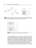
Figure
8.1 (a) A three-node network. (b) Nodes A-B and B-C are interconnected by
WDM links. All wavelengths are dropped and added at node B. (c) Half the wavelengths
pass through optically at node B, reducing the number of router ports at node B.
+ 50 Gb/s (traffic from A-C that must use link A-B) = 100 Gb/s. Similarly,
the traffic flowing on link B-C is also 100 Gb/s. Thus the 10 wavelengths on
each of the links A-B and B-C are sufficient to carry this traffic. In this case,
we use 10 router ports at node A, 20 router ports at node B, and 10 router
ports at node C, for a total of 40 router ports. At the optical layer, nodes A
and C have OLTs, whereas node B has a pair of OLTs that terminate all the
wavelengths passing through node B. This is illustrated in Figure 8.1(b).
2. With optical add/drop: In the second design, we set up only five lightpaths
each on the routes A-B, B-C, and A-C. The five lightpaths on the route A-C
pass through the node B within the optical layer, without being converted to
an electrical signal. This design requires only 10 router ports at each of the
three nodes, A, B, and C, for a total of 30 router ports, compared to 40 router
ports in the design without optical add/drop. However, this design requires
node B to have an OADM node that is capable of adding and dropping 10
of the 20 lightpaths that terminate at the router at node B, while passing the
other 10 lightpaths through. This is illustrated in Figure 8.1(c).
Thus, in the design with optical add/drop capability, we can trade off the
number of IP router ports at node B (10 versus 20) for optical add/drop capability
at the same node. In general, as we will see later, the trade-off is between the
WDM Network Design 439
cost of the higher-layer equipment (IP router ports) and the cost of the optical
layer equipment (OADMs, or increased number of wavelengths as we will see
in other examples later). Both designs are perfectly valid and will do the job
as far as the user is concerned. The choice between them will be made based
on the cost trade-off between the optical and higher-layer equipment. In this
example, providing optical add/drop capability requires an OADM at node B
instead of two OLTs. The cost of doing this is cheaper in many scenarios today
than providing additional 10 Gb/s IP router ports. This situation is likely to
prevail over the long run as well fundamentally because passing a wavelength
through is a much simpler operation than routing all the packets that have been
transmitted on a wavelength at the IP layer.
Note that in this example the transponder costs are bundled with the IP router
port costs. Increasingly, routers are being equipped with optical interfaces with
wavelengths on the ITU grid, so that no additional transponders are required.
Thus, strictly speaking, in this example, we are comparing the cost of IP layer
terminations versus keeping things optical.
In the same example, if the amount of passthrough traffic at node B was a small
fraction of a wavelength, an entire wavelength with a capacity of 10 Gb/s would have
to be used for the passthrough traffic if we used a design with optical passthrough.
At the same time, a design without optical passthrough may be able to handle the
passthrough traffic without an increase in the number of IP router ports. This would
lead us to prefer to handle the passthrough packets using the IP router at node B.
We will study this effect further in the next section in the context of rings.
From the point of view of the IP routers, the topology of the network when all the
wavelengths are terminated at node B is shown in Figure 8.2(a). This is the topology
seen by the IP layer packet-routing algorithm, such as OSPE This is a linear topology
with 10 parallel links between nodes A and B, and 10 parallel links between nodes B
and C. In the optical add/drop case, the topology of the network seen by IP routers is
a completely connected mesh with 5 parallel links between each of the three pairs of
nodes, as shown in Figure 8.2(b). Note that both topologies are capable of meeting
the traffic needs at the IP layer, which calls for 50 Gb/s of capacity between each pair
of routers.
The topology seen by the IP routers, or the SONET/SDH muxes, is the topology
of the lightpaths provided by the optical layer, and hence we will call it the
lightpath
topology,
It is often called the
logical
or
virtual
topology, but we will not employ
this terminology. In the same vein, the fiber topology upon which the lightpaths are
created is called the
physical topology,
but we will not use this terminology either.
We can view the general problem of designing wavelength-routing networks as
follows. The fiber topology and the traffic requirements (traffic matrix) are specified.