Optical Networks: A Practical Perspective - Part 54 docx
Bạn đang xem bản rút gọn của tài liệu. Xem và tải ngay bản đầy đủ của tài liệu tại đây (694.54 KB, 10 trang )
500 CONTROL AND MANAGEMENT
9.1.3
as transponders, amplifiers, multiplexers, and so on. With respect to this, there may
be an object class called
rack,
which has as one of its attributes another object class
called
shelf.
Multiple types of shelves may be represented in the form of inherited
object classes from the parent object
shelf.
For example, there may be a common
equipment shelf and a transponder shelf, which are inherited from the generic shelf
object.
A shelf object has as one of its attributes another object called
slot.
Each line card
object is associated with a slot. Multiple types of line cards may be represented in the
form of inherited object classes from the parent object
line card.
For example, the
transponder shelf may house multiple transponder types (say, one to handle SONET
signals and another to handle Gigabit Ethernet signals). The common equipment
shelf may house multiple types of cards, such as amplifier cards, processor cards,
and power supply cards.
Each object has a variety of attributes associated with it, including the set of
parameters that can be set by the management system and the set of parameters that
can be monitored by the management system. As an example, each line card object
normally has a state attribute associated with it, which is one of
in service, out of
service,
or
fault,
and there are detailed behaviors governing transitions between these
states.
Another example that is part of a typical information model is the concept of
connection trails,
which are used to model lightpaths. Again multiple types of trails
may be defined, and each trail has a variety of associated attributes, including ones
that can be configured as well as others that can be used to monitor the trail's
performance.
Management Protocols
Most network management systems use a master-slave sort of relationship between a
manager and the agents managed by the manager. The manager queries the agent to
obtain the status of parameters in the network element (called the
get
operation). For
example, the manager may query the agent periodically for performance monitoring
information. The manager can also change the values of variables in the network
element (called the
set
operation) and uses this method to effect changes within the
network element. For example, the manager may use this method to change the
configuration of the switches inside a network element such as an OXC. In addition
to these methods, it is necessary for the agent sometimes to initiate a message to
its manager. This is essential if the agent detects problems in the network element
and wants to alert its manager. The agent then sends a
notification
message to its
9.1 Network Management Functions
501
manager. Notifications also take the form of
alarms
if the condition is serious and
are sometimes called
traps.
There are multiple standards relating to network management and perhaps thou-
sands of acronyms describing them. Here is a brief summary. In most cases, the phys-
ical management interface to the network element is usually through an Ethernet or
RS-232 serial interface.
The Internet world uses a management framework based on the
simple network
management protocol
(SNMP). SNMP is an application protocol that runs over a
standard Internet Protocol stack. The manager communicates with the agents using
SNMP. The information model in SNMP is called a
management information base
(MIB).
In North America, the carrier world has been using for a few decades a simple
textual (or ASCII) command and control language called
Transaction Language-1
(TL-1). TL-1 was invented in the days when the primary means of managing net-
work elements was through a simple terminal interface using textual command sets.
However, it is still widely used today and will probably remain for a while, as many
of the existing legacy management systems still mainly support only TL-1.
Over the past decade, there has been a huge effort to standardize a management
framework for the carrier world called the
telecommunications management net-
work
(TMN). TMN defined a hierarchy of management systems and object-oriented
ways to model the information to be managed, and also specified protocols for com-
municating between managers and their agents. The protocol is called the
common
management information protocol
(CMIP), which usually runs over an
open systems
interconnection
(OSI) protocol stack; the associated management interface is called
a Q3
interface. Adaptations have also been defined for running CMIP over the more
commonly used TCP/IP protocol stack. The specific object model is based on a stan-
dard called
guidelines for description of managed objects
(GDMO). The first two
concepts of TMN, namely, the hierarchical management view and the object-oriented
way of modeling information, are widely used today, but the specific protocols, inter-
faces, and object models defined in TMN have not yet been widely adopted, mostly
because of the perceived complexity of the entire system.
There is currently a significant effort under way to migrate toward a model where
network elements from different vendors come with their own element management
systems, and a common interface is specified between these element management
systems and a centralized network management system. This interface is based on
the
common object request broker
(CORBA) model. CORBA is a software indus-
try standard developed to allow diverse systems to exchange and jointly process
information and communicate with each other.
502
CONTROL AND MANAGEMENT
9.2
Optical Layer Services and Interfacing
The optical layer provides lightpaths to other layers such as the SONET, IP, or ATM
layers. In this context, the optical layer can be viewed as a
server layer, and the higher
layer that makes use of the services provided by the optical layer as the
client layer.
From this perspective, we need to specify clearly the service interface between the
optical layer and its client layers. The key attributes of such a managed lightpath
service are the following:
9 Lightpaths need to be set up and taken down as required by the client layer and
as required for network maintenance.
9 Lightpath bandwidths need to be negotiated between the client layer and the
optical layer. Typically the client layer specifies the amount of bandwidth needed
on the lightpath.
9 An adaptation function may be required at the input and output of the optical
network to convert client signals to signals that are compatible with the optical
layer. This function is typically provided by transponders, as we discussed in
Section 7.1. The specific range of signal types, including bit rates and protocols
supported, need to be established between the client and the optical layer.
9 Lightpaths need to provide a guaranteed level of performance, typically specified
by the bit error rate (typical requirements are 10 -12 or less). Adequate perfor-
mance management needs to be in place inside the network to ensure this.
9 Multiple levels of protection may need to be supported, as we will see in Chap-
ter 10, for example, protected, unprotected, and protect on a best-effort basis,
in addition to being able to carry low-priority data on the protection bandwidth
in the network. In addition, restoration time requirements may also vary by
application.
9 Lightpaths may be unidirectional or bidirectional. Almost all lightpaths today are
bidirectional. However, if more bandwidth is desired in one direction compared
to the other, it may be desirable to support unidirectional lightpaths.
9 A multicasting, or a
drop-and-continue, function may need to be supported. Mul-
ticasting is useful to support distribution of video or conferencing information.
In a drop-and-continue situation, a signal passing through a node is dropped
locally, but a copy of it is also transmitted downstream to the next node. We will
see in Chapter 10 that the drop-and-continue function is particularly useful for
network survivability when multiple rings are interconnected.
9 Jitter requirements exist, particularly for SONET/SDH connections. In order to
meet these requirements, 3R regeneration may be needed in the network. Using
9.2 Optical Layer Services and Interfacing 503
2R regeneration in the network increases the jitter, which may not be acceptable
for some signals. We discussed 3R and 2R in the context of transparency in
Section 1.5.
9 There may be requirements on the maximum delay for some types of traffic,
notably ESCON. In ESCON, the throughput of the protocol goes down as the
propagation delay increases. This causes ESCON devices to place restrictions
on the maximum allowed propagation delay (or equivalent link length) between
them. This will need to be accounted for while designing the lightpaths.
9 Extensive fault management needs to be supported so that root-cause alarms
can be reported and adequate isolation of faults can be performed in the net-
work. This is important because a single failure can trigger multiple alarms. The
root-cause alarm reports the actual failure, and we need to suppress the remain-
ing alarms. Not only are they undesirable from a management perspective, but
they may also result in multiple entities in the network reacting to a single failure,
which cannot be allowed. We will look at examples of this later.
Enabling the delivery of these services requires a control and management inter-
face between the optical layer and the client layer. This interface allows the client to
specify the set of lightpaths that are to be set up or taken down and set the service
parameters associated with those lightpaths, and enables the optical layer to provide
performance and fault management information to the client layer. This interface can
take on one of two facets. The simple interface used today is through the manage-
ment system. A separate management system communicates with the optical layer
EMS, and the EMS in turn then manages the optical layer.
The present method of operation works fine as long as lightpaths are set up fairly
infrequently and remain nailed down for long periods of time. It is quite possible that,
in the future, lightpaths are provisioned and taken down more dynamically in large
networks. In such a scenario, it would make sense to specify a
signaling
interface
between the optical layer and the client layer. For instance, an IP router could signal
to an associated optical crossconnect to set up and take down lightpaths and specify
their levels of protection through such an interface. Different philosophies exist as to
whether such an interface is desirable or not. Some carriers are of the opinion that
they should decouple optical layer management from its client layers and plan and
operate the optical network separately. This approach makes sense if the optical layer
is to serve multiple types of client layers and allows them to decouple its management
from a specific client layer. Others would like tight coupling between the client and
optical layers. This makes sense if the optical layer primarily serves a single client
layer, and also if there is a need to set up and take down connections rapidly as we
discussed above. We will discuss this issue further in Section 9.6.
504 CONTROL AND MANAGEMENT
Figure 9.2 Layers within the optical layer, showing the optical channel-path (OCh-P)
layer, optical channel-section layer (OCh-S), optical multiplex section (OMS) layer, and
the optical transmission section (OTS) layer.
9.3
Layers within the Optical Layer
The optical layer is a complicated entity performing several functions, such as mul-
tiplexing wavelengths, switching and routing wavelengths, and monitoring network
performance at various levels in the network. In order to help delineate management
functions and in order to provide suitable boundaries between different equipment
types, it is useful to further subdivide the optical layer into several sublayers. The In-
ternational Telecommunications Union (ITU) has identified three such layers within
the optical layer, as shown in Figure 9.2. At the top is the
optical channel
(OCh)
layer. This layer takes care of end-to-end routing of the lightpaths. We have been us-
ing the term
lightpath
to denote an optical connection. More precisely, a lightpath is
an optical channel trail between two nodes that carries an entire wavelength's worth
of traffic. A lightpath traverses many links in the network, wherein it is multiplexed
with many other wavelengths carrying other lightpaths. It may also get regenerated
along the way. Note that we do not include any electronic time division multiplexing
functions in the optical layer. This is a higher-layer (for example SONET/SDH) func-
tion. So a 10 Gb/s connection between two nodes that is carried through without
any electronic multiplexing/demultiplexing would be considered a lightpath.
Each link between OLTs or OADMs represents an
optical multiplex section
(OMS) carrying multiple wavelengths. Each OMS in turn consists of several link
segments, each segment being the portion of the link between two optical amplifier
stages. Each of these portions is an
optical transmission section
(OTS). The OTS
9.4 Multivendor Interoperability 505
consists of the OMS along with an additional optical supervisory channel (OSC),
which we will study in Section 9.5.7.
The optical channel layer itself is further subdivided into multiple sublayers. ITU
G.709 describes these sublayers. To keep the discussion simple, we will use some
terms that differ slightly from the ITU definitions. An
optical channel-transparent
section
(OCh-TS) represents the section of a lightpath within an all-optical subnet-
work. Within this section, a lightpath is carried optically without any conversion into
the electrical domain. At the boundary of an OCh-TS, a lightpath is regenerated. Just
above the OCh-TS is the
optical channel-section
(OCh-S). This layer adds some over-
heads to the lightpath, such as forward error correction (FEC), to condition the signal
for transport over an all-optical subnet. Finally, the
optical channel-path
(OCh-P)
represents the end-to-end transport of a lightpath across multiple regenerators in the
path.
In principle, once the interfaces between the different layers are defined, it is
possible for vendors to provide standardized equipment ranging from just optical
amplifiers to WDM links to entire WDM networks. Equally importantly, the layers
help us break down the management functions necessary in the network, as we will
see in this chapter and in Chapter 10. For example, dropping and adding wavelengths
is a function performed at the optical channel layer. Monitoring optical power on
each wavelength also belongs to this layer, but monitoring total power belongs either
to the OTS layer or the OMS layer, depending on whether the optical supervisory
channel is included or not.
The preceding definition of an optical layer does not include optical networks
that may be able to provide more sophisticated packet-switched services, such as
virtual circuits or datagrams. We will study photonic packet-switched networks
in Chapter 12 that can potentially provide such services; however, these types of
networks are several years away from commercial realization.
9.4
Multivendor Interoperability
Service providers like to deploy equipment from multiple vendors that operate to-
gether in a single network. This is desirable to reduce the dependence on any single
vendor as well as to drive down costs and is one of the driving factors behind net-
work standards. For instance, without standards, we would have to have special
interoperability between every pair of vendors, rather than having to deal with a sin-
gle standardized interface to which all vendors conform. Another important effect
of standards is that they allow operations personnel to get trained on a single type
of equipment and then become capable of managing that type of equipment from a
506 CONTROL AND MANAGEMENT
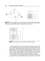
Figure
9.3 Interoperability between WDM systems from different vendors, show-
ing all-optical subnets from different vendors interconnected through transponder/
regenerators.
variety of vendors, in contrast to being trained separately to deal with each vendor's
equipment.
However, interoperability between WDM equipment from different vendors is
easier said than done. The SONET standards were established in the late 1980s, and
only recently have we been able to achieve interoperability between equipment from
different vendors. In the case of WDM, achieving interoperability at the optical level
is made particularly difficult by the fact that the interface is a fairly complex analog
interface, rather than a simple digital interface. The set of parameters that we would
need to standardize to achieve interoperability include optical wavelength; optical
power; signal-to-noise ratio; bit rate; and the supervisory channel wavelength, bit
rate, and its contents. Different vendors use significantly different parameters in their
link design and make different compromises among the various impairments that we
studied in Chapter 5. For example, vendor A might choose to use directly modulated
lasers and dispersion compensation inside the network to eliminate dispersion. Ven-
dor B instead might choose to use externally modulated lasers and avoid dispersion
compensation inside the network. This would make it difficult to have vendor A's
equipment and vendor B's equipment on opposite sides of the same WDM link. Even
if some interoperability can be achieved, it is quite difficult to locate and isolate faults
in such an environment.
Rather than trying to solve this complex problem, the practical solution to-
ward interoperability is to use regenerators or transponders to interconnect disparate
all-optical subnetworks, as shown in Figure 9.3. While this approach may result in
higher equipment costs, it provides clear-cut boundaries between all-optical subnets,
9.5 Performance and Fault Management 507
making it easier to locate and identify faults. Each all-optical subnet would include
equipment from a single vendor. For example, a subnet could simply be a WDM
link with some intermediate add/drops. So a service provider could deploy vendor
A's equipment on one link and vendor B's equipment on another link and have them
interoperate through transponders. The interface between the transponders would
be either SONET/SDH or the digital wrapper, which we will study in Section 9.5.7.
Using the digital wrapper allows the service provider to manage the entire network
effectively.
The standards bodies initially started with the goal of establishing optical inter-
operability and are still pursuing this (ITU G.959, Telcordia GR-2918), although it
will be a while before this comes to fruition in a practical network. Meanwhile there
is a consensus building around the digital wrapper standard (ITU G.709).
In addition to accomplishing interoperability at the data level, we also need to
have interoperability as far as the control and signaling protocols are concerned,
particularly if we are using distributed methods discussed in Section 9.6.2. This is
a goal that appears to be accomplishable, given that similar functions have been
standardized for other networks in the past.
9.5
Performance and Fault Management
As we stated earlier, the goal of performance management is to enable service
providers to provide guaranteed quality of service to the users of their network.
This usually requires monitoring of the performance parameters for all the connec-
tions supported in the network and taking any actions necessary to ensure that the
desired performance goals are met. Performance management is closely tied in to
fault management. Fault management involves detecting problems in the network
and alerting the management systems appropriately through alarms. If a certain pa-
rameter is being monitored and its value falls outside its preset range, the network
equipment generates an alarm. For example, we may monitor the power levels of an
incoming signal and declare a loss-of-signal (LOS) alarm if we see the power level
drop below a certain threshold. In other cases, alarms could be triggered by outright
failures, such as the failure of a line card or other components in the system.
Fault management also includes restoring service in the event of failures, a subject
that we will cover in detail in Chapter 10. This function is considered an autonomous
network control function because it is typically a distributed application without net-
work managment intervention (except for configuring various protection parameters
up front, reporting events, and performing maintenance operations).
508 CONTROL AND MANAGEMENT
9.5.1
The Impact of Transparency
The lightpaths provided by the optical layer need to be managed just like SONET
and SDH connections are managed. To a large extent how much management
can be provided depends on the level of transparency provided by the optical
layer. As we have seen in Chapter 1, different levels of transparency are possi-
ble, based on the range of signals, bit rates, and protocols that can be carried on a
lightpath.
In a purely transparent network, a lightpath will be capable of carrying ana-
log and digital signals with arbitrary bit rates and protocol formats. This is the
utopian vision of optical networking and would allow service providers to offer a
range of services without any constraints and provide future-proofing in case the
service mix changes over time or when new services are added. However, such
a network is very difficult to engineer and manage. It is difficult to engineer be-
cause the various physical layer impairments that must be taken into account in
the network design are critically dependent on the type of signal (analog versus
digital) and the bit rate. It is difficult to manage because the management sys-
tem may have no prior knowledge of the protocols or bit rates being used in
the network. Therefore, it is not possible to access overhead bits in the transmit-
ted data to obtain performance-related measures. This makes it difficult to mon-
itor the bit error rate. Other parameters such as optical power levels and optical
signal-to-noise ratios can be measured. Most systems today only measure optical
power levels. However, small, portable optical spectrum analyzers are now becom-
ing available to measure the signal-to-noise ratio, making it practical to incorpo-
rate this measurement in newer systems. However, the acceptable values for these
parameters depend on the type of signal. Unless the management system is told
what type of signal is being carried on a lightpath, it will not be able to determine
whether the measured power levels and signal-to-noise ratios fall within acceptable
limits.
At the other exteme, we could design a network that carries data at a fixed bit
rate (say, 2.5 Gb/s or 10 Gb/s) and of a particular format (say, SONET/SDH only).
Such a network would be very cost-effective to build and manage. However, it does
not offer service providers the flexibility they need to deliver a wide variety of services
using a single network infrastructure and is not future-proof at all.
Most optical networks deployed today fall somewhere in between these two
extremes. The network is designed to handle digital data at arbitrary bit rates up to
a certain specified maximum (say, 10 Gb/s) and a variety of protocol formats such
as SONET/SDH, IP, ATM, Gigabit Ethernet, and ESCON. These networks make use
of a number of unique techniques to provide management functions, as we will see
next.
9.5 Performance and Fault Management 509
9.5.2
BER Measurement
The bit error rate (BER) is the key performance attribute associated with a lightpath.
The BER can be detected only when the signal is available in the electrical domain,
typically at regenerator or transponder locations. As we saw in Chapter 6, framing
protocols used in SONET and SDH include overhead bytes. Part of this overhead
consists of parity check bytes by which the BER can be computed. This provides
a direct measure of the BER. Similarly, the digital wrapper overhead developed
specifically for the optical layer also allows the BER to be measured. We will study
the digital wrapper in Section 9.5.7. As long as the client signal data is encapsulated
using the SONET/SDH or digital wrapper overhead, we can measure the BER and
guarantee the performance within the optical layer.
Given the complexity of optical physical layer designs, it is difficult to estimate
the BER accurately based on indirect measurements of parameters such as the optical
signal power or the optical signal-to-noise ratio. These parameters may be used to
provide some measure of signal quality and may be used as triggers for events such
as maintenance or possibly protection switching (which could be based, for example,
on loss of power and signal detection) but not to measure BER.
9.5.3
Optical Trace
Lightpaths pass through multiple nodes and through multiple cards within the equip-
ment deployed at each node. It is desirable to have a unique identifier associated with
each lightpath. For example, this identifier may include the IP address of the origi-
nating network element along with the actual identity of the transponder card within
that network element where the lightpath terminates. This identifier is called an
op-
tical path trace.
The trace enables the management system to identify, verify, and
manage the connectivity of a lightpath. In addition it provides the ability to perform
fault isolation in the event that incorrect connections are made.
A trace can be used in different layers within the optical layer. For instance,
a lightpath passes through multiple nodes and potentially gets regenerated along
the way. We can verify the end-to-end connectivity of a lightpath using an
opti-
cal channel-path trace.
This trace is inserted at the beginning of the lightpath and
monitored at various locations along the path of the lightpath. In order to localize
and verify connectivity between regenerator locations, we make use of an additional
identifier called the
optical channel-section trace,
which is associated between each
adjacent pair of regeneration points of the lightpath. Within an all-optical subnet, we
can use a
optical channel-transparent section trace.
The latter two traces are inserted
and removed at regenerator locations in the network. We will look at different ways
of carrying the trace information in Section 9.5.7.