Optical Networks: A Practical Perspective - Part 58 pdf
Bạn đang xem bản rút gọn của tài liệu. Xem và tải ngay bản đầy đủ của tài liệu tại đây (877.31 KB, 10 trang )
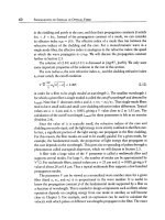
540
NETWORK SURVIVABILITY
SONET/SDH. A ring is the simplest topology offering an alternate route around a
failure. In the optical layer, many protection schemes have been designed to operate
over true mesh topologies.
Protection may be
dedicated
or
shared.
In dedicated protection, each working
connection is assigned its own dedicated bandwidth in the network over which it
can be rerouted in case of a failure. In shared protection, we make use of the fact
that not all working connections in the network fail simultaneously (for example, if
they are in different parts of the network). Therefore, by careful design, we can make
multiple working connections share protection bandwidth among themselves. This
helps reduce the amount of bandwidth needed in the network for protection. Another
advantage of shared protection is that the protection bandwidth is available to carry
low-priority traffic under normal conditions. This low-priority traffic is discarded in
the event of a failure when the bandwidth is needed to protect a connection.
Protection schemes can either be
revertive
or
nonrevertive.
In both schemes, if
a failure occurs, traffic is switched from the working path to the protect path. In
a nonrevertive scheme, the traffic remains on the protect path until it is manually
switched back onto the original working path, usually by a user through the network
management system. In a revertive scheme, once the working path is repaired, the
traffic is automatically switched back from the protect path onto the working path.
Reversion allows the network to return to its original state once the failure is restored.
Dedicated protection schemes may be revertive or nonrevertive; however, shared
protection schemes are usually revertive. Since multiple working connections share
a common protection bandwidth, the protection bandwidth must be freed up as
soon as possible after the original failure has been repaired, so that it can be used to
protect other connections in the event of another failure occurring.
To confuse terminology further, the protection switching can be
unidirectional
or
bidirectional.
This is not to be confused with unidirectional transmission or bidi-
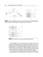
rectional transmission over a fiber. Figure 10.1 illustrates the two schemes for the
case where two fiber pairs are used on the point-to-point link, with each fiber carry-
ing traffic in one direction (unidirectional transmission). In unidirectional protection
switching, each direction of traffic is handled independent of the other. Thus in
the event of a single fiber cut, only one direction of traffic is switched over to the
protection fiber and the other direction remains on the original working fiber. In
bidirectional switching, both directions are switched over to the protection fibers.
For the case where bidirectional transmission is used, the switching mostly becomes
bidirectional by default because both directions of traffic are lost when a fiber is cut
(both directions may not be lost if there is an equipment failure, rather than a fiber
cut).
Unidirectional protection switching is used in conjuction with dedicated protec-
tion schemes since it can be implemented very easily by switching the traffic at the
10.1 Basic Concepts
541
Figure
10.1 Unidirectional and bidirectional protection switching. (a) The link is shown
under normal operation. (b) Unidirectional protection switching. After a unidirectional
fiber cut, only the affected direction of traffic is switched over to the protection fiber.
(c) Bidirectional protection switching. After a undirectional fiber cut, both directions of
traffic are switched over to the protection fibers.
receiving end from the working to the protect path, without requiring a signaling
protocol between the receiver and the transmitter. For example, in Figure 10.1, if
a fiber carrying traffic from left to right is cut, without affecting the fiber carrying
traffic from right to left, the transmitter on the left is not aware that there has been
a failure. In the case of unidirectional dedicated protection, if traffic is transmitted
simultaneously on the working and protect paths, the receiver at the end of the paths
simply selects the better of the two arriving signals. However, if bidirectional switch-
ing is required, the receiver needs to inform the transmitter that there has been a cut.
This requires a signaling protocol, called an
automatic protection-switching
(APS)
protocol.
542 NETWORK SURVIVABILITY
A simple APS protocol works as follows: if a receiver in a node detects a fiber
cut, it turns off its transmitter on the working fiber and then switches over to the
protection fiber to transmit traffic. The receiver at the other node then also detects the
loss of signal on the working fiber and then switches its traffic over to the protection
fiber. Actual APS protocols used in SONET and optical networks are quite a bit more
complicated because they have to deal with many different possible scenarios than
the one described here.
In a bidirectional communication system, where traffic is transmitted in both
directions over a single fiber, a fiber cut will be detected by both the source and
the destination. While no APS protocol is required to deal with fiber cuts, an APS
protocol will still be needed to deal with unidirectional equipment failures and to
support other maintenance functions.
In the case of shared protection schemes, an APS protocol is required to coordi-
nate access to the shared protection bandwidth. Therefore most shared protection
schemes use bidirectional protection switching because it is easier to control and
manage in a more complex network than unidirectional switching.
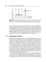
There is also the question of how and where the traffic is rerouted in the event
of a failure. Here we distinguish between
path
switching,
span
switching, and
ring
switching. Figure 10.2 illustrates these concepts. In path switching (Figure 10.2(b)),
the connection is rerouted end to end from its source to its destination along an alter-
nate path. In span switching (Figure 10.2(c)), the connection is rerouted on a spare
link between the nodes adjacent to the failure. In ring switching (Figure 10.2(d)), the
connection is rerouted on a ring between the nodes adjacent to the failure.
Finally, different protection schemes operate at different layers in the network
(for example, SONET/SDH, ATM, MPLS, IP) and at different sublayers within a
layer. For example, there are schemes that protect one connection at a time, as well
as schemes that protect all connections on a failed fiber together. In SONET/SDH
networks, the former schemes operate at the path layer, and the latter schemes operate
at the line (multiplex section in SDH) layer. In many cases, path layer schemes operate
end to end, rerouting traffic along an alternate path all the way from the source to
the destination. In contrast, line layer schemes are almost all localized~that is, they
reroute traffic around the failed link. Similarly, in the optical layer, we have schemes
operating either at the optical channel layer or the optical multiplex section layer.
10.2
Protection in SONET/SDH
A major accomplishment of SONET and SDH network deployment was to provide
a significant improvement in the availability and reliability of the overall network.
This was done through the use of an extensive set of protection techniques. Similar
10.2 Protection in SONET/SDH
543
Figure
10.2 Path, span, and ring switching. (a) Working path for the connection under
normal operation. (b) Path switching, where the connection is rerouted end to end on
an alternate path. (c) Span switching, where the connection is rerouted on a spare link
between the nodes adjacent to the failure. (d) Ring switching, where the connection is
rerouted on a ring between the nodes adjacent to the failure.
schemes are used in both SONET and SDH, but their nomenclature is different. We
will specify both nomenclatures but use the SONET nomenclature for the most part.
A taxonomy of the different protection schemes is given in Table 10.1. We will
start by describing the different types of protection mechanisms that are used for
simple point-to-point links, and then discuss how these can be applied for networks.
Each protection scheme can be associated with a specific layer in the network. As
we saw in Chapter 6, the SONET layer includes a
path
layer and a
line
layer.
Both path layer and line layer protection schemes are used in practice. Equivalently,
SDH networks use both
channel
layer and
multiplex section
(MS) layer protection
schemes. A path layer protection scheme operates on individual paths or connections
in the network. For example, in an OC-48 (2.5 Gb/s) ring supporting STS-1 (51 Mb/s)
connections, a path layer scheme would treat each STS-1 connection independently
544 NETWORK SURVIVABILITY
Table 10.1 A summary of protection schemes in SONET and SDH. N denotes the number of
working interfaces that share a single protection interface. The schemes operate either in the path
layer or in the SONET line layer/SDH multiplex section (MS) layer. Path layer ring schemes include
unidirectional path-switched ring (UPSR) or 1 + 1 subnetwork connection protection (SNCP). Line
layer ring schemes include bidirectional line-switched ring (BLSR) or, equivalently, multiplexed
section-shared protection ring (MS-SPRing).
Protection Scheme
SONET Term 1 + 1 I:N UPSR BLSR
SDH Term 1 + 1 I:N
SNCP MS-SPRing
Type Dedicated Shared Dedicated Dedicated Shared
Topology Point-point Point-point Ring Ring/mesh Ring
Layer Line/MS Line/MS Path/- -/path Line/MS
and switch them independently of each other. A line layer scheme on the other hand,
operates on the entire set of connections at once and generally does not distinguish
between the different connections that are part of the aggregate signal. In the former
example, a line layer protection scheme in an OC-48 ring would switch all the
connections within the OC-48 together. (There are some exceptions to this statement.
The bidirectional line-switched rings (BLSRs) that we will study later do allow bits
to be set for each connection. In the event of a failure, only those connections that
are specified are switched. This is needed to ensure that some connections can be
left unprotected if so desired, and also to handle node failures, as we will see in
Section 10.2.4.)
10.2.1
Point-to-Point Links
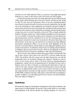
Two fundamental types of protection mechanisms are used in point-to-point links:
1 + 1 protection and 1:1 or, more generally, 1 :N protection, as shown in Figure 10.3.
Both operate in the line or multiplex section layer.
In 1 + 1 protection, traffic is transmitted simultaneously on two separate fibers
(usually over disjoint routes) from the source to the destination. Assuming unidirec-
tional protection switching, the destination simply selects one of the two fibers for
reception. If that fiber is cut, the destination simply switches over to the other fiber
and continues to receive data. This form of protection is very fast and requires no
signaling protocol between the two ends. Note that since connections are usually
full duplex, there is actually a pair of fibers between the two nodes, say, node A and
10.2 Protection in SONET/SDH
545
Figure
10.3 Different types of protection techniques for point-to-point links: (a) 1 + 1
protection, where the signal is simultaneously transmitted over two paths; (b) 1:1 pro-
tection, where the signal is transmitted over a working path under normal conditions
but switched to a protect path after a failure; and (c) I:N protection, which is a more
generalized form of 1:1 protection, where N working paths share a single protection path.
546 NETWORK SURVIVABILITY
node B for the working traffic. One fiber carries traffic from A to B, and the other
carries traffic from B to A. Likewise there is another pair of fibers for protection
traffic. Node A's receiver and node B's receiver can make the switching decisions
independently.
In 1:1 protection, there are still two fibers from the source to the destination.
However, traffic is transmitted over only one fiber at a time, say, the working fiber. If
that fiber is cut, the source and destination both switch over to the other protection
fiber. As we discussed earlier, an APS protocol is required for signaling between the
source and destination. For this reason, 1:1 protection is not as quick as unidi-
rectional 1 + 1 protection in restoring traffic because of the added communication
overhead involved. However, it offers two main advantages over 1 + 1 protection.
The first is that under normal operation, the protection fiber is unused. Therefore,
it can be used to transmit lower-priority traffic. This lower-priority traffic must be
discarded if the working fiber is cut. SONET and SDH equipment in the field does
provide support for this lower-priority or
extra traffic.
This capability is not widely
used today, but carriers in the past have used this capability on occasion to carry
"lower-priority" data traffic or even voice traffic, when their networks are temporar-
ily over capacity. This is likely to change in the future with the advent of data services,
as we shall see in Section 10.4. Best-effort data services, in particular, can use this
capability.
Another advantage is that the 1:1 protection can be extended so as to share a
single protection fiber among many working fibers. In a more general 1 :N protection
scheme, N working fibers share a single protection fiber. This arrangement can handle
the failure of any single working fiber. Note that in the event of multiple failures,
the APS protocol must ensure that only traffic on one of the failed fibers is switched
over to the protection fiber.
In the previous discussion we talked about how the protection is done,
but skimmed over what the triggers are for initiating protection switching. In
SONET/SDH, the incoming signal is continously monitored. Protection switching
is initiated if a signal fail or a signal degrade condition is detected on the line. A
signal fail represents a hard failure and is detected typically as a loss of signal or as a
loss of the SONET/SDH frame. Out of the 60 ms allowed for restoration, detecting
the failure and initiating protection switching must be performed within 10 ms.
10.2.2
Self-Healing Rings
Ring networks have become very popular in the carrier world as well as in enterprise
networks. A ring is the simplest topology that is
2-connected,
that is, provides two
10.2 Protection in SONET/SDH 547
separate paths between any pair of nodes that do not have any nodes or links in
common except the source and destination nodes. This allows a ring network to be
resilient to failures. Rings are also efficient from a fiber layout perspectivemmultiple
sites can be interconnected with a single physical ring. In contrast, a hubbed ap-
proach would require fibers to be laid between each site and a hub node, and would
require two disjoint routes between each site and the hub, which is a more expensive
proposition.
Much of the carrier infrastructure today uses
SONET/SDH
rings. These rings
are called
sel~-healing
since they incorporate protection mechanisms that automati-
cally detect failures and reroute traffic away from failed links and nodes onto other
routes rapidly. The rings are implemented using
SONET/SDH
add/drop multiplex-
ers (ADMs), which we studied in Section 6.1. These ADMs selectively drop and add
traffic from/to the ring as well as protect the traffic against failures.
The different types of ring architectures differ in two aspects: in the direction-
ality of traffic and in the protection mechanisms used. A
unidirectional
ring carries
working traffic in only one direction of the ring (say, clockwise), as shown in Fig-
ure 10.4. Working traffic from node A to node B is carried clockwise along the ring,
and working traffic from B to A is also carried clockwise, on a different set of links
in the ring. A
bidirectional
ring carries working traffic in both directions. Figure 10.5
shows a four-fiber bidirectional ring. Working traffic from A to B is carried clockwise,
and working traffic from B to A is carried counterclockwise along the ring. Note
that in both unidirectional and bidirectional
SONETISDH
rings, all connections are
bidirectional and use up the same amount of bandwidth in both directions. The two
directions of a connection are routed differently based on the type of ring, as we
discussed earlier.
The
SONET/SDH
standards dictate that in
SONET/SDH
rings, service must be
restored within 60 ms after a failure. This time includes several components: the
time needed to detect the failure, for which 10 ms is allocated; the time needed to
signal to other nodes in the network (if needed), including the propagation delays;
the actual switching time; and the time to reacquire the frame synchronization after
the switch-over has occurred.
Three ring architectures have been widely deployed: two-fiber unidirectional
path-switched rings (UPSR), four-fiber bidirectional line-switched rings (BLSR/4),
and two-fiber bidirectional line-switched rings (BLSR/2). In SDH, the 1 + 1 path
protection has been defined to operate in a more general mesh topology and is called
subnetwork connection protection (SNCP). SDH multiplex section shared protection
ring/4
(MS-SPRing/4)
and
MS-SPRing/2
are similar to BLSR/4 and BLSR/2, respec-
tively. Table 10.2 summarizes the features of the different architectures, which we
will discuss in detail in the following sections.
548 NETWORK SURVIVABILITY
Figure 10.4 A unidirectional path-switched ring (UPSR). One of the fibers is considered
the working fiber and the other the protection fiber. Traffic is transmitted simultaneously
on the working fiber in the clockwise direction and on the protection fiber in the coun-
terclockwise direction. Protection is done at the path layer.
Table 10.2 Comparison of different types of self-healing rings.
Parameter UPSR B LSR/4 B LSR/2
SNCP MS-SPRing/4 MS-SPRing/2
Fiber pairs 1 2 1
TX/RX pairs/node 2 4 2
Protection type Dedicated Shared Shared
Protection capacity = Working - Working = Working
capacity capacity capacity
Link failure Path Span/ring Ring
switch switch switch
Node failure Path Ring Ring
switch switch switch
Restoration speed Faster Slower Slower
Implementation Simple Complex Complex
10.2 Protection in SONET/SDH
549
Figure 10.5 A
four-fiber bidirectional line-switched ring (BLSR/4). The ring has two
working fibers and two protection fibers. Traffic between two nodes is transmitted nor-
mally on the shortest path between them, and either span or ring switching is used to
restore service after a failure.
10.2.3
Unidirectional Path-Switched Rings
Figure 10.4 shows a UPSR. One fiber is used as the working fiber and the other as the
protection fiber. Traffic from node A to node B is sent simultaneously on the working
fiber in the clockwise direction and on the protection fiber in the counterclockwise
direction. The protection is performed at the path layer for each connection as
follows. Node B continuously monitors both the working and protection fiber and
selects the better signal between the two for each SONET connection. Under normal
operation, suppose node B receives traffic from the working fiber. If there is a link
failure, say, of link AB, then B will switch over to the protection fiber and continue
to receive the data. Note that the switch-over is done on a connection-by-connection
basis (see Problem 10.8). Observe that this is essentially like the 1 + 1 scheme that
we studied earlier, except that it is operating at the path layer in a ring rather than
at the line layer in a point-to-point configuration.