Hardware and Computer Organization- P7 ppsx
Bạn đang xem bản rút gọn của tài liệu. Xem và tải ngay bản đầy đủ của tài liệu tại đây (598.31 KB, 30 trang )
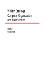
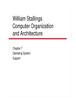
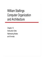
Chapter 7
162
in the data, corresponding to intentional gaps so as not to create regions of data containing non-
aligned accesses.
Also notice that when we are doing 32-bit word accesses, address bits A0 and A1 aren’t being
used. This might prompt you to ask, “If we don’t use them, what good are they?” However, we do
need them when we need to access a particular byte within the 32-bit words. A0 and A1 are often
called the byte selector address lines because that is their main function. Another point is that we
really only need byte selectors when we are writing to memory. Reading from memory is fairly
harmless, but writing changes everything. Therefore, you want to be sure that you modify only the
byte you are interested in and not the others. From a hardware designer’s perspective having byte
selectors allows you to qualify the write operation to only the byte that you are interested in.
Many processors will not explicitly have the byte selector address lines at all. Rather, they provide
signals on the status bus which are used to qualify the WRITE operations to memory. What about
storing 16-bit quantities (a short data type) in 32-bit memory locations? The same rules apply
in this case. The only valid addresses would be those addresses divisible by 2, such as 000000,
000002, 000004, and so on. In the case of 16-bit word addressing, the lowest order address bit, A0,
isn’t needed. For our 68K processor, which has a 16-bit wide data bus to memory, we can store
two bytes in each word of memory, so A0 isn’t used for word addressing and becomes the byte
selector for the processor.
Figure 7.3 shows a typi
-
cal 32-bit processor and
memory system interface.
The READ signal from the
processor and the CHIP
SELECT signals have been
omitted for clarity. The
processor has a 32-bit data
bus and a 32-bit address
bus. The memory chips
represent one page of RAM
somewhere in the address
space of the processor.
The exact page of memory
would be determined by
the design of the Address
Decoder logic block. The
RAM chips each have a
capacity of 1 Mbit and are
organized as 128K by 8.
Since we have a 32-bit wide
data bus and each RAM chip has eight data I/O lines, we need four memory chips per 128K wide
page. Chip #1 is connected to data lines D0 through D7, chip #2 is connected to data lines D8
Figure 7.3: Memory organization for a 32-bit microprocessor. Chip select
and READ signals have been omitted for clarity.
D0
D1
D2
D3
D4
D5
D6
D7
D8
D9
D10
D11
D12
D13
D14
D15
D16
D17
D18
D19
D20
D21
D22
D23
D24
D25
D26
D27
D28
D29
D30
D31
A2
A3
A4
A5
A6
A7
A8
A9
A10
A11
A12
A13
A14
A15
A16
A17
A18
A19
A20
A21
A22
A23
A24
A25
A26
A27
A28
A29
A30
A31
A0
A1
A2
A3
A4
A5
A6
A7
A8
A9
A10
A11
A12
A13
A14
A15
A16
D0
D1
D2
D3
D4
D5
D6
D7
WR
128K × 8 RAM #1
D0 – D7
A0
A1
A2
A3
A4
A5
A6
A7
A8
A9
A10
A11
A12
A13
A14
A15
A16
D0
D1
D2
D3
D4
D5
D6
D7
WR
128K × 8 RAM #2
D8 – D15
A0
A1
A2
A3
A4
A5
A6
A7
A8
A9
A10
A11
A12
A13
A14
A15
A16
D0
D1
D2
D3
D4
D5
D6
D7
WR
128K × 8 RAM #3
D16 – D23
A0
A1
A2
A3
A4
A5
A6
A7
A8
A9
A10
A11
A12
A13
A14
A15
A16
D0
D1
D2
D3
D4
D5
D6
D7
WR
128K × 8 RAM #4
D24 – D31
WE0
WE1
WE2
WE3
Address Decoder
32-bit microprocessor
Memory Organization and Assembly Language Programming
163
through D15, chip #3 is connected to data lines D6 through D23 and chip #4 is connected to data
lines D24 to D31, respectively.
The address bus from the processor contains 30 address lines, which means it is capable of address
2
30
long words (32-bit wide). The additional addressing bits needed to address the full address
space of 2
32
bytes are implicitly controlled by the processor internally and explicitly controlled
through the 4 WRITE ENABLE signals labeled
WE0 through WE3.
Address lines A2 through A18 from the processor are connected to address inputs A0 through A16
of the RAM chips, with A2 from the processor being connected to A0 on each of the 4 chips, and
so on. This may seem odd at first, but it should make sense to you after you think about it. In fact,
there is no special reason that each address line from the processor must be connected to the same
address input pin on each of the memory devices. For example, A2 from the processor could be
connected to A14 of chip #1, A3 of chip #2, A8 of chip #3 and A16 of chip #4. The same address
from the processor would clearly be addressing different byte addresses in each of the 4 memory
chips, but as long as all of the 17 address lines are from the processor are connected to all 17
address lines of the memory devices, the memory should work properly.
The upper address bits from the processor, A19 through A31 are used for the page selection pro
-
cess. These signals are routed to the address decoding logic where the appropriate
CHIP SELECT
signals are generated. These signals have been omitted from Figure 7.3. There are 13 higher order
address bits in this example. This gives us 2
13
or 8,192 pages of memory. Each page of memory
holds 128K 32-bit wide words, which works out to be 2
30
long words. In terms of addresses, each
page actually contains 512 Kbytes, so the byte address range on each page goes from byte address
(in HEX) 00000 through 7FFFF. Recall that in this memory scheme, there are 8,192 pages with
each page holding 512 Kbytes. Thus, page addresses go from 0000 through 1FFF. It may not seem
obvious to you to see how the page addresses and the offset addresses are related to reach other but
if you expand the hexadecimal addresses to binary and lay them next to each other you should see
the full 32-bit address.
Now, let’s see how the processor deals with data sizes smaller than long words. Assume that the
processor wants to read a long word from address ABCDEF64 and that this address is decoded to
be on the page of Figure 7.3. Since this address is on a 32 bit boundary, A0 and A1 = 0, and are not
used as part of the external address that goes to memory. However, if the processor wanted to do
a word access of either one of the words located at address ABCDEF64 or ABCDEF66, it would
still generate the same external address. When the data was read into the processor, the ½ of the
long word that was not needed would be discarded. Since this is a READ operation, the contents
of memory are not affected.
If the processor wanted to read any one of the 4 bytes located at byte address ABCDEF64,
ABCDEF65, ABCDEF66 or ABCDEF67, it would still perform the same read operation as before.
Again, only the byte of interest would be retained and the others would be discarded.
Now, let’s consider a write operation. In this case, we are concerned about possibly corrupting
memory, so we want to be sure that when we write a quantity smaller than a long word to memory,
we do not accidentally write more than we intend to. So, suppose that we want to write the byte
Chapter 7
164
at memory location ABCDEF65. In this case, only the WE1 signal would be asserted, so only
that byte position could be modified. Thus, to write a byte to memory, we only activate one of the
4 WRITE ENABLE signals. To write a word to memory we would active either
WE0 and WE1
together or WE2 and WE3. Finally, to write a long word, all four of the WRITE ENABLE lines
would be asserted.
What about the case of a 32-bit word stored in a 16-bit memory? In this case, the 32-bit word
can be stored on any even word boundary because the processor must always do two consecutive
memory accesses to retrieve the entire 32-bit quantity. However, most compilers will still try to
store the 32-bit words on natural boundaries (addresses divisible by 4). This is why assembly lan
-
guage programmers can often save a little space or speed up an algorithm by overriding what the
compiler does to generate code and tweaking it for greater efficiency.
Let’s get back on track. For a 32-bit processor, address bits A2 A31 are used to address the
1,073,741,824 possible long words, and A0 A1 address the four possible bytes within the long
word. This gives us a total of 4,294,967,296 addressable byte locations in a 32-bit processor. In
other words, we have a byte addressing space of 4 GB. A processor with a 16-bit wide data bus,
such as the 68K, uses address lines A1–A23 for word addressing and A0 for byte selection.
Combining all of this, you should see the problem. You could have an 8-bit byte, a 16-bit word or a
32-bit word with the same address. Isn’t this ambiguous? Yes it is. When we’re programming in a
high-level language, we depend upon the compiler to keep track of these messy details. This is one
reason why
casting one variable type to another can be so dangerous. When we are programming
in a low-level language, we depend upon the skill of the programmer to keep track of this.
Seems easy enough, but it’s not. This little fact of computer life is one of the major causes of soft
-
ware bugs. How can a simple concept be so complex? It’s not complex, it’s just ambiguous. Figure
7.4 illustrates the problem. The leftmost column of Figure 7.4 shows a string (aptly named “string”)
stored in an 8-bit memory space. Each ASCII character occupies successive memory locations.
Figure 7.4: Two methods of packing bytes into 16-bit memory words. Placing the low order byte at the
low order end of the word is called Little Endian. Placing the low order byte at the high order side of
the word is called Big Endian.
Bit
7 0
0x0000
0xFFFF
0xFFFE
S
T
R
I
N
G
7 0
ST
RI
N
G
15 8
Bi
t
0x00000
0x00001
0xFFFFE
0xFFFFF
7 0
S
T
R
I
N
G
15 8
Bi
t
0x00000
1
0x000000
0xFFFFF
F
0xFFFFF
E
Byte Addressable
memory for
a
16-bit processo
r
with a 24-bit
addressing range
MC68000
Big Endian
Byte Addressable
memory
for an
8-bit processor
with a 16-bit
addressing range
Byte Addressable
memory
for a
16-bit processo
r
with a 20-bit
addressing range
Intel 80186
Little Endian
Memory Organization and Assembly Language Programming
165
The middle column shows a 16-bit memory that is organized so that successive bytes are stored
right to left. The byte corresponding to A0 = 0 is aligned with the low order portion, DB0 . . . DB7,
of the 16-bit word and the byte corresponding to A0 = 1 is aligned with the high order portion,
DB8 DB15, of the 16-bit word. This is called Little Endian organization. The rightmost column
stores the characters as successive bytes in a left to right fashion. The byte position corresponding to
A0 = 0 is aligned with the high order portion of the 16-bit word. This is called Big Endian organiza-
tion. As an exercise, consider how the bytes are stored in Figure 7.2. Are they big or little Endian?
Motorola and Intel, chose to use different endian conventions and Pandora’s Box was opened for
the programming world. Thus, C or C++ code written for one convention would have subtle bugs
when ported to the other convention. It gets worse than that. Engineers working together on
projects misinterpret specifications if the intent is one convention and they assume the other. The
ARM architecture allows the programmer to establish which type of “endianess” will be used by
the processor at power-up. Thus, while the ARM processor can deal with either big or little endian,
it cannot dynamically switch modes once the endianess is established. Figure 7.5 shows the
difference between the two
conventions for a 32-bit word
packed with four bytes.
If you take away anything
from this text, remember this
problem because you will see
it at least once in your career
as a software developer.
Before you accuse me of beating this subject to death, let’s look at it one more time from the
hardware perspective. The whole area of memory addressing can be very confusing for novice pro
-
grammers as well as seasoned veterans. Also, there can be ambiguities introduced by architectures
and manufacturer’s terminology. So, let’s look at how Motorola handled it for the 68K and perhaps
this will help us to better understand what’s really going on, at least in the case of the Motorola
processor, even though we have already looked at the problem once before in Figure 7.3. Figure
7.6 summarizes the memory addressing scheme for the 68K processor.
The 68K processor is capable of directly addressing 16 Mbytes of memory, requiring 24 “effec
-
tive” addressing lines. Why? Because 2
24
= 16,777,216. In Figure 7.6 we see 23 address lines. The
missing address line, A0, is synthesized by two additional control signals,
LDS and UDS.
For a 16-bit wide external data bus, we would normally address bit A0 to be the byte selector.
When A0 is 0, we choose the even byte, and when A0 = 1, we choose the odd byte. The
endian-
ness of the 68K is Big Endian, so that the even byte is aligned with D8 through D15 of the data
bus. Referring to figure 4.3.1 we see that there are two status bus signals coming out of the proces
-
sor, designate
UDS, or Upper Data Strobe, and LDS, or Lower Data Strobe.
When the processor is doing a byte access to memory, then either
LDS or UDS is asserted to
indicate to the memory which part of the word is being accessed. If the byte at the even address
Figure 7.5: Byte packing a 32-bit word in Little Endian and Big Endian
modes.
7 0
15
8
23 1631 24
A0 1 0 1 0
A1 1 1 0 0
Little Endian
7
015
8
23 16
31
24
A0 0 1 0 1
A1 0 0 1
1
Big Endian
Chapter 7
166
is being accessed (A0 = 0), then UDS is asserted and LDS stays HIGH. If the odd byte is being
accessed (A0 = 1), then LDS is asserted and UDS remains in the HIGH, or OFF, state. For a word
access, both UDS and LDS are asserted. This behavior is summarized in the table of Figure 7.6.
You would normally use
LDS and UDS as gating signals
to the memory control system. For example, you could the
circuit shown in Figure 7.7 to control which of the bytes are
being written to.
You may be scratching your head about this circuit. Why
are we using OR gates? We can answer the question in two
ways. First, since all of the signals are asserted LOW, we are
really dealing with the negative logic equivalent of an AND
function. The gate that happens to be the negative logic
equivalent of the AND gate is the OR gate, since the output is 0 if and only if both inputs are 0.
The second way of looking at it is through the equivalence equations of DeMorgan’s Theorems.
Recall that:
( A * B ) = A + B (1)
( A + B ) = A * B (2)
In this case, equation 1 shows that the OR of
A and B would be equivalent to using positive logic
A and B and then obtaining the NAND of the two signals.
Now, suppose that you attempted to do a word access at an odd address. For example, suppose that
you wrote the following assembly language instruction:
move.w D0,$1001 * This is a non-aligned access!
Figure 7.6: Memory addressing modes for the Motorola 68K processor
0x000001
0x000000
D15
D8
D7
D0
0x000002
0x000003
0xFFFFFD
0xFFFFFF
0xFFFFFC
0xFFFFF
E
A1 A23
Lower Data Strobe (LDS)
Upper Data Strobe (UDS)
Byte Access
A0=0: LDS=1, UDS=0
A0=1: UDS=1, LDS=0
Word Access
A0=0: LDS=0, UDS=0
A0=1: LDS=1, UDS=1
68000
Processor
Note: A word access on a byte boundary would
require two memory operations to complete an
d
is not allowed in the 68000 processor
.
Note: A word access on a byte boundary would
require two memory operations to complete and
is not allowed in the 68000 processor
.
Figure 7.7: Simple circuit to control
the byte writing of a 68K processor
OR
OR
WE1
WE0
WR
LDS
UDS
Memory Organization and Assembly Language Programming
167
This instruction tells the processor to make
a copy of the word stored in internal register
D0 and store the copy of that word in external
memory beginning at memory address $1001.
The processor would need to execute two mem
-
ory cycles to complete the access because the
byte order requires that it bridge the two memory
locations to correctly place the bytes. Some
processors are capable of this type of access,
but the 68K is one of the processors that can’t.
If a nonaligned access occurs, the processor will
generate an exception and try to branch to some
user-defined code that will correct the error, or at
least, die gracefully.
Since the 68K processor is a 32-bit wide proces-
sor internally, but with only a 16-bit wide data
bus to external memory, we need to know how it stores 32-bit quantities in external memory as
well. Figure 7.8 shows us the convention for storing long words in memory.
Although Figure 7.8 may seem confusing, it is just a restatement of Figure 7.2 in a somewhat more
abbreviated format. The figure tells us that 32-bit data quantities, called longs or long words are
stored in memory with the most significant 16 bits (D16 – D31) stored in the first word address
location and the least significant 16 bits (D0 – D15) stored in the next highest word location. Also,
even byte addresses are aligned with the high order portion of the 16-bit word address (Big Endian).
Introduction to
Assembly Language
The PC world is dominated by an instruction set architecture (ISA) first defined by Intel over
twenty-five years ago. This architecture, called X86 because of its family members, has the
following lineage:
8080 8086 80186 80286 80386 80486 Pentium
The world of embedded microprocessors—that is microprocessors used for a single purpose inside
a device, such as a cell phone—is dominated by the Motorola 680X0 ISA:
68000 68010 68020 68030 68040 68060 ColdFire
ColdFire unites a modern processor architecture, called RISC, with backward compatibility with
the original 68K ISA. (We'll study these architectures in a later lesson.) Backward compatibility is
very important because there is so much 68K code still around and being used. The Motorola 68K
instruction set is one of the most studied ISAs around and your can find an incredible number of
hits if you do a Web search on “68K” or “68000.”
Every computer system has a fundamental set of operations that it can perform. These operations
are defined by the
instruction set of the processor. The reason for a particular set of instructions
is due to the way the computer is organized internally and designed to operate. This is what we
EVEN BYTE ODD BYTE
7 6 5 4 2 1 0 7 6 5 4 3 2 1
0
1 LONG WORD = 32 BITS
15 14 13 12 11 10 9 8 7 6 5 4 3 2 1 0
LONG WORD 0
MSB
LSB
HIGH ORDER WORD
LOW ORDER WORD
LONG WORD 1
MSB
LSB
LONG WORD 2
MSB
LSB
Figure 7.8: Memory storage conventions for the
Motorola 68000 processor
Chapter 7
168
would call the architecture of the computer. The architecture is mirrored by the assembly language
instructions that it can execute, because these instructions are the mechanism by which we access
the computer’s resources. The instruction set is the atomic element of the processor. All of the
complex operations are achieved by building sequences of these fundamental operations.
Computers don’t read assembly language. They take their instructions in machine code. As
you know, the machine code defines the entry point into the state machine microcode table that
starts the instruction execution process. Assembly language is the human-readable
form of these
machine language instructions. There is nothing mystical about the machine language instructions,
and pretty soon you’ll be able to understand them and see the patterns that guide the internal state
machines of the modern microprocessor. For now, we’ll focus on the task of learning assembly
language. Consider Figure 7.9.
Figure 7.9: The box on the right is a snippet of 68K code in assembly
language. The box on the left is the machine language equivalent.
Instead of writing a program in
machine language as:
00000412 307B7048
00000416 327B704A
0000041A 1080
0000041C B010
000041E 67000008
00000422 1600
00000424 61000066
00000428 5248
0000042A B0C9
Instead of writing a program in
machine language as:
00000412 307B7048
00000416 327B704A
0000041A 1080
0000041C B010
000041E 67000008
00000422 1600
00000424 61000066
00000428 5248
0000042A B0C9
We write the program in assembly language as:
MOVEA.W (TEST_S,PC,D7),A0 *We’ll use address indirect
MOVEA.W (TEST_E,PC,D7),A1 *Get the end address
MOVE.B D0,(A0) *Write the byte
CMP.B (A0),D0 *Test it
BEQ NEXT_LOCATION *OK, keep going
MOVE.B D0,D3 *copy bad data
BSR ERROR *Bad byte
ADDQ.W #01,A0 *increment the address
CMPA.W A1,A0 *are we done?
Note: We represent hexadecimal numbers in C or C++ with the prefix ‘0x’. This is a standardization of the
language. There is no corresponding standardization in assembly language, and different assembler developers
represent hex numbers in different ways. In this text we’ll adopt the Motorola convention of using the ‘$’ prefix for a
hexadecimal number.
The machine language code is actually the output of the assembler program that converts the as-
sembly language source file, which you write with a text editor, into the corresponding machine
language code that can be executed by a 680X0 processor. The left hand box actually has two
columns, although it may be difficult to see that. The left column starts with the hexadecimal
memory location where the machine language instruction is stored. In this case the memory loca-
tion $00000412 holds the machine language instruction code 0x307B7048. The next instruction
begins at memory location 0x00000416 and contains the instruction code 0x327B704A. These two
machine language instructions are given by these assembly language instructions.
MOVEA.W (TEST_S,PC,D7),A0
MOVEA.W (TEST_E,PC,D7),A1
Soon you’ll see what these instructions actually mean. For now, we can summarize the above
discussion this way:
• Starting at memory location $00000412, and running through location $00000415, is the
machine instruction code $307B7048. The assembly language instruction that corresponds
to this machine language data is MOVEA.W (TEST_S,PC,D7),A0
Memory Organization and Assembly Language Programming
169
• Starting at memory location $00000416, and running through location $00000419, is
the machine instruction code $327B704A. The assembly language instruction that corre
-
sponds to this machine language data is MOVEA.W (TEST_E,PC,D7),A1
Also, for the 68K instruction set, the smallest machine language instruction is 16-bits long (4 hex
digits). No instruction will be smaller than 16-bits long, although some instructions may be as long
as 5, 16-bit words long.
There is a 1:1 correspondence between assembly language instructions and machine language
instructions. The assembly
language instructions are
called mnemonics. They are
designed to be a shorthand
clue as to what the instruction
actually does. For example:
MOVE.B move a byte of data
MOVEA.W move a word of data to an address register
CMP.B compare the magnitude of two bytes of data
BEQ branch to a different instruction if the result equals zero
ADDQ.W add (quickly) two values
BRA always branch to a new location
You’ll notice that I’ve chosen a different font for the assembly language instructions. This is
because fonts with fixed spacing, like “courier”, keep the characters in column alignment, which
makes it easier to read assembly language instructions. There’s no law that you must use this font,
the assembler probably doesn’t care, but it might make it easier for you to read and understand
your programs if you do.
The part of the instruction that tells the computer what to do, is called the opcode (short for “op-
eration code”). This is only one half of the instruction. The other half tells the computer how and
where this operation should be performed. The actual opcode, for example MOVE.B, is actually
an opcode and a modifier. The opcode is MOVE. It says that some data should be moved from one
place to another. The modifier is the “.B” suffix. This tells it to move a byte of data, rather than a
word or long word. In order to complete the instruction we must tell the processor:
1. where to find the data (this is called operand 1), and
2. where to put the result (operand 2).
A complete assembly language instruction must have an opcode and may have 0,1 or 2 operands.
Here’s your first assembly language instruction. It’s called
NOP (pronounced No op). It means
do nothing. You might be questioning the sanity of this instruction but it is actually quite useful.
Compilers make very good use of them. The NOP instruction is an example of an instruction that
takes 0 operands.
The instruction CLR.L D4 is an example of an instruction that takes one operand. It means to
clear, or set to zero, all 32 bits (the “.L” modifier) of the internal register, D4.
The instruction MOVE.W D0,D3 is an example of an instruction that takes two operands. Note the
comma separating the two operands, D0 and D3. The instruction tells the processor to move 16
bits of data (the “.W” modifier) from data register D0 to data register D3. The contents of D0 are
not changed by the operation. All assembly language programs conform to the following structure:
Column 1 Column 2 Column 3 Column 4 . . . .
LABEL OPCODE OPERAND1,OPERAND2 *COMMENT
Chapter 7
170
Each instruction occupies one line of text, starting in column 1 and going up to 132 columns.
1. The LABEL field is optional, but it must always start in the first column of a line. We’ll
soon see how to use labels.
2. The OPCODE is next. It must be separated from the label by white space, such as a TAB
character or several spaces, and it must start in column 2 or later.
3. Next, the operands are separated from the opcode by white space, usually a tab character.
The two operands should be separated from each other by a comma. There is no white
space between the operands and the comma.
4. The comment is the last field of the line. It usually starts with an asterisk or a semi-colon,
depending upon which assembler is being used. You can also have comment lines, but then
the asterisk must be in column 1.
Label
Although the label is optional, it is a very important part of assembly language programming. You
already know how to use labels when you give a symbolic name to a variable or a constant. You
also use labels to name functions. In assembly language we commonly use labels to refer to the
memory address corresponding to an instruction or data in the program. The label must be defined
in column 1 of your program. Labels make the program much more readable. It is possible to write
a program without using
labels, but almost no one
ever does it that way. The
label allows the assembler
program to automatically
(and correctly!) calculate the
addresses of operands and
destinations. For example,
consider the following snip
-
pet of code in Figure 7.10.
The code example of Figure 7.10 has two labels, TEST_LOOP and DONE. These labels corre
-
spond to the memory locations of the instructions, “MOVE.B (A2),D6” and “BRA TEST_LOOP”
respectively. As the assembler program converts the assembly language instructions into machine
language instructions it keeps track of where in memory each instruction will be located. When
it encounters a label as an operand, it replaces the label text with the numeric value. Thus, the
instruction “BEQ DONE” tells the assembler to calculate the numeric value necessary to cause
the program to jump to the instruction at the memory location corresponding to the label “DONE”
if the test condition, equality, is met. We’ll soon see how to test this equality. If the test fails, the
branch instruction is ignored and the next instruction is executed.
Comments
Before we get too far offshore, we need to make a few comments about the proper form for
commenting your assembly language program. As you can see from Figure 7.10 each assembly
language instruction has a comment associated with it. Different assemblers handle comments in
different ways. Some assemblers require that comments that are on a line by themselves have an
Figure 7.10: Snippet of assembly language code demonstrating the use
of labels.
TEST_LOOP MOVE.B (A2),D6 *Let D6 test the patterns for done
CMPI.B #END_TEST,D6 *Are we done?
BEQ DONE *We've done the 4 patterns
LEA ST_ADDR,A0 *Set up the starting address in A0
LEA END_ADDR,A1 *Set up the ending address in A1
JSR DO_TEST *Go to the test
ADDA.W #01,A2 *Point to the next test pattern
BRA TEST_LOOP *Go back to the next locatio
n
DONE STOP #EXIT *Test is over, stop
Memory Organization and Assembly Language Programming
171
asterisk ‘*’ or a semicolon ‘;’ as the first character on the line. Comments that are associated with
instructions or assembler directives might need the semicolon or asterisk to begin the comment, or
they might not need any special character because the preceding white space defines the location
of the comment block. The important point is that assembly language code is not self-document
-
ing, and it is easy for you to forget, after a day or so goes, exactly what you were trying to do with
that algorithm.
Assembly code should be profusely commented. Not only for your sanity, but for the people who
will have to maintain your code after you move on. There is no reason that assembly code cannot
be as easy to read as a well-document C++ program. Use equates and labels to eliminate magic
numbers and to help explain what the code is doing. Use comment blocks to explain what sections
of an algorithm are doing and what assumptions are being made. Finally comment each instruc-
tion, or small group of instructions, in order to make it absolutely clear what is going on.
In his book, Hackers: Heroes of the Computer Revolution, Steven Levy
1
describes the coding style
of Peter Samson, an MIT student, and early programmer,
…Samson, though, was particularly obscure in refusing to add comments to his source
code, explaining what he was doing at a given time. One well-distributed program Samson
wrote went on for several hundreds of assembly language instructions, with only one com-
ment beside an instruction which contained the number 1750. The comment was
RIPJSB,
and people racked their brains about its meaning until someone figured out that 1750 was
the year that Bach died, and that Samson had written an abbreviation for Rest In Peace
Johann Sebastian Bach.
Programmer’s Model Architecture
In order to program in assembly language, we must be familiar with the basic architecture of the
processor. Our view of the architecture is called the Programmer’s Model of the processor. We
must understand two aspects of the architecture:
1. the
instruction set, and
2. the addressing modes.
The addressing modes of a computer describe the different ways in which it accesses the operands,
or retrieves the data to be operated on. Then, the addressing modes describe what to do with the
data after the operation is completed. The address modes also tell the processor how to calculate
the destination of a nonsequential instruction fetch, such as a branch or jump to a new location.
Addressing modes are so important to the understanding of the computer we’ll need to study them
a bit before we can create an assembly language program. Thus, unlike C, C++ or JAVA, we’ll
need to develop a certain level of understanding for the machine that we’re programming before
we can actually write a program.
Unlike C or C++, assembly language is not portable between computers. An assembly language
program written for an Intel 80486 will not run on a Motorola 68000. A C program written to
run on an Intel 80486 might be able to run on a Motorola 68000 once the original source code is
recompiled for the 68000 instruction set, but differences in the architectures, such as big and little
endian, may cause errors to be introduced.
Chapter 7
172
It might be worthwhile and stop for a moment to reflect on why, as a programmer, it is important
to learn assembly language. Computer science and programming depends upon a working knowl
-
edge of the processor, its limitations and its strengths. To understand assembly language is to
understand the computing engine that your code is running on. Even though high-level languages
like C++ and JAVA do a good job of abstracting the low level details, it is important to keep in
mind that the engine is not infinitely powerful and that its resources are not limitless.
Assembly language is tightly coupled to the design of the processor and represents the first level
of simplification of the binary instruction set architecture into a human readable form. Generally
there is a 1:1 match between the assembly language instruction and the binary or hexadecimal
instruction that results. This is very different from C or C++, where one C statement, may generate
hundreds of lines of assembly code.
It is still true that you can generally write the tightest code in assembly language. While C compil
-
ers have gotten pretty good, they’re not perfect. A program written in assembly language will often
use less space and run faster than a program with the same functionality written in C. Many games
are still coded in assembly language for exactly that reason.
The need for efficient code is especially true of interrupt handlers and algorithms written for
specialized processors, such as digital signal processors (DSPs). Many experience programmers
will argue that any code that must be absolutely deterministic cannot be written in C, because
you cannot predict ahead of time the execution time for the code generated by the compiler. With
assembly language you can control your program at the level of a single clock cycle. Also, certain
parts of the run time environment must be written in assembly because you need to be able to
establish the C runtime environment. Thus, boot-up code tends to be written in assembly. Finally,
understanding assembly language is critically important for debugging real time systems. If you’ve
ever been program in a programming environment such as Microsoft’s Visual C++® and while
you are debugging your code you inadvertently step into a library function, you will then find
yourself knee-deep in x86 assembly language.
Motorola 68000 Microprocessor Architecture
Figure 7.11 is a simplified schematic diagram of the 68K architecture. Since Motorola has a large
number of family members this particular architecture is also referred to as CPU16. CPU16 is a
subset of the CPU32 architecture, the ISA for the 68020 and later processors.
Let’s briefly identify some of the important functional blocks that we’ll later be using.
• Program counter: Used to hold the address of the next instruction to be fetched from
memory. As soon as the current instruction is decoded by the processor the program coun
-
ter (PC) is updated to point to the address of the next sequential instruction in memory.
• General registers: The 68K processor has 15 general-purpose registers and two special-
purpose registers. The general purpose registers are further divided into eight data
registers, D0 . . . D7 and seven address registers, A0 . . . A6. The data registers are used
to hold and manipulate data variables and the address registers are used to hold and
manipulate memory addresses. The two special purpose registers are used to implement
two separate stack pointers, A7 and A7'. We’ll discuss the stack a bit later in the text.
Memory Organization and Assembly Language Programming
173
• Status register: The status register is a 16-bit register. The bits are used to describe the
current state of the computer on an instruction-by-instruction basis. The condition code
register, CCR, is part of the status register and holds the bits that directly relate to the
result of the last instruction executed.
• Arithmetic and logic unit (ALU): The ALU is the functional block where all of the math-
ematical and logical data manipulations are performed.
Figure 7.12 is the
Programmer’s Model
of the 68K architec-
ture. It differs from
Figure 7.11 because
it focuses only on the
details of the architec-
ture that is relevant to
writing a program.
In this text, we’re not
going to deal with the
status register (SR), or
the supervisor stack
pointer (A7’). Our
world from now on
will focus on D0 . . . D7, A0 . . . A6, A7, CCR and the PC. From these registers, we’ll learn every
-
thing that we need to know about this computer architecture and assembly language programming.
Figure 7.11: Architecture of the Motorola 68K processor.
Program Counter (PC) 32
Effective Address Register (EAR) 32
Memory
and I/
O
Interf
ace
Contro
l
Pipeline
General Registers
D0 D7
A0 A6
A7= User Stack pointer (USP)
A7’=Supervisor Stack Pointer(SSP)
Te
mporary Register 32
32
Instruction
Register(IR)
16
Instruction
Decode
and Control
Arithmetic and Logic Unit
(ALU)
32
CCR SR
8
Exter
nal
Bus
Internal Bus
Holds address
of the next instruction
to be executed
If necessary
holds the address
of memory reads/writes
Holds first word
of currentl
y
executing instruction
Holds operands or
intermediate result
s
Pe
rforms all logical
or arithmetic
operations
( ADD, SHIFT, etc. )
Holds result of AL
U
Operations
Figure 7.12: Programmer’s model of the 68K processor
D0
D1
D2
D3
D4
D5
D6
0
LS
B
8,
716,15
31
MS
B
DATA
REGISTER
S
A0
A1
A2
A3
A4
A5
A6
0 LSB
16,15
31
MS
B
ADDRES
S
REGISTER
S
0
LS
B
16,1
5
31
MS
B
A7
(USP)
USER
STACK POINTER
0
31
PC
PROGRAM COUNTE
R
CC
R
0
7
CONDITION CODE REGISTER
0
16,15
31
A7’ (SSP
)
SUPERVISOR STACK POINTE
R
STATUS
REGISTER
SR
0
15
8,7
CC
R
D7
Chapter 7
174
Condition Code Register
The condition code register (CCR) deserves
some additional explanation. The register is
shown in more detail in Figure 7.13.
The CCR contains a set of five condition bits
whose value can change with the result of
each instruction being executed. The exact definition of each of the bits is summarized below.
• X BIT (extend bit): used with multi-precision arithmetic
• N BIT (negative bit): indicates that the result is a negative number
• Z BIT (zero bit): indicates that the result is equal to zero
• V BIT (overflow): indicates that the result may have exceeded the range of the operand
• C BIT (carry bit): indicates that a carry was generated in a mathematical operation
The importance of these bits resides with the family of test and branch instructions such as BEQ,
BNE, BPL, BMI, and so on. These instructions test the condition of an individual flag
, or CCR bit,
and either take the branch if the condition is true, or skip the branch and go to the next instruction
if the condition is false. For example, BEQ means branch equal. Well, equal to what? The BEQ
instruction is actually testing the state of the zero flag, Z. If Z = 1, it means that the result in the
register is zero, so we should take the branch because the result is equal to zero. So branch equal
is an instruction which tells the processor to take the branch if there was a recent operation that
resulted in a zero result.
But BEQ means something else. Suppose we want to know if two variables are equal to each other.
How could we test for equality? Simple, just subtract one from the other. If we get a result of zero
(Z = 1), they’re equal. If they’re not equal to each other we’ll get a nonzero result and (Z = 0).
Thus, BEQ is true if Z = 1 and BNE (branch not equal) is true if Z = 0. BPL (branch plus) is true if
N = 0 and BMI (branch minus) is true if (N = 1).
There are a total of 14 conditional branch instructions in the 68K instruction set. Some test only
the condition of a single flag, others test logical combinations of flags. For example, the BLT
instruction (branch less than) is define by: BLT = N *
V + N * V (N ⊕ V) (not by bacon, lettuce,
and tomato).
Effective Addresses
Note: Even though the 68K processor has only 24 address lines external to the processor, internally it is still a
32-bit processor. Thus, we can represent addresses as 32-bit values in our examples.
Let’s now go back and look at the format of the instructions. Perhaps the most commonly used
instruction is the MOVE instruction. You’ll find that most of what you do in assembly language is
moving data around. The MOVE instruction takes two operands. It looks like this:
MOVE.W source(EA),destination(EA)
For example:
MOVE.W $4000AA00,$10003000
tells the processor to copy the 16-bit value stored in memory location 0x4000AA00 to memory
location 0x10003000.
Figure 7.13: Condition Code Register. The shaded bits
are not used.
X N Z V C
CCR
DB7 DB6 DB5 DB4 DB3 DB2 DB1 DB0
Memory Organization and Assembly Language Programming
175
Also, the MOVE mnemonic is a bit misleading. What the instruction does is to overwrite the con-
tents of the destination operand with the source operand. The source operand isn’t changed by the
operation. Thus, after the instruction both memory locations contain the same data as $4000AA00
did before the instruction was executed.
In the previous example, the source operand and the destination operand are addresses in memory
that are exactly specified. These are absolute addresses. They are absolute because the instruction
specifies exactly where to retrieve the data from and where to place it. Absolute addressing is just
one of the possible addressing modes of the 68K. We call these addressing modes effective ad
-
dresses. Thus, when we write the general form of the instruction:
MOVE.W source(EA),destination(EA)
we are saying that the source and destination of the data to move will be independently determined
by the effective addressing mode for each.
For example:
MOVE.W D0,$10003000
moves the contents of one of the processor’s eight internal data registers, in this case data register
D0, to memory location $10003000. In this example, the source effective address mode is called
data register direct and the destination effective address mode is absolute.
We could also write the MOVE instruction as
MOVE.W A0,D5
which would move the 16-bit word, currently stored in address register A0 to data register D5.
The source effective address is address register direct and the destination effective address is data
register direct.
Suppose that the contents of address register A0 is $4000AA00 (we can write this in a shorthand
notation as <A0> = $4000AA00). The instruction
MOVE.W D5,(A0)
moves the contents of data register D5 to memory location $4000AA00. This is an example of
address register indirect addressing. You are probably already familiar with this addressing mode
because this is a pointer in C++. The contents of the address register become the address of the
memory operation. We call this an indirect addressing
mode because the contents of the address
register are not the data we want, but rather the memory address of the data we want. Thus, we
aren’t storing the data directly to the register A0, but indirectly by using the contents of A0 as a
pointer to its ultimate destination, memory location $4000AA00. We indicate that the address reg
-
ister is being used as a pointer to memory by the parentheses around the address register. Suppose
that <A1> = $10003000 and <A6> = $4000AA00. The instruction
MOVE.W (A1),(A6)
would copy the data located in memory location $10003000 to memory location $4000AA00.
Both source and destination effective address modes are the address register indirect mode.
Chapter 7
176
Let’s look at one more example.
MOVE.W #$234A,D2
would place the hexadecimal number, $234A directly into register D2. This is an example of the
immediate address mode. Immediate addressing is the mechanism by which memory variables are
initialized. The pound sign (#) tells the assembler that this is a number, not a memory location. Of
course, only the source effective address could be an immediate address. The destination can’t be a
number—it must be a memory location or a register.
The effective address (EA) specifies how the operands of the instruction will be accessed. Depend-
ing upon the instruction being executed, not all of the effective addresses may be available to use.
We’ll discuss this more as we go. The type of effective address that will be used by the instruction
to access one or more of the operands is actually specified as part of the instruction. Recall that the
minimum size for an opcode word is 16-bits in length. The opcode word provides all of the infor
-
mation that the processor needs to execute the instructions. However, that doesn’t mean that the
16-bit opcode word, by itself, contains all the information in the instruction. It
may contain enough
information to be the entire instruction, like NOP, but usually it only contains enough information
to know what else it must retrieve, or fetch
, from memory in order to complete the instruction.
Therefore, many instructions may be longer than the op-code word portion of the instruction.
If we think about the microcode-based state machine that drives the processor, this all begins to
make sense. We need the op-code word to give us our entry point into the microcode. This is what
the processor does when it is decoding an instruction. In the process of executing the entire in
-
struction, it may need to go out to memory again to fetch additional operands in order to complete
the instruction. It knows that it has to do these additional memory fetches because the path through
the state machine, as defined by the op-code word, predetermines it.
Consider the form of the opcode word
for the MOVE instruction shown in
Figure 7.14
The op-code field may contain three
types of information about the MOVE instruction within the field defined by the four data bits,
DB15 – DB12. These possibilities are defined as follows:
• 0001 = MOVE.B
• 0011 = MOVE.W
• 0010 = MOVE.L
The source EA and destination EA are both 6-bit fields that are each further subdivided into two,
3-bit fields each. One 3-bit field, called the register field, can take on a value from 000 to 111, cor
-
responding to one of the data registers, D0 through D7, and address register A0 through A7. The
other 3-bit field is the
mode field. This field describes which effective addressing mode is being
used for the operation. We’ll return to this point later on. Let’s look at a real example. Consider the
instruction
MOVE.W #$0A55,D0
Figure 7.14: Machine language instruction format for the
MOVE instruction
opcode
dst EA src EA
15 12 11 6 5
0
Memory Organization and Assembly Language Programming
177
What would this instruction look like after it is assembled? It may help you to refer to an assembly
language programming manual, such as the Programmer’s Reference Manual
3
to better understand
what’s going on. Here’s what we know. It’s a MOVE instruction with the size of the data transfer
being 16-bits, or one word. Thus, the four most significant bits of the opcode word (D15 – D12)
are 0011. The source effective address (D5 – D0) is immediate, which decodes as 111 100. The
destination effective address (D11 – D6) is data register D0, which decodes as 000 000. Putting
this all together, the machine language opcode word is:
0011 000 000 111 100 , or $303C
The translation from 0011 000 000 111 100 (binary) to $303C (hex) may have seemed a bit
confusing to you because the bit fields of the instruction usually don’t align themselves on nice
4-bit boundaries. However, if you proceed from right to left, grouping by four, you’ll get it right
every time.
Is that all the elements of the instruction? No, because all we know at this point is that the source
is an immediate operand, but we still don’t know what the immediate number is. Thus, the opcode
word tells the processor that it has to go out to memory again and fetch another part of the source
operand. Since the effective addressing mode of the destination register D0, is Data Register
Direct, there is no need to retrieve any additional information from memory because all the infor
-
mation that is needed to determine the destination is contained in the op-code word itself. Thus,
the complete instruction in memory would be $303C 0A55. This is illustrated in Figure 7.15.
Figure 7.15: Memory storage of the instruction MOVE.W #$0A55,D0
EVEN BYTE ODD BYTE
7 6 5 4 2 1 0 7 6 5 4 3 2 1
0
15 14 13 12 11 10 9 8 7 6 5 4 3 2 1 0
OP CODE WORD
FIRST WORD SPECIFIES OPERATIONS AND MODES
IMMEDIA
TE OPERAND
IF ANY, ONE OR TWO WORDS
SOURCE EFFECTIVE ADDRESS EXTENSION
IF ANY, ONE OR TWO WORDS
DESTINATION EFFECTIVE ADDRESS EXTENSION
IF ANY, ONE OR TWO WORDS
•It is a MOVE.W instructio
n
• The source operand is immediate dat
a
• The destination operand is register D0
• It is a MOVE.W instruction
• The source operand is immediate dat
a
• The destination operand is register D0
• The immediate data value, $0A55
• The immediate data value, $0A55
Not used
Not used
Now, suppose that the instruction uses two absolute addresses for the source effective address and
the destination effective address
MOVE.W $0A550000,$1000BB00
This machine language op-word would decode as 0011 001 111 111 001, or $33F9. Are we done?
Again, the answer is no. This is because there are still two absolute addresses that need to be
fetched from memory. The complete instruction looks like
$33F9 0A55 0000 1000 BB00.
Chapter 7
178
The complete instruction takes up a total of five 16-bit words of memory and requires the proces-
sor to make five separate memory-read operations to completely digest the instruction. This is
illustrated in Figure 7.16.
Figure 7.16: Memory storage of the instruction MOVE.W $0A550000,$1000BB00
EVEN BYTE ODD BYTE
7
6 5 4 2 1 0 7 6 5 4 3 2 1 0
15 14 13 12 11 10 9 8 7 6 5 4 3 2 1 0
OP
CODE WORD
FIRST WORD
SPECIFIES OPERATIONS AND MODES
SOURCE
EFFECTIVE ADDRESS
HIGH
ORDER WORD
SOURCE
EFFECTIVE ADDRESS
LOW ORDER WORD
•It is
a MOVE.W instruction
• The
source operand is absolute address
• The destination oper
and is absolute
addres
s
• It is a MOVE.W instruction
• The source operand is absolute address
• The destination operand is
absolute
addres
s
• $0A55
• $0A55
• $0000
• $0000
DESTINATION EFFECTIVE ADDRESS
HIGH ORDER WORD
DESTINATION EFFECTIVE ADDRES
S
LOW ORDER WORD
• $1000
• $1000
• $BB00
• $BB00
Word Alignment
The last topic that we need to cover in order to prepare ourselves for the programming tasks ahead
of us is that of word alignment in memory. We touched on this topic earlier in the lesson but it is
worthwhile to review the concept. Recall that we can
address individual bytes in a word by using the least
significant address bit, A0, to indicate which byte we’re
interested in. However, what would happen if we tried
to access a word or a long word value on an odd byte
boundary? Figure 7.17 illustrates the problem.
In order to fetch a word located on an odd-byte boundary the processor would have to make two
16-bit fetches and then discard parts of both words to correctly read the data. Some processors
can do this operation. It is an example of the
nonaligned access mode that we discussed earlier. In
general, this type of access is very costly in terms of processor efficiency. The 68K cannot perform
this operation and it will generate an internal exception if it encounters it. The assembler will not
catch it. This is a run time error. The cure is to never program a word or long word operation on a
byte (odd) memory boundary.
Reading the Programmer’s Reference Manual
The most daunting task that you’ll face when you set out to write an assembly language program is
trying to comprehend the manufacturer’s data book. The Motorola 68K Programmer’s Reference
Manual is written in what we could generously call “a rather terse style.” It is a reference for
people who already know how to write an assembly language program rather than a learning tool
for programming students who are trying to learn the methods. From this point on you will need
the Programmer’s Reference Manual, or a good book on 68K assembly language programming,
Figure 7.17: Difficulty due to nonaligned
access
01
23
Low order byte
High order byte
Memory Organization and Assembly Language Programming
179
such as Clements
2
textbook. However, the textbook isn’t particularly efficient when it comes to
writing a program and needing a handy reference, such as the Programmer’s Reference Manual.
Fortunately, it is easy to get a free copy of the reference manual, either from Freescale, or their
corporate website (see the chapter references for the URL).
So, assuming that you have the book in front of you, let’s take a quick course in understanding
what Motorola’s technical writing staff is trying to tell you. The following text is similar to the
layout of the reference pages for an instruction.
1. Heading
: ADDI Add Immediate ADDI
2. Operation: Immediate Data + Destination Destination
3. Syntax: ADDI #<data>,<ea>
4. Attributes: Size = (Byte, Word, Long)
5. Description: Add the immediate data to the destination operand and store the result in the desti-
nation location. The size of the operation may be specified to be byte, word or long.
The size of the immediate data matches the operation size.
6. Condition Codes:
X N Z V C
N Set if the result is negative. Cleared otherwise.
Z Set if the result is zero. Cleared otherwise.
V Set if an overflow is generated. Cleared otherwise.
C Set if a carry is generated. Cleared otherwise.
X Set the same as the carry bit.
7. Instruction format:
OP-CODE
Immediate
Field
15 14 13 12 11 10 9 8 7 6 5 4 3 2 1 0
0 0 0 0 0 1 1 0 Size
Effective Address
Mode Register
Word data Byte data
Long data word (includes previous word
)
8. Instruction fields:
Size filed – Specifies the size of the operation:
DB 7 DB 6 Operation Size
0 0 Byte operation
0 1 Word operation
1 0 Long word operation
Chapter 7
180
9. Effective Address field:
Specifies the destination operand. Only data alterable addressing modes are allowed as shown:
Addr. Mode Mode Register Addr. Mode Mode Register
Dn 000 reg. num:Dn (XXX).W 111 000
An not allowed (XXX).L 111 001
(An) 010 reg. num:An #<data> not allowed
(An)+ 011 reg. num:An
-(An) 100 reg. num:An
(d
16
,An) 101 reg. num:An (d
16
,PC) not allowed
(d
8
,An,Xn) 110 reg. num:An (d
8
,PC,Xn) not allowed
10. Immediate field: (Data immediately following the op-code word)
If size = 00, then the data is the low order byte of the immediate word.
If size = 01, then the data is the entire immediate word.
If size = 10, then the data is the next two immediate words.
Let’s go through this step-by-step
1. Instruction and mnemonic: ADDI—Add Immediate
2.
Operation: Immediate Data + DestinationDestination
Add the immediate data to the contents of the destination effective address and place the
result back in the destination effective address.
3.
Assembler syntax: ADDI #(data),<ea>
This explains how the instruction is written in assembly language. Notice that there is a special
opcode for an immediate add instruction, ADDI rather than ADD, even though you still must
insert the # sign in the source operand field.
4.
Attributes: Byte, word or long word (long)
You may add a byte, word or long word. If you omit the .B, .W or .L modifier the default will
be .W.
5.
Description: Tells what the instruction does.
This is your best hope of trying to understand what the instruction is all about since it is the
only real English grammar on the page.
6.
Condition codes:
Lists the condition codes (flags) that are affected by the instruction.
7.
Instruction format:
How the machine language instruction is created. Note that there is only one effective address
for this instruction.
8.
Effective Address Field:
The effective address modes that are permitted for this instruction. It also shows the mode and
register values for the effective address. Note that an address register is not allowed as the des-
tination effective address, nor is an immediate data value. Also notice that the two addressing
modes involving the Program Counter, PC, are also not allowed to be used with this instruction.
Memory Organization and Assembly Language Programming
181
Flow Charting
Assembly language program, due to their highly structured nature, are good candidates for using
flow charts to help plan the structure of a program. In general, flow charts are not used to plan pro
-
grams written in a high-level language such as C or C++, however, flow charts are still very useful
for assembly language program planning.
In creating a flow chart,
we use a rectangle to
represent an “operation.”
The operation could be
one instruction, several
instructions, or a subrou-
tine (function call). The
rectangle is associated
with doing something.
We use a diamond to
represent a decision point
(program flow con
-
trol), and use arrows to
represent program flow.
Figure 7.18 is a simple
flow chart example of a
computer starting up a
program.
The flow chart starts with
the operation “set-up environment.” This could be a few instructions or tens of instructions. Once
the environment is established the next operation is to “run the self-tests.” Again, this could mean a
few instructions or a lot of instructions, we don’t know. It depends upon the application. The deci
-
sion point is waiting for a keyboard input. The program scans the keyboard and then tests to see
if a key has been struck. If not, it goes back (loops) and tries again. If a key has been struck, the
program then interprets the keystroke and moves on.
Flow-charting is a very powerful tool for helping you to plan your program. Unfortunately, most
students (and many professional programmers) take the “code hacking” approach and just jump in
and immediately start to write code, much like writing a novel. This probably explains why most
programmers wear sandals rather than basketball sneakers with the laces untied, but that’s another
issue entirely.
Writing an Assembly Language Program
Remember Leonardo DiCaprio’s famous line in the motion picture Titanic,
“I’m king of the
world!” In assembly language programming you are the absolute monarch of the computer world.
There is nothing that can stop you from making incredible coding blunders. There are no type
checks or compiler warnings. Just you and the machine,
mano a mano. In order to write a program
Figure 7.18: Flow chart for a simple program to initialize a system.
Set up
environment
Run Self-tests
Scan key board
Keyboard
Input
Interpret
keystroke
TEST = FALSE
TEST = TRUE
8
Chapter 7
182
in assembly language, you must be continuously aware of the state of the system. You must keep in
mind how much memory you have and where it is located; the locations of your peripheral devices
and how to access them. In short, you control everything and you are responsible for everything.
For the purposes of being able to write and execute programs in 68K assembly language, we will
not actually use a 68K processor. To do that you would need a computer that was based on a 68K
family processor, such as the original Apple MacIntosh® We’ll approach it in a different way. We’ll
use a program called an instruction set simulator
(ISS) to take the place of the 68K processor.
Commercially available ISSs can cost as much as $10,000 but ours is free. We’re fortunate that
two very good simulators have been written for the 68000 processor. The first simulator, developed
by Clements
4
and his colleagues at the University of Teesside, in the United Kingdom, may be
downloaded from his website.
Kelley
5
developed a second simulator, called Easy68K. This is a much newer simulator and has
extensive debugging support that is lacking in the Easy68K version. Both simulators were designed
to run under the Windows® operating system Also, Easy68K was compiled for 32-bit Windows, so
it has a much better chance of running under Windows 2000, XP and so on, although, the Teesside
simulator seems to be reasonably well-behaved under the more modern versions of Windows.
The simulators are closer to integrated design environments (IDE). They include a text editor, as-
sembler, simulator and debugger in a package. The simulators are like a computer and debugger
combined. You can do many of the debugger operations that you are use to, such as
• peek and poke memory
• examine and modify registers
• set breakpoints
• run from or to breakpoints
• single-step and watch the registers
In general, the steps to create and run an assembly language program are simple and straight forward.
1. Using your favorite ASCII-only text editor, or the one included with the ISS package,
create your source program and save it in the old DOS 8.3 file format. Be sure to use the
extension .x68. For example, save your program as myprog.x68. The editor that comes
with the program will automatically append the x68 suffix to your file.
2. Assemble the program using the included assembler. The assembler will create an abso
-
lute machine language file that you may run with the simulator. If your program assembles
without errors, you’ll then be able to run it in the simulator. The assembler actually creates
two files. The absolute binary file and a listfile. The listfile shows you your original source
program and the hexadecimal machine language file it creates. If there are any errors in
your source file, the error will be shown on the listfile output.
In the Teesside assembler, the assembly language program runs on a simulated computer with 1M
byte of memory occupying the virtual address range of $00000 . . . $FFFFF. The
Easy68K simula-
tor runs in a full 16M address space. The Teesside simulator package is not without some minor
quirks, but in general, it is well-behaved when running under Windows.
To program in assembly language you should already be a competent programmer. You should
have already had several programming classes and understand programming constructs and data
Memory Organization and Assembly Language Programming
183
structures. Assembly language programming may seem very strange at first, but it is still program-
ming. While C and C++ are free form languages, assembly language is very structured. Also, it is
up to you to keep track of your resources. There is no compiler available to do resource allocation
for you.
Don’t be overwhelmed by the number of opcodes and operands that are part of the 68K, or any
processor’s ISA. The real point here is that you can write fairly reasonable programs using just a
subset of the possible instructions and addressing modes. Don’t be overwhelmed by the number of
instructions that you might be able to use. Get comfortable writing programs using a few instruc
-
tions and addressing modes that you understand and then begin to integrate other instructions and
addressing modes when you need something more efficient, or just want to expand your repertoire.
As the programming problems that you will be working on become more involved you’ll naturally
look for more efficient instructions and effective addressing modes that will make your job easier
and result in a better program. As you’ll soon discover when we look at different computer archi
-
tectures, very few programmers or compilers make use of all of the instructions in the instruction
set. Most of the time, a small subset of the instructions will get the job done quite nicely. However,
every once in a while, a problem arises that was just made for some obscure instruction to solve.
Happy coding.
Pseudo Opcodes
There are actually two types of opcodes that you can use in your programs. The first is the set of
opcodes that are the actual instructions used by the 68000 processor. They form the 68K ISA. The
second set is called pseudo-ops, or pseudo opcodes. These are placed in your program just like real
opcodes, but they are really instructions to the assembler telling it how to assemble the program.
Think of pseudo-ops just as you would think of compiler directives and #define statements.
Pseudo-ops are also called assembler directives. They are used to help make the program more
readable or to provide additional information to the assembler about how you want the program
handled. It is important to realize that commercially available, industrial-strength assemblers are
every bit as complex as any modern compiler. Let’s look at some of these pseudo-opcodes.
• ORG (set origin): The ORG pseudo-op tells the assembler where in memory to start
assembling the program. This is not necessarily where the program might be loaded into
memory, it is only telling the assembler where you intend for it to run. If you omit the
ORG statement, the program will be assembled to run starting at memory location $00000.
Since the memory range from $00000 $003FF is reserved for the system vectors, we will
generally “ORG” our program to begin at memory address $00400. Therefore, the first line
of you program should be
<label> ORG $400 <*comment>
The next pseudo-op directive is placed at the end of your source file. It has two functions. First, it
tells the assembler to stop assembling at this point and, second, it tells the simulator where to load
the program into memory.
• END (end of source file): Everything after END is ignored. Format:
<no label> END <address>
Chapter 7
184
Note that the ORG and END directives are complementary. The ORG directive tells the assembler
how to resolve address references; in effect, where you intend for the program to run. The
END
directive instructs the loader program (part of the simulator) where to place the program code in
memory. Most of the time the addresses of
ORG and END will be the same, but they don’t have to
be. It is quite possible for a program to be loaded in one place and then relocated to another when
it is time to run. For our purposes, you would generally start your program with:
ORG $400 and end it with: END $400
• EQU (equate directive): The equate pseudo-op is identical to the #define in C. It allows
you to provide a symbolic name for a constant value. The format is
<label> EQU <expression> <*comment>
The expression may be a mathematical expression, but most likely it will just be a number. You
may also use the equate directive to create a new symbolic value from other symbolic values.
However, the values of the other symbols must be known at the time the new symbol is being
evaluated. This means that you cannot have forward references.
The equate directive, like the “#define” directives in C and C++, are instruction to the C assembler
to substitute the numeric value for the symbolic name in your source file. For example,
Bit0_test EQU $01 * Isolate data bit 0
ANDI.B #Bit0_test,D0 * Is bit 0 in D0 = 1?
will be more meaningful to you than:
ANDI.B #$01,D0 * Magic numbers
especially after you haven’t looked at the code for several days.
• SET (set symbol): SET is like EQU except that set may be used to redefine a symbol to
another value later on. The format is
<label> SET <expression>
Data Storage Directives
The next group of pseudo-ops is called data storage directives. Their purpose is to instruct the
assembler to allocate blocks of memory and perhaps initialize the memory with values.
• DC (define constant): Creates a block of memory containing the data values listed in the
source file. The format is:
<label> DC.<SIZE> <item>,<item>,
Example
error_msg DC.B ‘Error 99’,$0D,$0A,$00 *error message
A text string that is placed inside of single quotation marks is interpreted by the assembler as a
string of ASCII characters. Thus, this directive is equivalent to writing
error_msg DC.B $45,$72,$72,$6F,$72,$20,$39,$39,$0D,$0A,$00
Memory Organization and Assembly Language Programming
185
As you can see, using the single quotes makes your intention much more understandable. In this
case, the memory location associated with the label, error_msg, will contain the first byte of the
string, $45.
• DCB (define constant block): Initialize a block of memory to the same value. The length is
the number of bytes, word or long words. The format is
<label> DCB.<size> <length>,<value>
• DS (define storage): Generates an un-initialized block of memory. Use this if you need to
define a storage area that you will later use to store data. The format is:
<label> DS.<size> <length>
• OPT (set options): Tells the assembler how you want the assembler to create your program
code in places where you have not explicitly directed it and on how you want the listfile
formatted.
The only option that is worth noting here is the
CRE option. This option tells the assembler to cre-
ate a list of cross-references on the listfile. This is an invaluable aid when it comes time to debug
your program. For example, examine the block of code in case 1.
CASE 1: Listfile without the CRE option
Source file: EXAMPLE.X68
Defaults: ORG $0/FORMAT/OPT A,BRL,CEX,CL,FRL,MC,MD,NOMEX,NOPCO
1
2 ************************
3 *
4 * This is an example of
5 * not using cross-references
6 *
7 ************************
8 00000400 ORG $400
9
10 00000400 103C0000 START: MOVE.B #00,D0
11 00000404 66FA TEST: BNE START
12 00000406 B640 COMPARE: CMP.W D0,D3
13 00000408 6BFC WAIT: BMI COMPARE
14 00000400 END $400
Lines: 14, Errors: 0, Warnings: 0.
CASE 2: Listfile with the CRE option set
Source file: EXAMPLE.X68
Defaults: ORG $0/FORMAT/OPT A,BRL,CEX,CL,FRL,MC,MD,NOMEX,NOPCO
1
2 *********************
3 *
4 * This is an example of using cross-
Chapter 7
186
5 * references
6 **********************
7
8 OPT CRE
9 00000400 ORG $400
11 00000400 103C0000 START: MOVE.B #00,D0
12 00000404 66FA TEST: BNE START
13 00000406 B640 COMPARE: CMP.W D0,D3
14 00000408 6BFC WAIT: BMI COMPARE
15 00000400 END $400
Lines: 15, Errors: 0, Warnings: 0.
SYMBOL TABLE INFORMATION
Symbol-name Type Value Decl Cross reference line numbers
COMPARE LABEL 00000406 13 14.
START LABEL 00000400 11 12.
TEST LABEL 00000404 12 * * NOT USED * *
WAIT LABEL 00000408 14 * * NOT USED * *
Notice how the OPT CRE directive creates a symbol table of the labels that you’ve defined in your
program, their value, the line numbers where they are first defined and all the line numbers that
refer to them. As you’ll soon see, this will become an invaluable aid for your debugging process.
Analysis of an Assembly Language Program
Suppose that we want to implement the simple C assignment statement, Z = Y + 24, as an assem-
bly language program. What would the program look like? Let’s examine the following simple
program. Assume that Y = 27. Here’s the program.
ORG $400 *Start of code
MOVE.B Y,D0 *Get the first operand
ADDI.B #24,D0 *Do the addition
MOVE.B D0,Z *Do the assignment
STOP #$2700 *Tell the simulator to stop
ORG $600 *Start of data area
Y DC.B 27 *Store the constant 27 in memory
Z DS.B 1 *Reserve a byte for Z
END $400
Notice that when we use the number 27 without the “$” preceding it, the assembler interprets it as
a decimal number. Also notice the multiple
ORG statements. This defines a code space at address
$400 and a data space at address $600. Here’s the assembler listfile that we’ve created. The com
-
ments are omitted.
1 00000400 ORG $400
2 00000400 103900000600 MOVE.B Y,D0
3 00000406 06000018 ADDI.B #24,D0