Hardware and Computer Organization- P9 pps
Bạn đang xem bản rút gọn của tài liệu. Xem và tải ngay bản đầy đủ của tài liệu tại đây (484.31 KB, 30 trang )
Chapter 8
222
MOVEM.W (SP)+,A3/D1/D7 * Restore the registers
exit RTS * return to test program
The data storage region contains out test patterns and the reserved memory for holding the count
and the bad addresses. Notice that the END directive comes at the end of all of the source code, not
just the program code. The value defined by
end_tests is similar to the NULL character that we
use to terminate a string in C. Each time through the test loop we check for this character to see if
the program is done.
* Data storage region
tests DC.B test1,test2,test3,test4,end_tests * tests
bad_cnt DS.W 1 * counter for bad locations
bad_addr DS.W 10 * save space for 10 locations
END $400 * end of program and load address
Suggested Exercise
Carefully read the code and then build a flow chart to describe how it works. Next, create a source
file and run the program in the simulator. In order to test the program, change the ending address
for the test to something reasonably close to the beginning, perhaps 10 or 20 bytes away from the
start. Next, assemble the program and, using the list file, set a breakpoint at the instruction in the
subroutine where the data value is written to memory. Using the trace instruction write the data
value to memory, but then change the value stored in memory before starting to trace the program
again. In other words, force the test to fail. Watch the program flow and confirm that it is behaving
the way you would expect it to. If you are unsure about why a particular instruction or addressing
mode is used, review it in your notes or refer to your Programmer’s Reference Manual. Finally,
using this program as a skeleton, see if you can improve on it using other addressing modes or
instructions. Please give this exercise a considerable amount of time. It is very fundamental to all
of the programming concepts that we’ve covered so far.
Summary of Chapter 8
Chapter 8 covered:
• How negative and real numbers are represented and manipulated within a computer.
• Branches and the general process of conditional code execution based upon the state of the
flags in the CCR.
• The primary addressing modes of the 68K architecture
• High level language loop constructs and their analog in assembly language.
• Using subroutines in assembly language programming.
• A detailed walk-through of an assembly language program to test memory.
Chapter 8: Endnotes
1
Alan Clements, 68000 Family Assembly Language, ISBN 0-5349-3275-4, PWS Publishing Company, Boston,
1994, p. 29
223
1. Shown below on the right is a schematic diagram of a 7-segment display. The table on the
left represents the binary code that displays the corresponding digits on the display. Thus, to
illuminate the number ‘4’ on the display, you would set DB1, DB2,DB5 and DB6 to logic
level 1, and all the other data bits to logic level 0.
• The display is memory-mapped to byte
address $1000.
• There is a hardware timer located at ad-
dress $1002.
• The timer is started by writing a 1 to
DB4. DB4 is a write-only bit and reading
from it always gives DB4=0.
• When the timer is started DB0 (BUSY)
goes low and stays low for 500 millisec
-
onds. After 500 milliseconds, the timer
times-out and DB0 goes high again.
• DB0 is read-only and writing to it has no
effect on the timer. All other bit positions
may be ignored. The timer control register
is shown schematically, right:
Write a short 68K assembly language
sub-
routine
that will count down to zero from the
number passed into it in register D0.B. The current state of the count down is shown on the
seven-segment display. The count down rate is one digit every two seconds.
Notes:
• This is a subroutine. There is no need to ORG your program, set-up a stack pointer or use and END pseudo-op.
• You may assume that number passed-in is in the range of 1 to 9. You do not have to do any error checking.
The subroutine is exited when the counter reaches 0.
2. Assume that some external device has transmitted a sequence of byte values to your computer.
Along with the sequence of bytes the external device transmits a checksum value
that you
will use to determine if the byte sequence that you received is exactly the same as the byte
sequence that was transmitted. To do this you will calculate the same checksum for the byte
stream that you received and then compare it with the checksum that was transmitted to you. If
they are equal, then it is extremely likely that there was no error in transmission.
Exercises for Chapter 8
Bit Pattern-Binary
COUNT
DB7 DB0
0 0 0 1 1 1 1 1 1
1 0 0 0 0 0 1 1 0
2 0 1 0 1 1 0 1 1
3 0 1 0 0 1 1 1 1
4 0 1 0 1 0 1 1 0
5 0 1 1 0 1 1 0 1
6 0 1 1 1 1 1 0 1
7 0 0 0 0 0 1 1 1
8 0 1 1 1 1 1 1 1
9 0 1 1 0 0 1 1 1
DB0
DB1
DB2
DB5
DB4
DB3
DB6
X = Don’t Care
DB7 DB6 DB5 DB4 DB3 DB2 DB1 DB0
X X X START X X X BUSY
Chapter 8
224
Part A: Write an assembly language subroutine, not a program, which will calculate a check-
sum for a sequence of bytes located in successive memory locations. The checksum is simply
a summation of the total value of the bytes, much like summing a column of numbers. The
checksum value is a 16-bit value. Any overflow or carry beyond 16-bits is ignored.
1. The information that the subroutine needs is passed into the subroutine as follows:
a. Register A0 = Pointer to the byte string in memory, represented as a long word
.
b. Register D0 = Checksum passed to the subroutine for comparison, represented as a
word value.
c. Register D1 = Length of byte sequence, represented as a word value.
2. Any overflow or carry generated by the checksum calculation past 16 bits is ignored. Only
the word value obtained by the summation is relevant to the checksum.
3. If the calculated checksum agrees with the transmitted value, then address register A0
returns a pointer to the start of the string.
4. If the checksum comparison fails, the return value in A0 is set to 0.
5. With the exception of address register A0, all registers should return from the subroutine
with their original values intact.
Part B: What is the probability that if there was an error in the byte sequence, it wouldn’t be
detected by this method?
3. What is the value in register D0 after the highlighted instruction has completed?
00000400 4FF84000 START LEA $4000,SP
00000404 3F3C1CAA MOVE.W #$1CAA,-(SP)
00000408 3F3C8000 MOVE.W #$8000,-(SP)
0000040C 223C00000010 MOVE.L #16,D1
00000412 203C216E0000 MOVE.L #$216E0000,D0
00000418 E2A0 ASR.L D1,D0
0000041A 383C1000 MOVE.W #$1000,D4
0000041E 2C1F MOVE.L (SP)+,D6
00000420 C086 AND.L D6,D0
00000422 60FE STOP_HERE BRA STOP_HERE
4. Write a subroutine that conforms to the following specification. The subroutine takes as its
input parameter list the following variables:
• A longword memory address in register A0, where A0 points to the first element of a
sequence of 32-bit integers already present in memory.
• A 32-bit longword value in register D1, where the value in D1 is a search key.
• A positive number between 1 and 65,535 in register D0, where the value in D0 determines
how many of the integer elements in the sequence pointed to by A0 will be searched.
• The subroutine returns in register D2 the value zero, if there is no match between the
search key and the numbers in the sequence being searched; or the numeric value of the
memory location where the first match is found
Note that once a match occurs there is no need to keep searching and you should assume that
you have no knowledge of the state of the rest of the program that is calling your subroutine.
Programming in Assembly Language
225
5. The memory map of a certain computer system consists of ROM at address 0000 through
0x7FFF and RAM at address 0x8000 through 0xFFFF. There is a bug in the following snippet
of code. What is it?
Code Snippet:
MOVE.W $1000,D0
MOVE.W D0,$9000
LEA.W $2000,A1
MOVEA.W A1,A2
MOVE.W D0,(A2)
6. Write a short 68K assembly language program that will add together two separate 64-bit
values together and stores the result. The specifications are as follows:
a. Operand 1: High order 32-bits stored in memory location $1000
b. Operand 1: Low order 32-bits stored in memory location $1004
c. Operand 2: High order 32-bits stored in memory location $1008
d. Operand 2: Low order 32-bits stored in memory location $100C
Store the result as follows:
a. High order 32-bits in memory location $1020
b. Low order 32-bits in memory location $1024
Any carry out generated by the high order addition in memory location $101F.
7. The diagram shown below represents a circular array of eight lights that are connected to an
8-bit, memory mapped, I/O port of a 68K-based computer system. Each light is controlled by
a corresponding bit of the I/O port. Writing a 1 to a bit position will turn on the light, writing a
0 will turn it off.
Write a short 68K assembly language program that will turn on each lamp in succession, keep it
on for two seconds, turn it off and then turn on the next lamp. The specifications are as follows:
• The 8-bit wide parallel I/O port is mapped at mem-
ory address $4000.
• There is a 16-bit wide time-delay port located
at memory address $8000. DB0 through DB11
represent a count-down timer that can generate
a time delay. Writing a value to DB0-DB11 will
cause DB15 to go from low to high. The timer
then counts down from the number stored in DB0-
DB11 to zero. When the timer reaches zero, DB15
goes low again and the timer stops counting. Each
timer tick represents 1 millisecond. Thus, writing
$00A to the timer will cause the timer to count down for 10 milliseconds.
• DB15 is a read-only bit, writing
a value to it will not change it
or cause any problems.
I/O PORT
DB0 DB1 DB2 DB3 DB4 DB5 DB6 DB7
DB15 DB11 DB0
ST X X X T T T T T T T T T T T T
ST = Timer status, 1 = counting down, X = Not Used
T = Timer countdown value
Chapter 8
226
• There is no interrupt from the timer, you will need to keep examining the memory location
to see when the timer stops counting.
8. Write a short 68K assembly language subroutine that will send a string of ASCII characters to
a serial port according to the following specification:
• The serial port is memory mapped as two successive byte locations at address $4000 and
$4001. The actual port for sending and receiving characters is at address $4000 and the
status port is located at address $4001.
• Data bit 0 ( DB0 ) of the Status Port is assigned to indicate the state of the Transmit Buf-
fer. When the serial device is ready to transmit the next character TBE = 1, or the signal,
Transmit Buffer Empty is true. When the Transmit Buffer is empty the next character may
be sent. Writing a character to address $4000 starts the serial data transmission and sets
TBE = 0. The next character may be sent when TBE=1.
• On entry, the subroutine should save the values of any registers that it may use and restore
these registers on exit.
• The location of the string to print is passed into the subroutine in register A0.
• The string is terminated with the null character, $FF.
• The stack pointer has already been initialized, there is no need to establish a stack pointer
• Assume that this is a polling loop, there is no interrupt occurring. You must continually
test the state of TBE in order to know when to send the next character.
9. Write a program that fills all of memory between two specified addresses with the word pat
-
tern $5555 This is similar to what the block fill (BF) command does in the instruction set
simulator, (ISS), but you will do it with 68K assembly language code. The memory region that
you will fill is $2000 to $20FF, inclusive.
10. Write a memory test program that will be capable of testing memory as words
(16-bits at
a time) in the region from $00001000 to $0003FFFF. It should test up to, and including
$0003FFFF, but not past it. A memory test program works as follows:
• Fill the every memory location in the region being tested with the word data value.
• Read back each memory location and compare it to the data value that you wrote.
• Compare the value that you read back with the value that you wrote. If they don’t agree,
then you have a bad memory location.
• Start testing the memory using two different test patterns: $FFFF and $AAAA.
• After you complete a memory test with one of the patterns, complement the bits (change
1’s to 0’s and 0’s to 1’s) and repeat the test with the new pattern. Thus, you’ll be cycling
through the test a total of 4 times using these patterns.
• Repeat the test one more time using the starting test pattern $0001. Use the ROL.L
instruction to move the 1 bit one position to the left each time through the memory test until
you’ve run the memory test 16 times, shifting the 1 to the left each time you repeat the test.
• Complement the test pattern that you just used and repeat the above bit shifting test.
• Here are the particulars for the assignment:
– The program should be ORG’ed to run at memory address $00000400.
– The program tests the memory from $00001000 to $0003FFFF, inclusive
– The stack pointer should be located at $000A0000.
Programming in Assembly Language
227
– The starting memory test patterns are: $FFFF, $AAAA and $0001
– The test will fill all the memory region of interest with one of the test patterns. Next,
it reads the pattern back and compares the value read to the value written. If you write
the program in a way that writes a word to memory and then reads it back immedi
-
ately then you are not “adhering to the specifications”.
– The test is repeated for each of the two starting test patterns, their complement and the
shifted bit pattern and finally, its complemented bit pattern.
– If an error is detected, the address of the memory location where the error occurred,
the data written and the data read back is stored in memory variables.
– If more than one error occurs the program should store the total error count (number
of bad locations found) and keep only the address and data information for the last
error detected.
– You should allow for a count of up to 65,535 bad memory locations.
Discussion:
This program encompasses many of the fundamental aspects of assembly language program
-
ming. If you study the program, you’ll see that it lends itself to using a subroutine to actually
do the memory test. Imagine if you wrote it in C, what would it look like? How would you
pass the testing parameters to the function?
• Don’t forget to initialize the stack pointer!
• The program has several loops in it. What are they? How will you define the regions of
memory to test? How do you know when you’ve done all of the tests? How do you know
if you wrote all of the memory locations that you need to?
• Be sure that you understand how to use the pseudo-ops EQU, ORG, CRE, DC.L, DC.B,
DC.W and DS.L, DS.W, DS.B, END
• Understand the instructions JRS, RTS, LEA and the addressing modes, (An) and (An)+.
• This program can be done in less than 50 instructions, but you have to know what you are
trying to do. The Easy68K simulator counts cycles. The program that runs in the least num
-
ber of clock cycles, even if it has more instructions, is generally the more efficient one.
• Try coding it in stages. Once you’ve completed the flow chart for the program, write the
assembly code for each block and test it. How do you test it? Well, you can assemble it. If
it assembles properly, you’ve made some progress. Next, run it in the simulator and verify
that it is doing what you want it to.
• When you test your program, one good programming trick is to use the EQUates to
change the region of memory that your testing to only a few words, not the entire space.
That way you can quickly walk through the code. So instead of testing from $00001000 to
$0003FFFF, you test from $00001000 to $0000100A.
• Check to see what happens if a memory location has bad data. Change the data value in a
memory location using the simulator after your program has filled it with the test pattern.
Did your program catch it? Did it deal with it? The Easy68K simulator has a nice memory
interface that you can access through the view window.
• This program is almost entirely comprised of three instructions, MOVE, Bcc, and CMP
(CMPA). The addressing mode will probably be address register indirect because you’ll
constantly be writing to successive memory locations and reading from successive
Chapter 8
228
memory locations. The address register is an ideal place to hold the starting address, the
ending address and the address of where you currently are in memory. To point to the next
memory location, increment the address register’s contents. You can do this explicitly by
adding to it, or implicitly with the (An)+ addressing mode.
• Think about how you might terminate the test when you’re using the ROL instruction. You
could set up a counter, and then count 32 times. That would work. However, look closely
at the ROL instruction. Where does the “1” bit go to after it shifts out of the MSB posi
-
tion? What instruction would test for that condition?
The general structure of your program should be as follows:
a. Comment header block: Tells what your program does.
b. System equates: Define your variables.
c. ORG statement: Your program starts here:
d. Main program code: Everything except subroutines are here.
e. STOP $#2700 instruction: This ends the program gracefully and kicks you back into the
simulator.
f. Subroutine header block: All subroutines should have their own header block
g. Subroutine label: Each subroutine should have a label on the first instruction. Otherwise
you can’t get there from here.
h. Subroutine code: This does the work. Don’t forget to keep track of what registers are
doing the work and how parameters are passed.
i. RTS: Every subroutine has to return eventually.
j. Data area: All of your variables defined with the DC and DS pseudo ops are stored here.
k. END: The last line of the program should be END $400. This tells the assembler that the
program ends here and that it should load at $400.
If all else fails, review the memory test programming example in the chapter. Finally, note that
if you try to run your program under the various forms of Windows you may notice strange
behavior. The program might seem to run very quickly if you run it in a small region of mem-
ory, but then seem to die if you run it in a larger region of memory. This is not your program’s
fault. It is a problem with Windows when it runs a console application.
Windows monitors I/O activity in a console window. When it doesn’t see any input or output
in the window, it severely limits the amount of CPU cycles given to the application tied to the
window. Thus, as soon as your program begins to take some time to run, Windows throttles it
even more.
There are several ways around it, depending upon your version of Windows. You could try hit
-
ting the ENTER key while your program is running. It won’t do anything in the window, but it
will fool the operating system into keeping your program alive.
Another trick is to open the PROPERTIES menu for the window and play with the sensitivity
settings so that Windows doesn’t shut you down. This worked in Win98SE at Win2000 at school.
229
C H A P T E R
9
Advanced Assembly Language
Programming Concepts
Objectives
When you are finished with this lesson, you will be able to:
Program in assembly language using all addressing modes and instructions of the 68K
processor architecture;
Describe how assembly language instructions and addressing modes support high level
languages;
Disassemble memory images back to the instruction set architecture;
Describe the elements and functions of a single-board computer system.
Introduction
Now that we’re sufficiently grounded in most of the 68K programming fundamentals, let’s move
deeper into subject by examining more closely some additional instructions and addressing modes.
The addressing modes that we’ll examine now are more obscure from an assembly language
programmer’s point of view, but critically important if you’re programming for the 68K family
using C or C++ as your development language of choice.
Since the overwhelming majority of programmers write in C or C++, having addressing modes
that support the high-level language constructs are an important consideration for computer
designers. The addressing modes we’ll study now allow us to implement data structures and to
write code that is position independent, or relocatable.
Relocatable code can run anywhere in the address space of the processor because there are no
absolute references
to memory locations containing instruction or data. Being able to be loaded
anywhere in the address space is important since operating systems have to be able to manage
tasks and memory in such a way that a task (program) might have to run from address $A30000
one time and $100000 another time. Also, programs that are written to be position-independent
tend to be more efficient in terms of memory size and speed because the destinations of jumps
and fetches are determined by the contents of the registers, rather than having to be retrieved from
memory as part of the instruction.
Now before we attack the advanced addressing modes you might be wondering about the idea of
relocatable code and absolute address references. Look at the following code segment:
start LEA $4000,A0
MOVE.W D0,(A0)
Chapter 9
230
Are we making an absolute address reference? Absolutely (sorry)! However, once we have an
address in a register, even if it was initially derived from an absolute reference, we have the ability
to modify that address according to where that program is loaded in memory.
Advanced Addressing Modes
Mode 5, Address Register Indirect with Displacement
A signed (positive or negative value), 16-bit displacement is added to the contents of the address
register to form the effective address. Thus, the effective address, (EA) = (An) +/– 16-bit displace
-
ment. For example if <A6> = $1000, the instruction:
MOVE.L $400(A6),D0
would fetch the long word located at memory address $1400 and copy it into data register D0. This
addressing mode is very important because it is used to locate local variables in C functions.
This is a “gotcha” in the above instruction. The form of the above instruction is represented in the
Programmer’s Reference Manual
as d
16
(An), which would lead you to believe that the value in
the last example, $400, is a displacement value. However, most assembler programs do not expect
you to calculate a displacement yourself. The assembler expects that you will insert a label or an
absolute memory reference and it will calculate the displacement value for you. Thus, the number
$400 might not be interpreted as a displacement of $400, but rather, as the memory location that
you wish to calculate the displacement to. Therefore, if your assembler program is giving you er-
rors, such as, displacement too large or out-of-range error, then it is likely expecting an absolute
address or label, rather than an offset.
When you make a function call in C or C++, the compiler establishes a stack frame
using one of
the address registers as the stack pointer. The locations of the different variables are identified by
their displacements from the pointer. Thus, if A6 was pointing to the beginning of a stack frame
for a function, foo(), the local variable being fetched is located $400 bytes from the pointer.
Mode 6, Address Register Indirect with Index
The contents of the address register is added to the contents of an index register (A0 . . . A6 or
D0 . . . D6) plus an 8-bit displacement.
EA = (An) + (Xn) + d
8
If <A5> = $00001000 and <D3> = $AAAA00C4, the instruction
MOVE.W $40(A5,D3.W),D4
would fetch the word contents of memory location $00001104 and copy the data into register D4.
To see this, try running this code fragment in the simulator.
Example
org $400
lea $00001000,A5
move.l #$AAAA00C4,D3
move.w #$AAAA,D1
move.w D1,$40(A5,D3.W)
stop #$2700
end $400
Advanced Assembly Language Programming Concepts
231
At first, you might think that the effective address would be $AAAA1104. However, the index
register for this instruction, D3, is using only the word value, not the long word value, to calculate
the effective address.
This addressing mode may seem very strange to you, but assume for a moment that you’ve created
an array of compound data types (structure) in C. Each data type would have some fixed offset
from the beginning of the structure. In order to access a particular data element of a particular
structure, you must index into the array using D3 and then find the particular element with the
fixed offset of $40.
Mode 7, Subclass 2: Program Counter with Displacement
A signed, 16-bit displacement is added to the current contents of the program counter.
EA = (PC) + d
16
This is an example of the general class of addressing modes known as PC relative. Please don’t
mistake it to mean something related to a PC, such as a Palm Pilot®. PC relative addressing is the
most important addressing mode for generating relocatable code. In PC relative addressing the
effective address of the operand is computed by adding the sign extended value in the extension
word to the current value of the PC. The resulting address is then placed on the address lines and
the data is fetched from external memory.
For example, assume that the <PC> = $D7584420
$7AFE = 0111 1010 1111 1110. Sign extending the most significant bit (underlined) to 32 bits
gives us 0000 0000 0000 0000 0111 1010 1111 1110.
EA = $D7584420 + $00007AFE = $D758BF1E
If <PC> = $00000400 at the point in the program when the instruction MOVE.W $100(PC),D4
is executed, the word contents of memory location $500 will be fetched from memory and copied
to D4. However, if this code segment was relocated to another place in memory and run again it
would still be fetched correctly, as long as the data to be fetched was located $100 bytes away
from the instruction.
The reason is that the current value of the program counter will be used to calculate the effective
address. The PC always points to the next instruction to be fetched from memory, regardless of
where that program code is residing in memory. As long as the effective address can be calculated
as being located a fixed distance from the current value of the PC, everything works properly.
The same holds true for JUMP and JUMP TO SUBROUTINE instructions. Up to now, we’ve always
considered the destinations of the JMP and JSR instructions to be absolute. However, consider the
following two code examples:
Example: Case 1
JSR foo *assembler generates absolute address for foo
Chapter 9
232
Example: Case 2
JSR foo(PC) *assembler generates relative address
foo {More instructions here}
RTS *Return from subroutine
In Case 1, the assembler calculates the absolute address for the label, foo. When the instruction is
executed, the address of the next instruction is placed on the stack and the absolute address of
foo
is placed in the PC. The next instruction fetched from memory is the instruction located at address,
foo.
In Case 2, the assembler calculates the displacement (distance) from the current value of the PC to
foo. When the instruction is executed, the address of the next instruction (current value of the PC)
is placed on the stack and the displacement is added to the current value in the PC and the sum is
returned to the PC. The next instruction is fetched from the location at address,
foo.
However, only Case 2 would allow the program (main code plus subroutines) to be moved to an
-
other location in memory without having to readjust all of the addresses.
Mode 7, Subclass 3: Program Counter with Index
The contents of the program counter is added to the contents of an index register (A0 . . . A6 or
D0 . . . D6) plus an 8-bit displacement. Thus, EA = (PC) + (Xn) + d
8
.
Example
MOVE.W $40(PC,D3.L),D6
This addressing mode is exactly the same as address register indirect with displacement, except
that the PC is used as the base register for the address calculation, rather than an address register.
In summary, indexing (using another register to provide a variable displacement) is a powerful
method of implementing algorithms based upon tables, strings, arrays, lists, etc. The displacement
value provides a constant offset from the current value of the program counter to the start of the
table (base address). The index register provides the variable pointer into the table. By making it
PC relative, the entire table automatically moves with the program. This is very useful in compiler
operations that need to address a variable with a constant offset (displacement) in a structure.
68000 Instructions
Within each category of instruction there are several variants. For example, the ADD instruction
family consists of:
• ADD: Adds an effective address to a data register or data register to an effective address.
• ADDA: Adds an effective address to an address register
• ADDI: Adds an immediate value to an effective address
• ADDQ: Adds an immediate data value from 1 to 8 to an effective address
• ADDX: Adds a data register value to a data register value and includes the value of the X bit.
As you know, the effective address may be some, or all of the addressing modes we’ve studied so
far. Obviously, there are a number of ways to formulate an instruction to do what you want. The
Advanced Assembly Language Programming Concepts
233
conclusion is that learning to program in assembly language is like learning to speak by using a
dictionary. Learn a few simple words first, and then broaden your vocabulary to add richness and
efficiency. Most algorithms can be written in many ways, but the most efficient algorithms may be
hard to code without lots of programming experience. First get your algorithm to run, then try to
tune it up!
MOVE Instructions
• MOVE (Move data): Copies data from source to destination. You should know this one by
now.
MOVEA: (Move address): Copies data into an address register. The destination is always an address
register and the data size must be word or long word. Consider the formats of the
MOVE and MOVEA
instructions below:
MOVE instruction:
15 14 13 12 11 9 8 6 5 3 2 0
0 0 SIZE Destination
Register
Destination
Mode
Source Mode Source Register
MOVEA instruction:
15 14 13 12 11 9 8 6 5 3 2 0
0 0 SIZE Destination
Register
0 0 1 Source Mode Source Register
They look different until you realize that bits 8,7,6 are just defining a mode 1 addressing mode,
which is the address register direct addressing mode. So we still don’t really have a reason for a
unique mnemonic. The reason is that we need to have a different representation is the size of the
operation. Since the MOVEA instruction can only move word or long word values into an address
register, we prevent the situation of inadvertently creating an illegal op-code.
MOVEM (Move multiple registers): The MOVEM instruction can only be used to move registers to
memory and vice versa. It is most often used with the postincrementing and predecrementing
addressing modes. Predecrementing is used to transfer registers to a stack structure in memory
and Postincrementing is used to transfer data from the memory stack back to the registers. The
stack pointer could be the SP register for a system stack, or one of the other address registers for a
user stack frame. The order of the register list is unimportant because the 68000 always writes to
memory in the order A7 to A0, then D7 to D0. It always reads from memory in the order D0 to D7,
then A0 to A7.
Logical Instructions
AND
The AND instruction performs the bit-wise, logical AND. For example, if <D0> = $3795AC5F and
<D1> = $B6D34B9D before the instruction AND.W D0,D1 is executed, then <D0> = $3795AC5F
and <D1>= $B6D3081D after the instruction. Note that only the lower 16-bits of each register are
used in the operation. To see why this is the result, let’s do the bit-wise
AND in binary:
Chapter 9
234
Example
$3795AC5F = 0011 0111 1001 0101 1010 1100 0101 1111
AND
$B6D34B9D = 1011 0110 1101 0011 0100 1011 1001 1101
EQUALS
$3691081D = 0011 0110 1001 0001 0000 1000 0001 1101
A simple trick to remember is this:
• Any hex digit AND’ed with F returns the digit
• Any hex digit AND’ed with 0 returns 0
ANDI
ANDI: AND immediate data. Example, ANDI.B #$5A,D7
Other Logical Instructions
• OR: Perform the bit-wise logical OR
• ORI: OR immediate data
• EOR: Perform the bit-wise logical Exclusive OR
• EORI: Exclusive OR the immediate data
• NOT: Perform the bit-wise logical complement of the operand
The NOT instruction takes a single operand. If <D3> = $FF4567FF, then the instruction NOT.
B D3 would change the data in D3 such that, <D3> = $FF456700. Note that you cannot have a
NOT Immediate
instruction because NOTI.B #$67 has no meaning.
Shift and Rotate Instruction
This group of instructions is rather involved in that they have different rules depending upon how
many positions the bits are shifted and whether the effective address is a register or memory. How
-
ever, shift and rotate instructions are very important as part of the overall need to manipulate bits and
maneuver parts of data words to make them more accessible for arithmetic and logical operations.
For example, suppose that you have read four ASCII characters in from a modem. The characters
are $31, $41, $30, $30. Furthermore, the characters are supposed to be a 4-digit hexadecimal num
-
ber. You consult a table of ASCII values, you’ll see that these ASCII values represent the number
$1A00, but how do we get from the four ASCII byte values to decode our number $1A00? We
need a conversion algorithm.
We’ll return to this problem in a moment and we’ll study an algorithm that solves it. For now, let’s
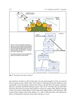
look at what shifting and rotating means. Consider Figure 9.1.
The ASL instruction moves each bit of the byte, word or long word one or more bit positions to the
left. Each time the bits are shifted, a 0 is inserted in the least significant bit position, DB0. The bit
occupying the most significant bit position, DB7, DB15 or DB31 is moved into the carry bit and
extended bit position of the condition code register, CCR. The bit that was in the CCR is discard
-
ed. Thus, if the instruction is
ASL.B #3,D0 is executed and <D0> = $AB005501. After the byte
portion of D0 is shifted three times <D0> = $AB005508. The
ASL instruction also has the effect of
multiplying the data by 2 each time the bits are shifted to the left.
Advanced Assembly Language Programming Concepts
235
The other shift and rotate instruc-
tions operate in a similar manner as
ASL and ASR. Figure 9.2 summariz-
es the behavior of these instructions.
Comparing Figures 9.1 and 9.2, we
see that some instructions seem to
exhibit identical behavior, such as
the ASL and LSL instructions, but
the
ASR and LSR instructions are
slightly different.
Let’s summarize some of the finer
points about using the shift and
rotate instructions.
• Instructions in this
group may be byte,
word or long word
operations.
• Operands can only
be the contents of
Data registers D0-D7
or the contents of
memory locations.
• When a data register
is involved, the in
-
struction must supply
the number of times
the bits are shifted.
• If the number of shifts is less than 8,use the immediate form.
• If the number of shifts is greater than 8, then the number must be in another data register.
• When a memory location is involved, only one bit is shifted at a time and the only word oper-
ands are allowed
Finally, we’ll summarize this discussion by returning to the sample program that we discussed
earlier. For the purpose of this example, we’ll assume that there are four ASCII digits located in
a memory buffer called “ascii_val”. The program will convert the ASCII characters to a 4-digit
hexadecimal number. The number will be stored back to a memory location called “hex_val”. Pay
particular attention to the way that the ASL instruction is used to move the bits.
The example program is called Get Value. It converts 4 ASCII digits stored in memory into a
4-digit long hexadecimal number.
Figure 9.1: Operation of the Arithmetic Shift Left and the
Arithmetic Shift Right Instructions.
LSB
Byte = bit 7
Word = bit 15
Long word = bit 31
X/C
ASL - Arithmetic Shift Left
0
LSB
Byte = bit 7
Wo
rd = bit 15
Long word = bit 31
X/C
ASR - Arithmetic Shift Right
Lost forever
0
X/
C
LSL - Logical Shift Left
0
X/
C
LSR - Logical Shift Right
C
ROL - Roll Left
C
ROR - Roll Right
C
ROXL - Roll
Left
X
X
ROXL - Roll
Left
C
Figure 9.2: Logical shift left/right and roll left/right instructions.
Chapter 9
236
******************************************************
* Get_value
* Converts 4 ASCII values to a 4-digit
* Input Parameters: None
* Assumptions: The buffer, ascii_val contains 4 valid ascii * characters
* in the range of 0 9, A F, or a f
******************************************************
*System equates
mask EQU $00FF * Isolates the byte value
stack EQU $B000 * Location of stack pointer
* Program starts here
ORG $0400 * Program runs here
start LEA stack,SP * Set-up the stack pointer
CLR.W D7 * We’ll need this register
LEA ascii_val,A1 * A1 points to memory buffer
MOVE.B (A1)+,D0 * Get the first byte
ANDI.W #mask,D0 * Isolate the byte
jsr strip_ascii * Get rid of the ascii code
ASL.W #8,D0 * Move left 8 bits
ASL.W #4,D0 * Move left 4 bits
OR.W D0,D7 * Load the bits into D7
MOVE.B (A1)+,D0 * Get the next byte
ANDI.W #mask,D0 * Isolate the byte
jsr strip_ascii * Get rid of the ASCII code
ASL.W #8,D0 * Move left 8 bits
OR.W D0,D7 * Add the next hex digit
MOVE.B (A1)+,D0 * Get the next byte
ANDI.W #mask,D0 * Isolate the byte
jsr strip_ascii * Get rid of the ASCII code
ASL.W #4,D0 * Move left 8 bits
OR.W D0,D7 * Add the next hex digit
MOVE.B (A1)+,D0 * Get next byte, point to con_val
ANDI.W #mask,D0 * Isolate the byte
jsr strip_ascii * Get rid of the ASCII code
OR.W D0,D7 * Add the last hex digit
MOVE.W D7,(A1)+ * Save the converted value
Advanced Assembly Language Programming Concepts
237
STOP #$2700 * Return to the simulator
***********************************************************************
* SUBROUTINE: strip_ascii
* remove the ascii code from the digits 0-9,a-f, or A-F
* Input Parameters: <D0> = ascii code
*
* Return parameters: D0.B = number 0 F, returned as 00 0F
* Registers used internally: D0
* Assumptions: D0 contains $30-$39, $41-$46 or $61-66
*
***********************************************************************
strip_ascii
CMP.B #$39,D0 * Is it in range of 0-9?
BMI sub30 * It’s a number
CMP.B #$46,D0 * Is is A F?
BMI sub37 * It’s A F
SUB.B #$57,D0 * It’s a f
BRA ret_sa * Go back
sub37 SUB.B #$37,D0 * Strip 37
BRA ret_sa * Go back
sub30 SUB.B #$30,D0 * Strip 30
ret_sa RTS * Go back
* Data
ascii_val DC.B $31,$41,$30,$30 * Test value $1A00
con_val DS.W 1 * Save it here
END $400
Arithmetic Instructions
ADD (Add binary)
Add the source and destination operands and place the result in the destination operand. A data
register must be the source or destination operand of an ADD instruction. In other words, you can
-
not directly add together the data contained in two memory locations. One of the operands must
be contained in a data register. In fact, only the
MOVE instruction is designed to operate with two
effective addresses that could be memory locations.
Let’s do an example. Assume that before the
ADD instruction <D2> = $12345678, <D3> = $5F02C332
ADD.B D2,D3
After the instruction is executed <D2> = $12345678, <D3> = $5F02C3AA
How are the condition codes affected?
• N = 1: NEGATIVE flag: Bit 7 is 1 so result is assumed to be negative.
• C = 0: CARRY flag: No carry out is generated from bit 7.
• X = 0: EXTEND flag: Used in certain operations, generally affected like CARRY.
• Z = 0: ZERO flag: Nonzero result.
******************************************************
* Get_value
* Converts 4 ASCII values to a 4-digit
* Input Parameters: None
* Assumptions: The buffer, ascii_val contains 4 valid ascii * characters
* in the range of 0 9, A F, or a f
******************************************************
*System equates
mask EQU $00FF * Isolates the byte value
stack EQU $B000 * Location of stack pointer
* Program starts here
ORG $0400 * Program runs here
start LEA stack,SP * Set-up the stack pointer
CLR.W D7 * We’ll need this register
LEA ascii_val,A1 * A1 points to memory buffer
MOVE.B (A1)+,D0 * Get the first byte
ANDI.W #mask,D0 * Isolate the byte
jsr strip_ascii * Get rid of the ascii code
ASL.W #8,D0 * Move left 8 bits
ASL.W #4,D0 * Move left 4 bits
OR.W D0,D7 * Load the bits into D7
MOVE.B (A1)+,D0 * Get the next byte
ANDI.W #mask,D0 * Isolate the byte
jsr strip_ascii * Get rid of the ASCII code
ASL.W #8,D0 * Move left 8 bits
OR.W D0,D7 * Add the next hex digit
MOVE.B (A1)+,D0 * Get the next byte
ANDI.W #mask,D0 * Isolate the byte
jsr strip_ascii * Get rid of the ASCII code
ASL.W #4,D0 * Move left 8 bits
OR.W D0,D7 * Add the next hex digit
MOVE.B (A1)+,D0 * Get next byte, point to con_val
ANDI.W #mask,D0 * Isolate the byte
jsr strip_ascii * Get rid of the ASCII code
OR.W D0,D7 * Add the last hex digit
MOVE.W D7,(A1)+ * Save the converted value
Chapter 9
238
• V = 1: OVERFLOW flag: This is tricky! The value in bit 7 of the destination register, D3,
changed, so an overflow condition may have occurred.
ADDA (Add Address)
Adds data to an address register. Only word and longword operations are allowed and the condi
-
tion codes are not affected.
ADDI (Add Immediate)
Adds number to data register or memory. Byte, word or longword operations are permitted. Con
-
sider this question. If <D2> = $25C30F7, what is the result of executing these two instructions?
Note that they differ only in the size of the operation. To check your answer, write a test program
and execute it in the simulator.
Code Example
ADDI.B #$10,D2 * <D2> = ??, C = ??
ADDI.W #$10,D2 * <D2> = ??, C = ??
CLR (Clear an operand)
The CLR instruction may be used on bytes, words and long words. All of the condition codes,
except X, are affected.
CMP (Compare data with a data register)
The CMP instruction sets the condition codes accordingly. This instruction subtracts the source
operand from the destination operand, but does not place the result back into the destination
operand. Thus, neither operand is changed. Only the condition code flags are affected.
Summary of the 68K Instructions
Rather than continue to slog through every instruction in the instruction set of the 68K, let’s briefly
summarize the instructions by functional group.
Summary of Data Transfer Instructions
EXG Exchange registers
LEA Load effective address
LINK Link and allocate
MOVE Move data
MOVEA Move address
MOVEM Move multiple registers
MOVEP Move peripheral data
MOVEQ Move quick
PEA Push effective address
SWAP Swap register halves
UNLK Unlink
Some of the data transfer instructions, such as LINK and UNLK, may seem rather strange to you.
These are special purpose instructions that only exist to support high-level languages. We’ll look at
these instructions in more detail later on in this chapter.
Advanced Assembly Language Programming Concepts
239
Summary of Arithmetic Instructions
ADD Add binary
ADDA Add address
ADDI Add immediate
ADDQ Add quick
CLR Clear operand
CMP Compare
CMPI Compare immediate
CPM Compare memory
DIVS Divide signed num.
DIVU Divide unsigned
MULS Multiply signed num.
NEG Negate
NEGX Negate with X
SUB Subtract binary
SUBA Subtract Address
SUBI Subtract immediate
SUBQ Subtract quick
SUBX Subtract with X
TAS Test and set
TST Test
EXT Extend sign
Summary of Logical and Shift
Instructions
AND Logical AND
ANDI AND immediate
OR Logical OR
ORI OR immediate
EOR Exclusive OR
EORI Exclusive OR immediate
NOT Logical complement
ASL Arithmetic shift left
ASR Arithmetic shift right
LSL Logical shift left
LSR Logical shift right
ROL Rotate left
ROR Rotate right
ROXL Rotate left with extend
ROXR Rotate right with extend
Summary of Program Control
Instructions
Bcc Branch on state of conditional
code (cc) flag
DBcc Decrement and branch on cc
Scc Set on cc
BRA Branch always
BSR Branch to subroutine
JMP Unconditional jump
JSR Jump to subroutine
RTR Return and restore
RTS Return from subroutine
Summary of Privileged Instructions
ANDI SR And immediate to Status Register
EORI SR Exclusive OR immediate to Status
Register
MOVE SR Move to/from the Status Register
MOVE USP Move to/from USP
RESET Reset the processor
RTE Return form exception
STOP Stop the processor
CHK Check register
ILLEGAL Force an illegal instruction exception
TRAP Trap call
TRAPV
Trap on overflow
ANDI CCR AND immediate to condition code
register
ORI CCR OR immediate to condition code
register
EORI CCR Exclusive OR immediate to CCR
MOVE CCR Move to/from CCR
NOP No operation - Do nothing
Summary of Bit Manipulation
Instructions
BCHG Bit change
BCLR Bit clear
BSET Set bit
BTST Test bit
Summary of Binary-Coded Decimal
(BCD) Instructions
ABCD Add BCD
NBCD Negate BCD
SBCD Subtract BCD
Chapter 9
240
The BCD instructions deserve a word of explanation. They are a legacy from the early days of
computers when many instruments were still designed using digital logic circuits that computed
results and displayed them as decimal numbers, even though they were counting in binary. A BCD
number is the same as the 4-bit hexadecimal number from 0 to 9. A BCD instruction will then gen
-
erate a carry when the count goes from 9 to A, and the digit is returned to 0. In other words, base
10 counting instead of base 16. These instructions are rarely used today.
As you can see, we have quite a variety of 68K instructions available to us to use to solve a wide
variety of real-world programming problems. The 68K instruction set architecture has stood
the test of time and is still being designed into new products. Many are designed for managing
applications running under operating systems, others to support high-level languages, and others
for handling programming exceptions. As we’ve discussed several times during this introduction
to assembly language processing, the important point is to first become comfortable with solv
-
ing an algorithm using the instructions and addressing modes that you know well, and then move
towards more efficient (and perhaps, more difficult) instructions and addressing modes. In fact,
there is nothing sub-professional about consistently using a relatively small number of instruc
-
tions. As you’ll see in the next lesson the fact that most problems are solved using a fraction of
the available instructions has led to the modern computer architecture, the reduced instruction set
computer,
or RISC.
Simulated I/O Using the TRAP #15 Instruction
This section is included because we’ll need to be able to write meaningful programs using the 68K
simulator. So far, the programs that we’ve looked at and written have been totally self-contained.
There has not been any interaction with a user. Computer programs like this are nice for studying
architecture, but they are of very limited usefulness in the real world. For a computer to be use
-
ful, we have to be able to interact with it. In this short section we’ll introduce you to a very useful
feature of the simulator, the
TRAP #15 family of I/O routines.
In the previous section you saw an instruction called
TRAP. The TRAP instruction is like a soft-
ware-generated interrupt. When the processor executes a
TRAP instruction, it will automatically
pick up the TRAP address from a fixed location in the vector table, place the return address on the
stack and begin processing at that new location.
TRAP #15 is just one of a list of TRAP locations
in the Exception Vector Table that is maintained by the processor in the memory region from $080
to $0BC.
If you enter the Teesside version of the 68K simulator and type “HE” in response to the prompt
you’ll be taken into the help facilities. The
TRAP #15 instruction is a way that the designers of the
simulator have developed to facilitate I/O between the user and the program. You can read about
the TRAP #15 instructions by studying the HELP facility that comes with the E68K program.
Alternatively, you can read up on the
TRAP #15 facility in Clements
1
.
Remember, the
TRAP #15 instruction is an artifact of the simulator. It was designed to allow I/O
to take place between the simulator and the user. If you were really writing I/O routines, you prob
-
ably would do some things differently, but lots of the things are the same.
Advanced Assembly Language Programming Concepts
241
Associated with the TRAP #15 instruction are various tasks. Each task is numbered. Associated
with each task is an application programmer’s interface, or API, that explains how it does its
work. For example,
task #0 prints a string to the display and adds a newline character so that the
cursor advances to the beginning of the next line. In order to use
task #0 you must set up the fol-
lowing registers (this is the API):
• D0 holds the task number as a byte,
• A1 holds the memory address of the beginning of the string,
• D1 holds the length of the of the string to print,
Once you’ve set-up the three registers, you call
TRAP #15 as an instruction in your program and
you’re message will be printed to the display. Thus, the
TRAP instructions are used as an interface
between the 68K simulator and your PCs operating system. Here’s a sample program that illus
-
trates how it works. To output the string, “Hello world!” you could use the following code snippet.
“Hello World!” Example
*************************************************
*
* Test program to print a string to the display
*
*************************************************
OPT CRE
task0 EQU 00
ORG $400
start MOVE.B #task0,D0 * Load task number into D0
LEA string,A1 * Get address of string
MOVE.W str_len,D1 * Length of the string in D1
TRAP #15 * Do it
STOP #$2700 * Back to simulator
* Data area
string DC.B ‘Hello world’ * Store the message here
str_len DC.W str_len-string * Get the length of the string
END $400
Look at the line:
str_len DC.W str_len-string * Get the length of the string
What’s going on? We’re letting the assembler do some work for us. The assembler is calculat-
ing the length of the string by subtracting the address of the start of the string (labeled “string”)
from the first address after the string, (labeled “str_len”). It is also a fairly common technique in
assembly language to use this method to calculate the distance (in memory locations) between two
places in the program. When you subtract pointers in C++ you’re doing the same thing.
Chapter 9
242
Task #1 is almost identical to task #0 except that it does not print the “newline” character. This is
handy when you want to prompt the user to enter information. So, you would issue a prompt using
task #1 rather than task #0 .
Also, you might want to get information from the user. Such as where do they want to run the
memory test and what test pattern do they want to use. You might also ask them if they want to run
the test again with a different pattern.
Task #2 is another very useful function. Upon executing this instruction the simulator will wait for
you to enter a string from the terminal, terminated by the ENTER key. The simulator will place the
character string that you entered into a memory buffer pointed to by A1.
The TRAP #15 has a number of facilities. The best way to understand how to use them is to read
about them first, and then write several small test programs to test your knowledge.
Compilers and Assemblers
Up to now we’ve been keeping our distance from higher level languages, like C and C++. We did
take a brief excursion to look at how we could mimic some typical C loop structures using assem
-
bly language, but for the most part, we’ve kept the two languages apart.
However, it should not come as a surprise that even though we might be writing a program in
C++, we may be debugging in assembly language. Also, from the point of view of a computer’s
architecture, to try to understand why certain instructions and addressing modes exist at all. While
a complete study of how a compiler does what it does and utilizes a computer’s instruction set
architecture is beyond the scope of this book, it can’t hurt to take a peek under the covers and look
at how the compiler does what it does. Therefore, we’re going to see how a C language cross-
compiler converts a C source file into assembly language.
Consider the following simple C program:
int funct(int,int *) ;
void main()
{
int i = 0, aVar = 5555, j ;
i++ ;
j = funct(i, &aVar );
j++ ;
}
int funct( int var, int * aPtr )
{
return var + *aPtr ;
}
Here we declare 3 variables, i, j and aVar and do some simple manipulation. Of note, we pass two
variables into the function,
funct. One variable, i, is passed by value and the other variable, aVar, is
passed by reference. This program was then compiled using a 68000 cross compiler manufactured
Advanced Assembly Language Programming Concepts
243
by the Hewlett-Packard Company® (HP) several years ago for use with its embedded software de-
velopment tools. This compiler generates an assembly language source file that is then assembled
using a 68000 assembler, also manufactured by HP.
Here is the 68000 assembly language code created by the compiler for this program. The actual
assembly language instruction or pseudo instructions are shown in gray colored font. I’ve added
the gray colored blocks in order to explain why and what the compiler is doing. This assembly
language source file would then be assembled by a 68000 assembler and an object file would be
created. Modern C or C++ compilers generally skip the assembly language source file generation
process and go right to the object code. However, for our purposes, this “old-fashioned” compiler
allows to see exactly what is going on.
CHIP 68000 NAME test3
CHIP: 68000 tells the assembler to use only 68000 conventions
NAME: tells assembler the name of the relocatable module to create
* Assembler options:
OPT BRW,FRL,NOI,NOW
OPT BRW: All branches should use 16-bit displacements
OPT FRL: All forward references to absolute addresses should use
32-bit mode
OPT NOI: Do not list instructions that are not assembled due to
conditional variables
OPT NOW: Do not print warnings during assembly
*
* Macro definition for calling run-time libraries:
* bytes per call = 6
*
CALL: A macro that takes as a dummy input parameter “routine” and
generates the defined sequence of instructions each time it is used
in place of an instruction. Macro definitions are a convenient way to
group several assembly language instructions under the umbrella of a
new instruction. In this case, it will be used to access a run-time
subroutine that is located in a library module that will be pulled in
when the program is linked together.
XREF is a pseudo op code that tells the assembler that routine is
defined in another file.
CALL MACRO routine
XREF routine
JSR (routine,PC)
ENDM
SECT: A pseudo-op that indicates that is a relocatable code block
named “prog”. The C indicates it is a code segment (instructions) and
that it is section #2. The “P” is an internal HP type designator.
Chapter 9
244
The compiler often inserts NOP instructions in front of function calls
to aid in debugging.
SECT prog,2,C,P
NOP
NOP
NOP
Watch for interspersed C code and assembly code. The compiler will
insert the C source instructions as comments in the assembly code. I
added the next two instructions so that it would run in our simulation
environment.
ORG $400
LEA $1000,SP
* 1 int funct(int,int *) ;
* 2 void main()
* 3 {
XDEF: A pseudo op that tells the assembler that this function name,
“_main”, should be made available to other modules at link time. Thus,
the completed program knows where to begin.
XDEF _main
LINK: This instruction establishes the stack frame. Register A6 is the
stack pointer for this function’s (_main) stack. The instruction does
several things:
1. The current value of A6 is pushed onto the stack,
2. The current value of the stack pointer, SP (A7), is transferred to
A6,
3. The sign-extended, 16-bit displacement, -4, is added to the stack
pointer in order to reserve 4 bytes on the stack. Thus, A6 is now a
local stack pointer with a 4-byte stack. The system stack pointer, SP,
sits below it. This operation reserves the space that the function
main() needs to store its local variables.
_main
LINK A6,#-4
MOVE.L D3,-(A7) * Save the current value of D3
MOVE.L D2,-(A7) * Save the current value of D2
MOVEQ #$FF,D1 * Not exactly sure why
MOVE.L D1,(-4,A6)
* This puts FF at the bottom of the stack frame for _main
MOVEQ #$FF,D2 * Who knows?
MOVE.L D2,D3 * Ditto
Advanced Assembly Language Programming Concepts
245
Register ‘D2’ is register variable ‘S_i’. The compiler is smart
enough to realize that it can save variables in registers instead of
memory, thus running the program more efficiently. Below, it initial-
izes D2 to 0.
MOVEQ #0,D2
SET is a pseudo op code that gives a number a value that can be reas-
signed. A variable given a name with the equate psuedo-op (EQU) can’t
be reassigned a new name or value.
S_aVar SET -4
The value 5555 is placed in the stack frame. Register ‘D3’ will be
assigned to the register variable ‘S_j’. The ADDQ instruction imple-
ments i++
MOVE.L #5555,(S_aVar+0,A6)
* 4 int i = 0, aVar = 5555, j ;
* 5 i++ ;
ADDQ.L #1,D2
* 6 j = funct(i, &aVar );
The address of aVar will be placed in A0 and then the contents of
the address that A0 is pointing to will be pushed onto the stack.
This next block of code is called a prologue. Code like it is gener-
ated whenever there is a function call made, or as we know it, a JSR
instruction. Here:
• A0 holds the address of aVar
• The address of aVar is pushed onto the stack.
• i is pushed onto the stack
• The JSR instruction is implemented using PC relative addressing
LEA (S_aVar+0,A6),A0
PEA (A0)
MOVEA.L D2,A0
PEA (A0)
JSR (_funct+0,PC)
ADDQ.L #8,SP * main goes out of scope
MOVE.L D0,D3 * D0 is the return register from JSR
* 7 j++ ;
ADDQ.L #1,D3 * This is j++
* 8 }
Chapter 9
246
The closing brace “}” causes the following function exit code to be
generated.
functionExit1 NOP
MOVE.L (A7)+,D2 * Restore D2
MOVE.L (A7)+,D3 * Restore D3
UNLK A6 * De-allocate stack frame
returnLabel1 RTS
NOP
NOP
NOP
* 9 int funct( int var, int * aPtr )
* 10 {
XDEF _funct
Here is the subroutine entry point for “_funct”. Notice how the
compiler creates an assembly language label for the subroutine by
placing an underscore character “_” in front of the function’s name.
Also notice that the function does not appear to need any variable
storage space when the stack frame is allocated.
_funct
LINK A6,#-0
S_var SET 8
S_aPtr SET 12
* 11 return var + *aPtr ;
This next block of code is quite interesting. Before the pointer is
de-referenced to return the value of aVar, the compiler checks to see
if the address of aVar is a NULL pointer. If it is, it calls a runtime
error handler. This was the purpose of generating the MACRO code. The
instructions do the following:
• Get the value of aVar from the stack and put it in A0.
• Move A0 into D1 to force the Z flag to be set if <A0> = 0
• If A0 = 0 then there is a NULL pointer
• If the pointer is bad it does a JSR to the library routine
“ptrFault”
MOVE.L (S_aPtr+0,A6),A0
MOVE.L A0,D1
BEQ.S L0_APtrChk
MOVEQ #$FF,D0
CMP.L D0,D1
BNE.S L0_BPtrChk
L0_APtrChk
CALL ptrfault