Brief summary of engineering doctoral thesis: Analysis of influencing parameters and basics of determining resistance factors of drilled shafts used in bridge substructures in Ho Chi Minh city
Bạn đang xem bản rút gọn của tài liệu. Xem và tải ngay bản đầy đủ của tài liệu tại đây (752.44 KB, 27 trang )
1
MINISTER OF EDUCATION AND TRAINING
UNIVERSITY OF TRANSPORT AND COMMUNICATIONS
NGO CHAU PHUONG
ANALYSIS OF INFLUENCING PARAMETERS AND BASICS
OF DETERMINING RESISTANCE FACTORS OF DRILLED
SHAFTS USED IN BRIDGE SUBSTRUCTURES IN HO-CHI-
MINH CITY
MAJOR: BRIDGE AND TUNNEL ENGINEERING
CODE: 62.58.02.05.03
BRIEF SUMMARY OF ENGINEERING DOCTORAL
THESIS
Hanoi-2014
2
This thesis completed at: Faculty of Civil Engineering
University of Transport and Communications
SUPERVISORS:
1. Assoc.Prof. Dr. Tran Duc Nhiem
2. Assoc.Prof.Dr. Nguyen Ngoc Long
Reviewer 1: Prof. Dr. Nguyen Nhu Khai,
National University of Civil Engineering Vietnam.
Reviewer 2:
Prof. Dr. Nguyen Dong Anh,
Institute of Mechanics Vietnam.
Reviewer 3: Dr. Do Huu Thang,
Institute of Transport Science and Technology Vietnam.
Thesis is defended in front of the University-
Graded Committee of
thesis evaluation according to Decision #1359/QĐ-ĐHGTVT, on date
17
th
June 2014
signed by the Rector of University of Transport and
Communications on date………………… 2014.
Readers can find this thesis at:
- Vietnam National Library
- Library of the University of Transport and Communications
1
INTRODUCTION
By applying statistics and probability and reliability theory to
engineering foundations, the thesis proposes a pattern to determine
resistance factors of drilled shafts used in bridge substructures based on
statistics characteristics of the ratio between real measured values and
estimated values for Resistance (R) and load effect (Q). Then, by analyzing
statistics characteristics of the capacity based on 24 results of static axial
compressive load test of drilled shafts that were constructed by the wet
method (bentonite) in cohesive and non-cohesive composite soils in Ho-
Chi-Minh city, the thesis captures the determination of resistance factors
for four different calculation methods of pile resistance design based on soil
base strength condition.
Literature Review:
Drilled shafts construction technology was first used in America (1890),
in over the word (1950) and in Vietnam (1990). However, the calculation
theory has been developed more slowly. One of the trends in the world is to
research new problems of applying statistics and probability theories and
reliability theory to correct resistance factors based on statistics
characteristics of the ratio between real measured values and estimated
values for Resistance (R) and load effect (Q) extracted from a reasonable
number of construction projects. Research results are gradually applied to
update and to implement for some clauses in standards or specifications and
design instructions of developed countries such as in Europe, Japan…and
America.
Over two more recent decades in Vietnam, accompanied with the
development of infrastructure in great scale built in soft soil bases or in
urban areas, drilled shafts foundations becomes one of the best solutions.
The foundations are also widely applied in Ho-Chi-Minh city. However,
there is not any backgrounds to determine resistance factors of drilled
shafts based on analyzing statistics characteristics and reliability analysis
using current advanced theories.
Therefore, studying of the backgrounds to determine the resistance
factors based on reliability analysis is new and attracts international and
domestic researchers. It is the reason why I selected this topic to research.
2
Thesis title: “Analysis of influencing parameters and bases to determine
resistance factors of drilled shafts used in bridge substructures in Ho-Chi-
Minh City”.
Objectives: Determine resistance factors according to soil base strength
which is equivalent to methods presented in specifications being applied.
Structure: Drilled shafts used in bridge substructures.
Research Scope: Predictive resistance and real resistance obtained from
the results of static axial compressive load tests for drilled shafts in Ho-
Chi-Minh City casted in cohesive and non-conhesive composite soils (sand,
sandy, clay, clay mud, ) by wet method; to determine general resistance
factors according to soil base strength condition for four different methods
of pile resistance design: 1) Russian Method specified in TCXDVN 205-
98; 2) Japanese Method (JRA 2002 SHB -Part IV); 3) Reese&O'Neill
(1988) and 4) O'Neill&Reese (1999). Problems relating to load statistics
characteristics, general resistance factors for various types of soil, local
areas, and type of structure as well as pile shalf and tip resistance factors
are not performed in this thesis and they are recommented for future
studies.
Scientific and practical meaning of the topic:
- Apply advanced theories of statistics analysis and reliability to
propose a pattern to determine resistance factors of drilled shafts based on
statistics data of the ratio between real measured values and estimated
values for Resistance (R) and load effect (Q).
- The thesis has analyzed and determined statistics characteristics of
the ratio between real measured values and estimated values; to determine
resistance coefficients for the four methods from 24 static load test results
of drilled shafts constructed in cohesive and discrete composite soils in Ho-
Chi-Minh city subjected to static axial compression and other applicable
data.
- Research results of the thesis can be used as reference documents in
design bearing capacity of drilled shafts used for bridge substructures
constructed in Ho-Chi-Minh city or similarly geological areas.
Chapter 1. GENERAL
1.1. Drilled shafts and its application in infrastructure construction
3
1.1.1. Definitions, structural characteristics and technology
Drilled shafts of bridge substructures (Drilled Shafts) : are a part of piers
and abutments; they are constructed by raw concrete casting in pre-bored
holes with or without steel case inside. The piles are subjected to loads
transferred from foundation foots and then transfers the loads into
surrounding soil base.
Wet drilled shafts construction method (wet method): to drill holes and
to cast the piles in water or in bore mud and a temporary tube wall segment
is put in the boring hole top. Applicable for cohesive, discrete and high
groundwater level areas.
Drilled shafts cross-section maybe cylindrically constant throughout the
pile length, this pile type is called simple one; or cylindrical-shaped but
widened at bore hole tip area.
1.1.2. The utilization of the pile in Vietnam and in the world
Through analysis, the author recognizes the need to use the drilled shafts is
growing both in Vietnam and in the world. Almost foundation solutions for
traffic, civil and industries from medium to large scale in Vietnam are using
drilled shafts foundations.
1.1.3. Current status and characteristics of drilled shafts used in HCM City
Through analysis, the drilled shafts foundation for constructions here is also
applied a lot in recent years. Most of the piles are constructed by the wet
method (in bentonite) through the mixture soil layers with combined cohesive
and discrete soils, these layers can be weak, average or good in load bearing.
1.1.4. Some structural characteristics, drilled shafts technology in Vietnam
Due to the characteristics of the technology, the complexity of geology;
experience level of the participants in the management, design and
construction limits and especially the system of processes, standards are still in
the process of integration and are not complete and existing many problems.
Therefore, the quality of the drilled shafts or pile resistance depends very much
on the aforementioned elements.
1.2. Design drilled shafts based on reliability according to Load and
Resistance Factor Design method (LRFD)
The design method LRFD is based on reliability,as the load effects with their
particular factors (Q
tk
) shall not exceed the resistance with their particular factors
(R
tk
)
Through analysis of the historical development of the design philosophies
and design standards such as Allowable Stress Design (ASD), Limited States
Design or Load Factor Design (LSD; LFD), Reliability- Based Design (RBD)
and the method with reliability factors separately or Load and Resistance
4
Factor Design (LRFD), the author found that design calculations of drilled
shafts foundation according LRFD method is an advanced method and have
being trusted and applied by many countries in the world.
1.3. Analysis of literature to determine drilled shafts resistance factors
based on reliability used for bridge substructures in the world
1.4. Analysis of literature showing the LRFD application and
determining resistance factors for bridge design in Vietnam
1.5. Current challenging problems
Some current problems in bridge design standards 22TCN272-05 and
AASHTO LRFD 2012 (2007) are shown in Table 1.1.
Table 1.1. List of current problems in the standards 22TCN272-05 and
AASHTO LRFD 2012 (2007)
Problem
22TCN272-05
AASHTO LRFD 2012 (2007)
Method for determination
of resistance in cohesive
and
discrete soil
05 methods existed
from before 1988
01 method
O'Neill&Reese (1999)
Resistance factors are not
specified for:
Sandy soil, cohesive
and discrete soil
Cohesive and discrete soil
Officially Applied Year
2005
2007
Determination of ultimate
resistance under static load
Many method based
on TCXDVN269-
2002
5% pile diameter or merged
settlement pile
Recomendations when
resistance factors used
The resistance factors are not the standard values for
all states of America and of course not accurate for
other countries, including Vietnam
Some shortcomings of the related scientific studies:
- The study of resistance factors correction of deep foundation of
Paikowsky et al (2004): Didn’t mention the resistance factors of method
O'Neill & Reese (1999), just mention method Reese & O'Neill (1988) for
sandy and clay mixture soil conditions on the basis of 44 load test results of
drilled shafts in Florida.
- Liang (2009): Proposed resistance factors for method O'Neill &
Reese (1999), but only suggested for sandy and clay conditions in the U.S.
- Murad et al. (2013): Proposed resistance factors for method O'Neill
& Reese (1999) for mixed cohesive and discrete soil condition in Louisiana
& Mississippi on the basis of 34 pile load test results, but there were 26
values extrapolated to static load test results due to not try to break the pile.
- There is no study regarding the research objectives of this thesis in
Vietnam.
5
From the above-mentioned problems, the author proposes the targets,
content and research methodology of the thesis as decribed in items 1.6 and
1.7.
1.6. Targets of the topic
Quantitative study of factors affecting the estimated resistance results of
the four methods compared with actual field resistance of drilled shafts
under the ground conditions in the area of HCMC. This means that the
author has determined the statistics characteristics of the ratio of the real
measured resistance and the expected one (resistance bias factor, λ
R
);
To research the basis of determining the resistance factors and to
propose the resistance factors for drilled shafts foundations of bridge
substructures in HCMC area for the four methods.
1.7. Content and Research Methodology
To research the basis of determining the resistance factors for drilled
shafts using probability and statistics theory and advanced reliability
theory. Specifically, the survey collected from 24 results of static pile load
tests in HCM City, the author conducted a study to identify typical statistics
of the ratio of the measured and estimated resistances (Resistance bias
factor, λ
R
); From that way, the authod determined the resistance factors for
the four methods on the basis of reliability analysis.
Chapter 2. DETERMINATION OF RESISTANCE FACTORS OF
DRILLED SHAFTS BASED ON RELIABILITY THEORY
According to AASHTO LRFD, drilled shalfs axial resistance factors
according to soil base strength condition are factors determined based on
the statistical characteristics of the nominal resistance, mainly calculated
from the variability of characteristic parameters of the ground around the
pile, the pile size, level of expertise (professional) of human - device
participating in the implementation phase of the project and the uncertainty
of prediction method for nominal resistance; but also related to the
statistical characteristics of load effects through the identification process.
2.1 Method to analyze the statistical characteristics
2.1.1 Determination of minimum size of samples
Sample size is estimated by: (2.1)
In which: σ
and z
α/2
, z
θ
: common standard deviation and standard deviation
with error probabilities α, θ from the normal distribution; ɛ: allowable
error; C: is a constant related to error probability Type I and Type II.
2
/2
22
()
/
zz C
n
( ) (ES)
αθ
εσ
+
= =
6
For example, to determine the sample size for the thesis: With some
prediction methods of drilled shafts resistance that accept averaged
estimated error of about 50% (=1/FS, FS=2: safety factor) with reliable
interval of 0,95 (i.e., α=0,05) and θ = 0,2. Previous studies indicate
standard deviations of the resistance bias factor from 0,27 to 0,74. Thus, the
effect factor is: ES = 0,5/0,74 = 0,456 and C=7,85. By applying the formula
(2.1) to estimate the required sample size for the study:
To compare with recommendation of Murad (2013), the number of test
piles for the study area at least is ≥ 20 piles. Thus, with 24 results of static
axial compressive load tests for drilled shafts in Ho Chi Minh City area can
be considered reliable enough for analysis in order to meet the research
objectives of the thesis.
2.1.2 Testing method of suitable probability distribution for the random
bias factor
Through analysis, the Shapiro-Wilk method or the Pearson chi-square
(when the sample size is less than 50) is recommended with the following
principles: the empirical distribution consists with assumed theoretical
distribution (standard or logarithmic, ) when the match probability (P) is
greater than 0.05.
2.1.3 Correction method for statistical characteristics of random bias factor
For foundation structures, the laws of probability distributions of
random bias factor often match or nearly match the normal standard
distribution or standard logarithm.
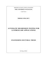
Through research, the authod
proposes two correction methods of
statistical characteristics for
logarithmic distribution form
according to the
the principle (Allen,
2005): Based on the graph of the
cumulative probability function to
examine the conformity with one of
the two cases, 1) consistent with the
entire collection data (FTAD method
-fit to All data) or 2) only consistent
with the area of
small values at
distribution tail (BFTT-Best method
fit to tail) (Figure 2.1)
Figure 2.1. Cumulative probability
density function of resistance bias
factor
1
2
3
2
7,85
17,2 17( )
0,5 / 0,74
n samples
()
= = >
7
2.2 Reliability Analysis Method
When analyzing the reliability, the incident probability is the condition
that the limited state has been reached. The adjustment factors are selected
to ensure that incident probability of each limited state is very small and
acceptable. The probability density functions of load effects (Q) and
resistance (R) with the assumption of two independent normally distributed
variables (Figure 2.2). Safety range or the safety factor is the difference
between R and Q, the quantitative quantity for the safety is reliability or
safety probability, P
s
:
P( ) P( - 0) ( )
s
P R Q G RQ
β
= > = = >=Φ
(2.2)
Incident probability: P
f
is calculated as:
( )
P 0 1- 1 ( )
fs
PG P
β
= < = = −Φ
(2.3)
In which: Φ(.): normalized distribution functions; β: index of reliability.
Index of reliability is determined based on averaged number and
standard deviation as follows:
22
-
RQ
G
G
RQ
µµ
µ
β
σ
σσ
= =
+
(2.4)
Figure 2.2.
Normalized distribution probability density
functions
Figure 2.3. Normal Logarithm
distribution probability density
function
If R and Q follows the normal logarithm distribution, safety range, G, is
determined as follows: (Figure 2.3):
G=ln(R)-ln(Q)=ln(R/Q) (2.5)
Here, β is determined as the ratio of logarithm averaged number
G
and
logarithm standard deviation, ξ
G
.
G
G
β
ξ
=
(2.6)
2.3 Methods to determine pile body resistances
The thesis has researched four methods to determine the pile body
resistance: Method in accordance with the safety factor of the design
philosophy of allowable stress (ASD); first-order secondary moment
8
method (FOSM); First-order reliability method (FOSM); Monte Carlo
method (MCS). After analyzing the advantages and disadvantages of these
four method, the author proposes to select Monte Carlo analysis method to
determine the resistance factorss.
Safety range, G, is applied to determine resistance factors as R and Q
follow the normal logarithm distribution:
()
f( , ) ln
()
D
RD L
L
D
DL
L
Q
Q
RQ G
Q
Q
λγ γ
ϕλ λ
+
= =
+
(2.7)
2.4 Propose a procedure and pattern to determine the resistance
factors
The procedure and pattern to determine the pile resistance factors
comply with the ensurement basis of target reliability as follows:
1. To determine limited state according to soil base strength conditions
for drilled shafts (22TCN272-05, AASHTO LRFD), strength state function:
g(R,Q)=
ϕ
R – (γ
D
Q
D
+γ
L
Q
L
)= λ
R
(γ
D
k+γ
L
)/
ϕ
- (λ
D
k+ λ
L
);
2. To select statistical parameters of design load effect (Q) and load
factors: the representive is static load bias factor (λ
D
) and live load effect
bias factor (λ
L
) complied with the standard AASHTO LRFD.
3. To analyze the statistical characteristics of resistance (R): the
representive is resistance bias factor, λ
R
, which is the ratio of measured
ultimate resistance (R
td
) and predicted nominal resistance (R
dt
):
a. To determine the measured ultimate resistance R
td
from results of pile
static load tests according to soil base condition, this is the trial load value
at a settlement of 5% of pile diameter or merged settlement pile (AASHTO
LRFD 2012, TCVN 9393-2012);
b. To predict the nominal resistance (R
dt
) based on calculation theory;
c. To determine the resistance bias factor, λ
R
=R
td
/R
dt
;
d. To analize, calculate the statistical parameters (μ, σ) and to verify the
form of distribution density function (standard, logarithm, ) suitable for λ
R
;
4. To analyze and to determine the resistance factors of drilled shafts
(
ϕ
) on the basis of analyzing reliability follwing Monte Carlo method with
the target reliability index satisfied, β
t
;
5. To recommend to correct the resistance factors for calculation
method.
The above procedure is shown in Figure 2.4.
9
Figure 2.4. Analysis model to determine pile resistance factors on the
basis of ensuring the target reliability index
Results obtained in Chapter 2
- Recommend to use relative random resistance bias factor (λ
R
) with a
minimum sample size of 20 to analyze statistical characteristics. When
choosing a probability distribution function (cumulative), it is needed to
consider between 2 cumulative distribution functions which fit to the entire
real values (FTAD) and cumulative distribution function calibrated in
accordance with the actual value area at the tail of distribution (BFTT).
- Recommend to use Monte Carlo method to analysis the reliability as
a basis for determining pile resistance factors and to use the first-order
reliability method (FORM) for validation.
- Propose a procedure and a pattern to determine pile resistance factors
as shown in item 2.4.
Chapter 3. ANALYZING THE PARAMETERS INFLUENCING TO
RESISTANCE FACTORS OF DRILLED SHAFTS USED IN
BRIDGE SUBSTRUCTURES IN HO CHI MINH CITY
Define the failure condtion of drilled shafts
piles based on soil base
(AASHTO LRFD, 5% pile
diameter of merged)
Determine limit state based on soil base for
drilled shafts piles (strength, service states)
Strength state function: g(R,Q)=
ϕ
R – (γ
D
Q
D
+γ
L
Q
L
)
Determine statistical characteristics for 2 random variables
(R: resistance, Q: load effect):
R
epresentive of R is resistance bias factor, λ
R
=R
td
/R
dt
Representive of Q is load effect bias factor, (λ
D
, λ
L
)
Determine λ
R
, is the ratio of measure ultimate
resistance, R
td
and predicted nominal resistance, R
dt
Apply the statistical characteristics to
deadload and live load effect bias factor (λ
D
,
λ
L
)
according to
AASHTO LRFD
Analysis and calculate the statistical
characteristics
(μ, σ, V) and verify distribution
density function (standard, loga…) suitable for λ
R
Determine reliability index,
β
and
incident probability, P
f
Select target reliability index
β
t
(refered to AASHTO LRFD
:
β
t
=3,0)
Determine resistance factors
ϕ
based on Monte
Carlo (MCS) method or fisrt-order reliability method
(FORM)
Compare and evaluate the study results with
other literature
11 Propose to correct resistance factors for
estimated axial resistance method following
soil base strength condition
Evaluate the
reliability index
10
The parameters that influence the results of determining of pile
resistance factors described in Figure 3.1.
Figure 3.1. Parameters influencing to determinging of resistance factors (φ)
3.1 Uncertainty factors and statistical characteristics of load effect
In Vietnam, there is no research conditions to determine the rules of
distribution of load effects, the author proposes to apply the statistical
characteristics and other factors regulated by the AASHTO LRFD design
as:
γ
L
=1,75,
λ
L
=1,15, V
L
= 0,18;
γ
D
= 1,25,
λ
D
=1,08, V
D
= 0,13, Q
D
/Q
L
=3.
where:
λ
D
and
λ
L
are deadload and live load effect bias factor. V
D
and V
L
are
variation coefficients of dead load and live load; the ratio Q
D
/Q
L
is of dead
load and live load.
3.2 Uncertainties affecting to drilled shafts resistance
The uncertainties affecting the predicted pile resistance should be
analyzed to determine the resistance factors for methods to ensure required
reliability and they are divided into four main groups: 1). The diversity, the
unusual geological structure; 2). The error of measurement (measuring,
surveying, testing of characteristic parameters of the material, structure or
soil base); 3). The model error and 4). Quality of project administration and
construction experience (According to Phoon and Kulhawy (1999),
Paikowsky (2004)).
To describe the general characteristics of these uncertainties, relative
random resistance bias factor (λ
R
) as outlined in Chapter 2 can be used.
3.3 Analyzing selection of methods to predict drilled shafts
resistance
On the basis of several popular methods of pile resistance prediction in
Vietnam and overseas, the author selected four methods according to soil
base condition as mentioned in the research scope.
Real geological
layer profile
Model of (MH) soil
base
Model MH applied
for design CKN
Result in (φ)
Target reliability index (βt)
Abnormal profile +
measurement error
(khả át )
Error due to MH:
MH predict uncertain R
Statistical error
discrebing factos:
MH predicts uncertain Q
γ (ϲ, φ
o
, N,…)
γ (ϲ, φ
o
, N,…)
Su (qu,…)
μ ± σ
μ ± σ
Quality of construction organization, management and operation based on reliability analysis
11
The formula to determine the unit resistance at the pile tip and pile shaft
according to the two standards are briefly introduced in Table 3.1 and Table
3.2.
3.4 Selection of method to determine actual measured ultimate
resistance of drilled shafts
Table 3.1. Summary of formula to determine nominal unit resistance of drilled
shafts according to 22TCN 272-05 and AASHTO LRFD 2012
22TCN 272-05 (brief RO88-272)
AASHTO LRFD 2012 ( brief OR99-AL12)
Unit shaft
resistance, q
s
Unit tip resistance, q
p
Unit shaft resistance, q
s
Unit tip resistance, q
p
1. Cohesive soil (clay, soil with clay dust content higher 50%)
q
s
= α S
u
(MPa)
S
u
(MPa)
α
<0,2
0,55
0,8-0,9
0,31
>0,9
-
q
p
=N
c
S
u
≤4 (MPa),
where:
6[1 0, 2( / )] 9
c
N ZD=+≤
,
với S
u
≥0,024MPa;
0,67 *6[1 0,2( / )] 9
c
N ZD=+≤
with S
u
<0,024MPa
q
s
= α S
u
(MPa), where:
α =0,55, với
/ 1, 5
ua
Sp≤
0,55-0,1( / -1,5)
ua
Sp
α
=
with
1,5 / 2,5
ua
Sp≤≤
q
p
=N
c
S
u
≤4 (MPa),
where:
6[1 0, 2( / )] 9
c
N ZD=+≤
với S
u
≥0,024MPa;
0,67*6[1 0,2( / )] 9
c
N ZD
=+≤
with S
u
<0,024MPa
2. Discrete soil (sandy soil, soil with sand dust content higher 50%)
'
0,19
v
s
q
βσ
= ≤
,
with 0,25≤
β
≤1,2
where:
3
1, 5 7, 7 10 z
β
−
=−×
q
p
=0,057N,with N≤75
;
=4,3
p
q
, with N>75
'
0,19
v
s
q
βσ
= ≤
, with , 25≤
β
≤1,2
where
:
3
1, 5 7, 7 10 z
β
−
=−×
, with
N
60
≥15;
3
60
(1, 5 7, 7 10 )
15
N
z
β
−
= −×
,
with N
60
<15
q
p
=0,057N
60
, with
0,57N
60
≤50;
0.8
''
60
0,59 *
p av v
q Np
σσ
=
,
with N
60
>50
Table 3.2.Summary of formula to determine nominal unit resistance of drilled
shafts according to TCXDVN 205-98 and JRA 2002-Part IV
Russian method in TCXDVN 205-98
(brief SNIP-205)
JRA 2002-Part IV
(brief SHBP4-JRA02)
Unit shaft
resistance, q
s
Unit tip
resistance, q
p
Unit shaft
resistance, q
s
Unit tip
resistance, q
p
1. Cohesive soil (clay, soil with clay dust content higher 50%)
2≤ q
s
≤100(kPa),
Refered to table A.2, with 0,2 ≤ I
L
≤ 1
and 1m≤ h
tb
≤35m
250≤q
p
≤4500 (kPa),
table A.7, with, 0 ≤ I
L
≤ 0,6
and 3m ≤h
mc
≤40m
q
s
=q
u
/2 or
q
s
=c or
=10N≤150(kPa)
q
p
= 3q
u
or
=60N ≤ 9000(kPa)
2. Discrete soil (sandy soil, gravel, soil with sand dust content higher 50%)
15≤q
s
≤100(KPa),
Refered to table A2,
for medium tight
sand has grain components: coarse,
fine, dust. If tight state used, then q
s
increased by 30%; and 1m≤h
tb
≤35m
q
p
=0,75.
β
(
γ
1
'.d
p
.A
k
o
+
α
.
γ
1
.h
mc
.B
k
o
), with:
β
; A
k
o
;
α
; B
k
o
refered to table A.6,
with 24
o
≤
ϕ
ο
≤ 39
o
,
4 ≤h/d≤25 and
0,8≤d≤4m
q
s
=2N≤200(kPa)
Sandy soil, gravel:
q
p
=70N≤3000(kPa),
with N≥30;
Hard gravel:
q
p
=5000(kPa), with
N≥50
12
To ensure the consistency with
the design philosophy of drilled
shafts in
LRFD method, the author
proposes to select actual measured
resistance value in accordance with
the AASHTO LRFD standards as
outlined
(referred to as AASHTO
method) when analyzing to
determine resistance factors.
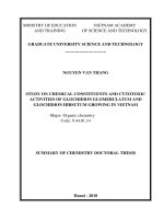
In AASHTO LRFD 2007, actual
measured pile body resistance
is the
load at which settlement of pile top
equals 5% of pile diameter or pile is
merged (Figure 3.2).
Figure 3.2. Trial loading and settlement
relationship
3.5 Analyzing the statistical characteristics for resistance bias factor of
drilled shafts based on soil base strength in Ho Chi Minh City
3.5.1 Survey to collect data base of static axial compressive load tests to serve
for current research.
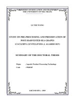
The survey collected 24 profiles of static axial compressive load tests
for drilled shafts (including geological survey reports, topographical,
design dossiers and dossiers of pile construction quality management)
which meet the requirements of statistical studies in Figure 3.3, Table 3.3
and Table 3.4 (see details in Appendix 1).
Characteristics of this data set is the same method of construction in
bentonite mortar (wet technology); geological conditions are similar
mixture soil (cohesive and discrete): mud clay, silt, clay, loam, sand, clay
sand (mainly forming pile skin resistance ); but different in size (diameter
from 1m-2m, length from 25m-85m) and location (Table 3.3).
13
Geological characteristics at the
testing place can be considered as
the
representative for the type of
the cohesive and discrete mixture
soil in HCM City in particular, the
layer profile is formed
from river
sediments, sea (clay mud, muddy
sand, sandy loam, sandy clay and
sand). Stratigraphic distribution:
the top layer is soft soil (clay mud,
sand mud) with
up to 35m in
thickness, the SPT index (N <5);
the beneath layers are clay layer,
sandy clay, sand and clay sand at
the depth up to 100m, the SPT
index (N = 10 to
> 50 (Table 3.3,
Appendix 2, 4).
PT4
TỈNH ĐỒNG NAI
Huyện Cần Giờ
TỈNH LONG AN
TỈNH BÌNH DƯƠNG
Huyện Củ Chi
PT6
PT1
1
PT22
PT24-PT25
PT10
PT26-PT27
PT16-PT18
PT7-PT9
PT3
PT2
PT1
PT5
PT12
PT19-PT21
PT23
TP HỒ CHÍ MINH
PT4
TỈNH ĐỒNG NAI
Huyện Cần Giờ
TỈNH LONG AN
TỈNH BÌNH DƯƠNG
Huyện Củ Chi
PT6
PT1
1
PT22
PT24-PT25
PT10
PT26-PT27
PT16-PT18
PT7-PT9
PT3
PT2
PT1
PT5
PT12
PT19-PT21
PT23
TP HỒ CHÍ MINH
PT4
TỈNH ĐỒNG NAI
Huyện Cần Giờ
TỈNH LONG AN
TỈNH BÌNH DƯƠNG
Huyện Củ Chi
PT6
PT1
1
PT22
PT24-PT25
PT10
PT26-PT27
PT16-PT18
PT7-PT9
PT3
PT2
PT1
PT5
PT12
PT19-PT21
PT23
TP HỒ CHÍ MINH
PT4
TỈNH ĐỒNG NAI
Huyện Cần Giờ
TỈNH LONG AN
TỈNH BÌNH DƯƠNG
Huyện Củ Chi
PT6
PT18-PT19
PT10
PT20-PT21
PT12-PT14
PT7-PT9
PT3
PT2
PT1
PT5
PT11
PT15-PT17
TP.HỒ CHÍ MINH
KÝ HIỆU TÊN CỌC
CT1
TP1NL
CT2
TPRC
CT3
TP02LG
CT4
TPCY
CT5
TPCTL
CT6
TPCTN
CT7
TPABCL
CT8
TPB1CL
CT9
TPB3CL
CT10
C1SG2
CT11
T96CC
CT12
TPB-1MT1
CT13
TPB-2MT1
CT14
TPB-3MT1
CT15
TPB-4MT1
CT16
TPB-5MT1
CT17
TPB-6MT1
CT18
DP55-CO152
CT19
DP143-CO152
CT20
TP1BTT
CT21
TP2BTT
CT22 PTP1LM
CT23 PTP2LM
CT24 PTP3LM
PT22-PT24
Figure
3.3. 24 locations plan of static axial
compressive load tests in Ho Chi Minh
city
Table 3.3. Characteristics statistics of 24 drilled shafts under static axial
compression testing
Pile
name
Location
Length/
Diameter
,
L(m)/D(m)
Measured
resistance
(kN)
Geological characteristics
Construction
method
Soil Type of soil material (body/toe)
East-West Avenue project – Ho Chi Minh City, District 6, 8, 1 and 2: From CT1-CT9
CT1
Nuoc Len bridge,
Km0+800
54,9/1,2 7.554
Cohesive
and
discrete
Clay mud, sandy mud, clay sand,
clay/Clay sand
wet
(Bentonite)
CT2
Rach Cay Bridge,
KM3+700
59,5/1,2 10.440
Clay mud, clay sand, clay, sandy
clay/Fine sand
CT3
Lo Gom Bridge, Km4+725
71,8/1,5 14.712
Clay mud, clay sand, sandy
clay/Clay sand
CT4
Y-Shaped Bridge,
Km10+680
25,7/1,0 5.542
Sandy clay, Grevel dust sand/ Clay
CT5
Ca Tre Lon Bridge,
Km17+017
39,1/1,2 8.041 Clay, clay sand/Dust sand
CT6
Ca Tre Nho Bridge,
Km17+677
54,4/1,2 11.673
Clay mud, sand clay, clay
sand/Gravel clay sand
CT7
A&B Bridge, Cat Lai
Intersection Over-
Passing
Bridge, Km21+300
38,1/1,0 5.572
Clay mud, sand clay, clay sand/
Gravel clay sand
CT8
67,0/1,0
12.000
Organic clay, clay/clay sand
CT9
58,8/1,2
14.760
CT10
Sai Gon 2 Bridge, Q.BT-
Q2,
74,0/1,2 40.810
Mud, clay sand, clay, clay sand,
sand clay/Sand clay
wet
CT11
Can Bridge, Km7+958,
HCM-LT-DG Express
79,3/2,0 16.346
Cohesive
and
discrete
Organic clay, clay/clay sand
wet
14
Pile
name
Location
Length/
Diameter
,
L(m)/D(m)
Measured
resistance
(kN)
Geological characteristics
Construction
method
Soil Type of soil material (body/toe)
CT12
Can Bridge, LT: P7-17-
_P7-22, Metro No.1, Ben
Thanh-Suoi Tien, HCM
40,2/1,0 7.070
Cohesive
and
discrete
Clay mud, clay sand, clay, sand dust
/dust sand
wet CT13
77,5/1,5 27.727
Clay mud, clay sand, average sand,
dust clay /dust sand
CT14
75,4/1,2 19.672
Clay mud, average sand, dust clay /
average sand
CT15
Can Bridge, LT: P13-39
_P13-41, Metro No.1, Be
n
Thanh-Suoi Tien, HCM
26,7/1,0 6.428
Clay mud, average sand, dust clay /
average sand
wet CT16
55,4/1,5 27.727
Gravel fine sand, gravel clay, sandy
clay/dust sand
CT17
46,8/1,2 17.942
Gravel fine sand, gravel
clay/average dust sand
CT18
Office Building, 152 Đien
Bien Phu, BT, HCM
85,0/1,5
22.171
Cohesive
and
discrete
Mud, clay, clay sand/Clay sand
wet
CT19
83,0/1,0 13.538
CT20
Ben Thanh Tower, 48-50
Le T. Hong Gam, D.1,
HCM
76,0/1,2
30.970
Cohesive
and
discrete
Clay mud, sandy clay, clay
sand/Clay sand
wet
CT21
74,0/1,5 30.656
CT22
Lotte Mart Binh Duong,
D.Thuan An, Binh Duong
(near Sai Gon river)
49,4/1,5
16.554
Cohesive
and
discrete
Organic clay, clay, sand clay, coarse
– fine sand/ Coarse-fine sand
wet
CT23
49,2/1,2
14.041
CT24
50,0/1,0
11.289
Table 3.4. Synthetic table of survey data of experimental results of drilled shafts under
static load test in HCMC area and comparision with a number of research works of
foreign authors
Work of
Data Characteristics collected from static loading pile tests
Geology/Location n (pile
)
L(m) D(m) Rtd (kN)
Construction
method/static loading
Present
thesis
Cohesive and
discrete mixture
soil/HCM city
24 25-85 1-2
5.542
-40.810
wet/static loading
Liang
(2009)
Clay/America 15 4,91-31,32 0,46-0,91 1.373-4.903
Combined (dry, wet,
wall tube)/Static
loading
&Osterberg-
Cell
Clay/America 18 4,91-30,5 0,36-0,91 113-7.551
Murad
(2013)
Cohesive and
discrete mixture soil
/ Louisiana&
Mississippi(America)
32 10,7-42,1 0,61-1,83
2.108-
27.125
Combined (dry, wet,
wall tube)/Static
loading
&Osterberg-
Cell
Notation: n-number of piles; D-diameter; L-length, R
td
-actual measured resistance
Comment: From table 3.3 and 3.4, it can be found that: 24 document
sets mentioned above are similar to data from studies of some foreign
authors on the general nature of the survey data collected. Thus, the 24 sets
of data are sufficiently reliable to carry out a study to identify the resistance
factors of foundation piles for bridge substructures in HCMC area.
15
3.5.2 Analysis of data statistic characteristics
Statistical analysis data includes: 1. Estimated nominal resistance (R
dti
)
according to the four methods mentioned above with the geological survey
data and the actual size of the pile; 2. Actual measured resistance (R
tdi
)
which is testing load value corresponding to the settlement by 5% of pile
diameter or the load causes the pile merged. The analyzed results were
listed in Table 3.5.
Use R-software to analyze the statistical characteristics for this
resistance bias factor (mean,
R
λ
, standard deviation, σ
λR
, coefficient of
variation, V
λR
) and appropriate distribution rules. Analytical results are
presented in Table 3.5 and Figure 3.4-3.7.
The study results summarized for a comparison with some research
results abroad are presented in Table 3.6.
Table 3.5. Actual measured and predicted nominal resistances, statistical
characteristics of resistance bias factor (λ
R
) of drilled shafts according to 4
methods for 24 piles under static load tests
Pile
name
Length/
Diameter,
L(m)/D(m)
Measured
resistance
R
tdi
(kN)
Predicted nominal resistance, R
dt
(kN) and resistance bias factor (λ
Ri
) based on:
RO88-272
OR99-AL12
SNIP-205
SHB4-JRA02
R
dti
λ
Ri
R
dti
λ
Ri
R
dti
λ
Ri
R
dti
λ
Ri
CT1
54,9/1,2
7.554
9.253
0,820
8.836
0,850
7.127
1,060
5.868
1,290
.
.
.
.
.
.
.
.
.
.
.
CT24
50,0/1,0
11.289
7.806
1,450
7.372
1,530
9.398
1,200
7.615
1,480
Averaged number of bias factor λ
R
,
R
λ
1,066
1,153
1,215
1,203
Standard deviation of λ
R,
σ
λR
0,308
0,351
0,246
0,368
Variation coefficient of λ
R,
V
λR
0,289
0,304
0,202
0,306
Most suitable distribution (Standard or
logarithm distribution)
loga
P
s
=0,80
loga
P
s
=0,56
loga
P
s
=0,99
loga
P
s
=0,39
(Notation: P
s
: Appropriate probability of aussumed distribution (Standard or logarithm) compared to standardization
distribution, determined based on Shapiro-Wilk method (appropriate condition: P
S
≥0,05))
Hình 3.4. Distribution density vs.distribution inspection for resistance bias factor,
λ
R
(Rtd/RdtRO88-272), (RO88-272: Resee&O’Neill(1988) method)
Stand.Distri.Validation
(Shapiro-Wilk):
P
S
= 0.13>0.05
suitable to standard
distribution
Standard Distri.:
R
λ
=1,066;σ
R
= 0,308
Standard logarit
distribution
μ
lnλ
=0,026
σ
lnλ
=0,278
Loga.Distri.Validation
(Shapiro-Wilk):
P
s
= 0.80>0.05
suitable to logarithm
distribution
16
Figure 3.5. Distribution density vs.distribution inspection for resistance bias
factor,
λ
R
(Rtd/RdtOR99-AL12),
Figure 3.6. Distribution density vs.distribution inspection for resistaonce bias
factor,
λ
R
(Rtd/RdtSNIP-205)
Figure 3.7. Distribution density vs.distribution inspection for resistance bias
factor,
λ
R
(Rtd/RdtSHB4-JRA02)
Table 3.6. Comparison of analytical results of statistical characteristics in
literature
Prediction
method/Specification
Soil
Construction
method
Statistical characteristics of resistance bias
factor,
λ
R
Note
Pile
number
R
λ
σ
λR
V
λR
Distribution
RO88-272: Reese&
O’Neill (1988)/
22TCN272-05
(AASHTO LRFD
Cohesive
and
discrete
Wet (Bentonite) 24
1,067
0,302
0,283
loga
Results of
this thesis
1,029
0,276
0,268
loga*
Clay
Wet
10
1,290
0,348
0,270
Paikowsky
Stand.Distri.Validation
(Shapiro-Wilk):
P
s
=0.18>0.05
suitable
to standard distribution
Loga.Distri.Validation
(Shapiro-Wilk):
P
s
= 0.56>0.05
suitable to logarithm
distribution
Stand.Distri.
R
λ
=1,153
σ
R
=0,351
Stand.loga.
Distri.
μ
lnλ
=0,099
σ
lnλ
=0,301
— - Expected line of
standard distribution
o
– Actual measured
value (Lnλ)
— - Expected line of standard
distribution
o
– Actual measured value
(Lnλ)
Stand.Distri.Validatio
n (Shapiro-Wilk):
P
s
= 0.55>0.05p
Loga.Distri.Validatio
n (Shapiro-Wilk):
P
s
= 0.997>0.05
suitable to logarithm
distribution
Standard distribution
R
λ
=1,215; σ
R
=0,246
Stand.loga. Distri.
μ
lnλ
=
0,176
σ
lnλ
=
0,198
Stand.Distri.Validation
(Shapiro-Wilk):
P
s
= 0.01<0.05 not
suitable
Loga.Distri.Validation
(Shapiro-Wilk):
P
s
= 0.39>0.05
suitable
to logarithm
distribution
Standard distribution
R
λ
=1,203;σ
R
=0,368
Stand.loga.
Distri.
μ
lnλ
=0,146
σ
lnλ
=0,279
— - Expected line of
standard
distribution
o
– Actual measured
value (Lnλ)
17
Prediction
method/Specification
Soil
Construction
method
Statistical characteristics of resistance bias
factor,
λ
R
Note
Pile
number
R
λ
σ
λR
V
λR
Distribution
1998)/
(Cohesive, discrete
soil)
and sand
Wall tube
21
1,040
0,302
0,290
loga
(2004)
Combined
44
1,190
0,357
0,300
loga
Clay
Combined (dry,
wet, wall tube)
53
0,90
0,423
0,47
loga
Sand
32
1,71
1,026
0,60
loga
OR99-AL12:
O’Neill&
Resee (1999)/
AASHTO LRFD
2012/
(Cohesive, discrete
soil)
Cohesive
and
discrete
Wet 24
1,155
0,356
0,308
loga
Results of
this thesis
1,076 0,316 0,294 loga*
Cohesive
and
discrete
Combined 34
1,270
0,381
0,300
loga
Murad
(2013)
1,330 0,52 0,391 loga*
Clay Combined 15
1,122
0,302
0,269
loga
Liang (2009)
0,902
0,107
0,118
loga*
Sand Combined 18
2,262
1,004
0,444
loga
1,482
0,453
0,306
loga*
Comment: From Tables 3.5&3.6 and Figures 3.4 to 3.7, it can be seen
that:
The dispersion of predicted resistance values or resistance bias factor of
SNIP-205 method is at least, the 3 remaining methods have more
dispersion and nearly equal (Fig. 3.4-3.7);
Resistance bias factor (
λ
R
) of the four methods as mentioned above
follows the standard logarithmic distribution law (Probability testing in
accordance with logarithms distribution of Shapiro-Wilk is P
s
> 0.05). In
which, SNIP-205 method is the most consistent with the logarithmic
distribution (because most consistent probability: P
s
= 0.997), followed by
RO88-272 method (P
s
= 0.8) and last is SHB4-JRA02 method (P
s
= 0.39)
(Table 3.5 and Figures 3.4-3.7);
Averaged value (
R
λ
) of resistance bias factor in SNIP-205 method is
maximum (
R
λ
=1,215), followed by SHB4-JRA02 method (
R
λ
=1,203) and
minimum value is of RO88-272 method (
R
λ
=1,066);
Variation coefficient (V
λR
) of resistance bias factor of SNIP-205 method
is the smallest (V
λR
=0,202 dispersion of at least
λ
R
SNIP-205
), followed by
RO88-272 method (V
λR
=0,289) and of the method SHB4-JRA02 is
maximum (V
λR
=0,306);
The study results of statistical characteristics of resistance bias factor of
drilled shafts for the four methods are reliable, quite similar, and consistent
with some studies in literature (Table 3.6).
3.6 Determining statistical characteristics of parameters that affect
to determination of resistance factors of drilled shafts
18
Through the selection and research outcome as above, the author
recommends statistical characteristics of the parameters effecting to the
determination of pile resistance under cohesive and discrete mixture soil
base condition in Ho Chi Minh City area, as summarized in Table 3.7.
Results obtained from Chapter 3
In the framework, the obtained results quantified parameters
influencing the resistan factors of drilled shafts through statistical
characteristics of relative random resistance bias factor.
Based on the result of the analysis, evaluate and quantify statistical
characteristics of parameters effecting to the resistance factors of drilled
shafts according to soil base strength condition for four above methods
(RO88-272, OR99-AL12, snip-205, SHB4-JRA02), the following
conclusions can be made:
- Statistical characteristics of the resistance bias factor (
λ
R
, the ratio of
the measured resistance/predicted resistance) have fully reflected all
uncertainty properties of parameters affecting to predicted results of pile
resistance under soil base condition. With each method as well as each
form of geology, there will be different statistical characteristics;
- Results of research on statistical characteristics of the resistance bias
factor of drilled shafts under soil base condition initially contribute to the
basics of determining the resistance factors for the pile under geological
Table 3.7. Summary of proposed statistical characteristics of parameters
effecting to pile resistance factors according to soil base strength
Name of statistical variable
(Resistance bias factor, λ)
Statistical characteristics
Note
Distribution
λ
(
ln
λ
)
σ
λ
(σ
lnλ
) V
λ
1. Representive for resistance: Resistance bias factor, (λ
R
:actual measured
resistance/predicted resistance)
* as a logarithm
distribution corrected to
be consistent with values
at the tail area of the
distribution method “Best
fit to tail (Allen, 2005)
”;
Values inside the
bracket
(.)
are averaged
ones
(
ln
λ
)
and standard
deviation
(σ
lnλ
)
of
logarithm distribution.
RO88-272 (Reese&O’Neill
(1988))
loga
1,067 (0,026)
0,302 (0,278)
0,283
loga*
1,029 (-0,006)
0,276 (0,263)
0,268
OR99-AL12 (O’Neill&Reese
(1999))
loga
1,155 (0,099)
0,356 (0,301)
0,308
loga*
1,076 (0,032)
0,316 (0,288)
0,294
SNIP-205 (TC Nga trong
TCXDVN205-98)
loga
1,216 (0,176)
0,243 (0,198)
0,200
loga*
1,215 (0,171)
0,270 (0,219)
0,222
SHB4
-JRA02 (JRA2002-
SHB_Part IV)
loga
1,203 (0.146)
0,343 (0279)
0,285
loga* 1,127 (0,089)
0,282 (0,246) 0,250
2. Representive for load effect: bias factor of deadload (λ
D
) and liveload (λ
L
) effects
According to 22TCN
272
-05 (AASHTO LRFD)
Deadload effect, λ
D
loga
1,080 (0,069)
0,140 (0,129)
0,130
Liveload effect, λ
L
loga
1,150 (0,124)
0,210 (0,179)
0,180
Deadload coefficient, γ
D
=1,25; liveload coefficient, γ
L
=1,75; ratio of deadload
(D) over liveload (L), D/L=3.
19
conditions with cohesive or discrete soil in HCM City, in which piles are
constructed by wet method (bentonite) for four methods as in Table 3.7.
Chapter 4. DETERMINATION AND PROPOSAL OF RESISTANCE
FACTORS OF DRILLED SHAFTS ACCORDING TO SOIL BASE
STRENGTH IN HO CHI MINH CITY
4.1 Selection and proposal of target reliability index for drilled shafts
design
The selection of the level of reliability or target reliability index relates
to the level of reliability that is being used in the design, form of structural
damage, the sensitivity of the public and media, owners, lifetime design of
the structure and elements of political, economic and social.
In Vietnam, there is no conditions for researching the target reliability
index, it is recommended to select the index, βt = 3, as directed by the
AASHTO LRFD.
4.2 Determination of axial resistance factors of drilled shafts according
to soil base strength
On the basis of analysis results of statistical characteristics of resistance
bias factor (λ
R
) of the four methods and application of the statistical
characteristics of load effect bias factor λ
D
, λ
L
), the other parameters as
suggested in Table 3.7, to determine resistance factors of drilled shafts
according to 2 methods: first-order reliability method (FORM) and Monte
Carlo simulation method (MCS) as outlined in Chapter 2 as follows:
- FORM method: Applying formula (2.7), using a spreadsheet on
Excel function and using run loop Solver to determine the reliability index
(β) corresponds to the values of the assumed resistance factors (ϕ = 0, 4,
0.6, 0.8, 1.05). Next, charting the relationship between β and ϕ; based on
this relationship chart to determine the resistance factors corresponding to
the target reliability index (β
t
= 1.64, 2.33, 3.0 and 3.5). Detailed results are
presented in Table 4.1;
- MCS method: Also apply the formula (2.7), set up the spreadsheets
and
use the Crystal Ball software (analysis software is integrated in the
environment of Excel) to determine the statistical characteristics of state
functions f(R,Q) corresponds to the values of assumed resistance factors (ϕ
= 0.4, 0.6, 0.8, 1.05), which will determine the reliability index (β) ,
respectively. Next, charting the relationship between β and ϕ; based on this
relationship chart to determine the coefficients of resistance corresponding
to the target reliability index (βt = 1.64, 2.33, 3.0 and 3.5). Detailed results
are presented in Table 4.1.
20
Table 4.2
.
Comparation of resistance factorss,
ϕ
, between present study and
other literatures in the world
Prediction
method/specif-
ication
Soil type-
Location
Constructio
n method/
number of
piles
λ
R
Factor
φ
with
βt
=3
(MCS)
Compar-
ision
Proposi-
ng, φ
(βt=3)
Note
λ
σ
λ
RO88-272:
Reese&
O’Neill (1988)
/
22TCN272-05
Cohesive&discrete
mixture soil-HCM
Wet/24
1,067
0,302
0,54
0,985
0,54
Results of this thesis
1,029
a
0,276
a
0,55
a
1
Clay&sand-
America
Combined
/44
1,190 0,300 0.58 1,055 Paikowsky (2004)
Clay -America
Combined
0,63
b
1,145
22TCN272-05
Sand-America
none
-
OR99-AL12:
O’Neill&
Resee (1999)/
AASHTO
LRFD 2012/
(Đất dính, rời)
Cohesive&discrete
mixture soil-HCM
Wet/24
1,155
0,356
0,55
1,038
0,53
Results of this thesis
1,076
a
0,316
a
0,53
a
1
Cohesive&discret
e mixture soil-
America
Combined
/34
1,270
0,381
0,60
1,132
0,60 Murad (2013)
1,330
a
0,52
a
0,50
a
0,943
Clay -America/15
Combined
1,122
0,302
0,46
0,868
0,45
Liang (2009)
0,902
a
0,107
a
0.56
a
1,057
Sand-America/18
Combined
2,262
1,004
0,51
0,962
0,50
1,482
a
0,453
a
0. 52
a
0,981
Clay -America
Combined
0,44
c
0,830
AASHTO LRFD
2012
Sand-America
Combined
0,54
d
1,019
SNIP-205:
Tiêu chuẩn
Nga
Cohesive&
discrete-HCM
Wet/24
1,216
0,243
0,77
1,055
0,73
Results of this thesis
1,215
a
0,270
a
0,73
a
1
Cohesive&
discrete-Russia
Combined 0,79
e
1,019
TCXDVN205-98
Table 4.1. Results of determination of resistance factorss (
ϕ
) for the four
resistance prediction method from statistical characteristics
Prediction method
of drilled shafts
resistance
Statistical characteristics of resistance
bias factor, (λ
R
: ratio of resistances
actual measured/predicted), Table 3.7
Method of
determinat-
ion
Resistance factorss (
ϕ
)
corresponding to the target
reliability index (βt)
Comparison of
average error
between
FORM&MCS
Phân phối
λ
(
ln
λ
)
σ
λ
(σ
lnλ
) V
λ
βt =1,64
2,33
3,0
3,5
RO88-272
(Reese&O’Neill
(1988)/
22TCN272-05)
loga
1,067
(0,026)
0,302
(0,278)
0,283
FORM
0,80
0,65
0,53
0,46
1
MCS
0,82
0,66
0,54
0,47
1,023
loga*
1,029
(-0,006)
0,276
(0,263)
0,268
FORM
0,79
0,65
0,54
0,47
1
MCS
0,80
0,66
0,55
0,47
1,019
OR99-AL12
(O’Neill&Reese
(1999)/AASHTO
LRFD 2012)
Loga
1,155
(0,099)
0,356
(0,301)
0,308
FORM
0,83
0,66
0,54
0,46
1
MCS
0,85
0,68
0,55
0,47
1,032
Loga*
1,076
(0,032)
0,316
(0,288)
0,294
FORM
0,79
0,64
0,52
0,45
1
MCS
0,81
0,66
0,53
0,46
1,026
SNIP-205
(
Russian method
in TCXDVN205-
98)
Loga
1,216
(0,176)
0,243
(0,198)
0,200
FORM
1,04
0,89
0,77
0,69
1
MCS
1,05
0,90
0,77
0,69
1,003
Loga*
1,215
(0,171)
0,270
(0,219)
0,222
FORM
1,01
0,85
0,72
0,64
1
MCS
1,02
0,86
0,73
0,65
1,011
SHB4-JRA02
(Japanese
Standard
JRA2002-
SHB_Part IV)
Loga
1,203
(0.146)
0,343
(0279)
0,285
FORM
0,90
0,73
0,60
0,51
1
MCS
0,92
0,75
0,61
0,52
1,022
Loga*
1,127
(0,089)
0,282
(0,246)
0,250
FORM
0,89
0,74
0,62
0,54
1
MCS 0,90 0,75 0,63 0,55 1,015
21
Prediction
method/specif-
ication
Soil type-
Location
Constructio
n method/
number of
piles
λ
R
Factor
φ
with
βt
=3
(MCS)
Compar-
ision
Proposi-
ng, φ
(βt=3)
Note
λ
σ
λ
SHB4-JRA02:
Tiêu chuẩn
Nhật
Cohesive&discrete
mixture soil-HCM
Wet/24
1,203
0,343
0,61
0,968
0,61
Results of this thesis
1,127
a
0,282
a
0,63
a
1
Cohesive&
discrete-Japan
Combined 0,34
f
0,540
JRA2002-SHB_Part
IV
Comments:
- Along with the target index reliability (βt), the resistance factors of
drilled shafts corresponding to the four methods are proportional to the
averaged value of the resistance bias factor,
R
λ
and inversely proportional
to coefficient of variation, V
λR
;
- The analytical results have determined that the resistance factors
corresponds to the FORM and MCS methods are nearly equal (difference
from 0.3% to 3.2%). Therefore, the thesis using MCS method is reasonable
(Table 4.1);
- The standardization of results of resistance factorss of the thesis (
ϕ
LA
)
differs from the results of international studies in foreign countries and the
current design standards(
ϕ
NN
,
ϕ
TC
) about a smaller percentage of less than
14.3% to 44.3%. Specifically as follows (Table 4.2):
+ For the Resee & O'Neill (1988) method:
ϕ
LA
is smaller than
ϕ
TC
(=
0.63) equivalently in the standard 22TCN272-05 and
ϕ
NN
(= 0.58) of
Paikowsky (2004) respectively 14 , 3% and 6.9%. This difference can be
explained: Although study results for soil mixture (cohesive and discrete
soil type) including clay and sand, but due to different geographical
conditions, substrate heterogeneity, measures construction methods and
other factors should lead to this error;
+ For O’Neill&Resee method (1999):
ϕ
LA
is smaller than
ϕ
NN
(=0,6) of
Murad (2013) about 11,7% and greater than
ϕ
TC
(=0,48) equivalently in the
AASHTO LRFD 2012 about 9,4%. The difference can be explained as
above;
+ Russian method in TCXDVN 205-98:
ϕ
LA
is smaller than
ϕ
TC
(=0,79)
equivalently in the TCXDVN 205-98 about 7,6%;
+ Japanese method in JRA 2002 JSHB_Part IV:
ϕ
LA
is greater than
ϕ
TC
(=0,34) equivalently in the JRA 2002 JSHB_Part IV about
44,3%.
4.3 Evaluation and comparison of resistance factors in current
applying standards and results of present thesis
- Using 24 document sets of drilled shafts with assumed condition of
general design parameters: target reliability index, β=3 (incident
22
probability, P
f
=0,1%); deadload factor (γ
D
=1,25), liveload factor (γ
L
=1,75);
ratio of deadload/liveload (D/L=3);
- Predict the design resistance (symboled as R
Rdti
or R
tk
dti
) based on the
four methods (RO88-272, OR99-AL12, SNIP-205 and SHB4-JRA02)
orderly with resistance factors obtained from design standards and from
present thesis. Results are listed in Table 4.3;
- Analyze the statistical characteristics of design resistance bias factor,
to be similarly done as the Item 3.5. Analyze the reliability level (using
MCS method) to determine the reliability index. Results are presented in
Table 4.3;
Table 4.3. Predicted design resistances, statistical characteristics of design
resistance bias factor of drilled shafts (λ
tk
R
) according to the four methods
with resistance factors obtained from design standards and from present
thesis.
Pile
name
Length/
Diameter,
L(m)/D(m)
Measured
Resistance
R
tdi
(kN)
Predicted design resistance, R
tk
dt
(kN) and design resistance bias factor (λ
tk
Ri
)
RO88-272
OR99-AL12
SNIP-205
SHB4-JRA02
R
tk
dti
λ
tk
Ri
R
tk
dti
λ
tk
Ri
R
tk
dti
λ
tk
Ri
R
tk
dti
λ
tk
Ri
CT1 54,9/1,2 7.554
5.203
(4.997)
1,450
(1,510)
4.745
(4.683)
1,590
(1,610)
5.631
(5.203)
1,340
(1,450)
1.995
(3.579)
3,790
(2,110)
.
.
.
.
.
.
.
.
.
.
.
CT24 50,0/1,0 11.289
4.397
(4.215)
2,570
(2,680)
3.946
(3.907)
2,860
(2,890)
7.428
(6.861)
1,520
(1,650)
2.590
(4.645)
4,360
(2,430)
Average number of resistance
bias factor,
R
tk
λ
1,850 (1,974) 2,220 (2,177) 1,539 (1,665)
3,780 (1,974)
Standard deviation of λ
tk
R,
σ
λR
0,497 (0,570)
0,746 (0,664)
0,312 (0,337)
1,380 (0,605)
Variation factor of λ
tk
R,
V
λR
0,269 (0,289)
0,336 (0,305)
0,203 (0,202)
0,365 (0,306)
Most suitable distribution
(standard or logarithm)
loga
Ps=0,87 (0,79)
loga
Ps=0,75 (0,56)
loga
Ps=1,0 (0,99)
loga
Ps=0,19 (0,43)
Re-calculation of statistical paprameters according to logarithm distribution
Average number based on
ln(λ
tk
R
),
R
tk
λ
1,853 (1,975) 2,223 (2,180) 1,540 (1,666)
3,774 (1,974)
Standard deviation of ln(λ
tk
R
)
,
σ
λR
0,498 (0,559)
0,736 (0,671)
0,308 (0,332)
1,253 (0,565)
Variation factor of ln(λ
tk
R
)
,
V
λR
0,269 (0,283)
0,331 (0,308)
0,200 (0,199)
0,332 (0,286)
Reliability analysis
Resistance factorss according to
specification/ thesis
0,5-0,65 (0,54) 0,4-0,55 (0,53
)
0,79 (0,73) 0,34 (0,61)
Reliability index, β (based on
MCS)
2,954 (3,021) 3,002 (3,126) 2,892 (3,029) 4,548 (3,007)
Non-incident probability, Ps(%)
≈99,8 (≈99,9)
≈99,9 (≈99,9)
≈99,8 (≈99,9)
99,9997 (≈99,9)
Incident probability P
f
(%)
≈0,2 (≈0,1)
≈0,1 (≈0,1)
≈0,2 (≈0,1)
0,0003 (≈0,1)
P
f
compared with [P
f
]
2 (1)
1 (1)
2 (1)
0,003 (1)
Results obtained from Chapter 4
- The research results of drilled shafts axial resistance factors based on
soil base strength condition (from 0.53 to 0.77) range in the value series of
23
axial resistance factors according to the current design standards (from 0.34
to 0.79) and a few research results abroad (from 0.46 to 0.60);
- It can be proposed to select resistance factors, ϕ, by the principle of
the minimum value in the values calculated by the Monte Carlo method
(MCS) with statistical characteristics of resistance bias factor corrected or
non-corrected based on the method Best fit to tail-Allen (2005).
Specifically, the general resistance factors corresponding target index
reliability, βt=3 or P
s
=99,9% are proposed as follows:
+ Resee&O’Neill (1988) method, 22TCN272-05:
ϕ
=0,54;
+ O’Neill&Resee (1999) method,
AASHTO LRFD 2012:
ϕ
=0,53;
+ Russian method in TCXDVN 205-98:
ϕ
=0,73;
+ Japanese method in JRA 2002 JSHB_Part IV:
ϕ
=0,61.
GENERAL CONCLUSION
With the aim of studying the influencing parameters and
determination of the resistance factors of drilled shafts of bridge
substructures based on soil base strength condition in Ho Chi Minh
City area, the thesis has conducted a survey, research on the drilled
shafts in projects located in the area, assess the current state of
technology and the quality as well as the contents of design
calculations, clarify exists in assessing pile resistance. By applying
the methods of statistical probability theory and reliability theory in
the field of foundation, the thesis proposed a model for determining
resistance factors of drilled shafts based on the statistical
characteristics of main influencing parameters. Based on the analysis
of 24 samples of representive drilled shafts under static compressive
load tests in the area, the thesis initially determines the resistance
factors corresponding to other resistance prediction methods
according to soil base condition at the area of Ho Chi Minh City.
From the results of the study, some general conclusions are raised as
follows :
1. Findings of the thesis
- Propose a model to determine resistance of drilled shafts of bridge
substructures based on statistical characteristics of the ratio (bias factor, λ)
of measured value and predicted value of drilled shafts axial resistance with
the application of probability statistics theory and reliability theory;
- Analyze and quantify the parameters that influence drilled shafts for
bridge substructures in cohesive and discrete mixture soil base, constructed