Beginning Database Design- P5 docx
Bạn đang xem bản rút gọn của tài liệu. Xem và tải ngay bản đầy đủ của tài liệu tại đây (677.95 KB, 20 trang )
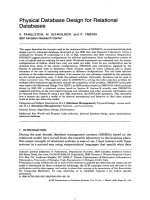
Figure 3-15 shows a data diagram with authors on the right of the diagram and their respective publica-
tions on the left, in a one-to-many relationship. One author has two titles, another five titles, another
three titles, two authors have one each, and two other authors have nothing published at all— at least
not in this database.
Figure 3-15: One-to-many implies one entry to many entries between two tables.
Many-to-Many
A many-to-many relationship means that for every one record in one table there are many possible records
in another related table, and visa versa (for both tables). The classic example of a many-to-many relation-
ship is many students enrolled in many courses at a university. The implication is that every student is
registered for many courses and every course has many students registered. The result is a many-to-
many relationship between students and courses. This is not a problem as it stands; however, if an appli-
cation or end-user must find an individual course taken by an individual student, a uniquely identifying
table is required. Note that this new table is required only if unique items are needed by end-users or an
application.
In Figure 3-16, from left to right, the many-to-many relationship between
PUBLISHER and PUBLICATION
tables is resolved into the EDITION table. A publisher can publish many publications and a single publi-
cation can be published by many publishers. Not only can a single publication be reprinted, but other
types of media (such as an audio tape version) can also be produced. Additionally those different ver-
sions can be produced by different publishers. It is unlikely that a publisher who commissions and
prints a book will also produce an audio tape version of the same title. The purpose of the
EDITION table
is to provide a way for each individual reprint and audio tape copy to be uniquely accessible in the
database.
1
2
3
4
5
6
7
9
10
11
8
12
7
7
7
7
7
7
7
7
7
7
15
16
2
2
3
3
3
3
3
4
4
4
6
7
Cities in Flight
A Case of Conscience
Foundation
Second Foundation
Foundation and Empire
Foundation’s Edge
Prelude to Foundation
Lucifer’s Hammer
Footfall
Ringworld
The Complete Works of Shakespeare
Hocus Pocus
PUBLICATION_ID SUBJECT_ID AUTHOR_ID TITLE
1
5
6
Orson Scott Card
James Blish
Isaac Azimov
Larry Niven
Jerry Pournelle
William Shakespeare
Kurt Vonnegut
AUTHOR_ID NAME
2
3
4
7
53
Database Modeling Building Blocks
07_574906 ch03.qxd 11/4/05 10:48 AM Page 53
Figure 3-16: Resolving a many-to-many relationship.
In Figure 3-17 there are seven different editions of the publication Foundation. How is this so? Isaac
Azimov is an extremely popular author who wrote books for decades. This particular title was written
many years ago and has been in print ever since. Searching for this particular publication without the
unique ISBN number unique to each edition would always find seven editions in this database. If only
one of the Books On Tape editions was required for a query, returning seven records rather than only one
could cause some serious problems. In this case, a many-to-many join resolution table in the form of the
EDITION table is very much needed.
Publisher
publisher_id
name
Publisher
publisher_id
name
Publication
publication_id
subject_id
author_id
title
Publication
publication_id
subject_id
author_id
title
Edition
ISBN
publisher_id (FK)
publication_id (FK)
print_date
pages
list_price
format
rank
ingram_units
Many-to-many implies a publisher
can publish many books and a
single book can be published by
many publishers, when assuming
multiple editions for a single book
The Edition entity
resolves books
published more
than once, by
different publishers
54
Chapter 3
07_574906 ch03.qxd 11/4/05 10:48 AM Page 54
Figure 3-17: Resolving a many-to-many relationship.
Zero, One, or Many
Relationships between tables can be zero, one, or many. Zero implies that the record does not have
to exist in the target table; one with zero implies that it can exist; one without zero implies that it must
exist; and many simply implies many. The left side of Figure 3-18 shows a one-to-zero (or exactly one)
relationship between the
RANK and EDITION tables. What this implies is that an EDITION record does
not have to have a related
RANK record entry. Because the zero is pointing at the RANK table, however, the
same is not the case in reverse. In other words, for every
RANK entry, there must be exactly one record
in the
EDITION table; therefore, individual editions of books do not have to be ranked, but a ranking
requires a book edition to rank. There is no point having a ranking without having a book to rank—
in fact, it is impossible to rank something that does not exist.
Similarly, on the right side of Figure 3-18, a publisher can be a publisher, if only in name, even if that
publisher currently has no books published. When you think about that, in reality it sounds quite silly
to call a company a publisher if it has no publications currently produced. It’s possible, but unlikely.
However, this situation does exist in this database as a possibility. For example, a publisher could be
bankrupt where no new editions of its books are available, but used editions of its books are still available.
This does happen. It has happened.
1585670081
345438353
246118318
5553673224
5557076654
345334787
345308999
893402095
345336275
553293362
553293370
553293389
553298398
449208133
345323440
345333926
Overlook Press
Ballantine Books
HarperCollins Publishing
Books on Tape
Books on Tape
Del Rey Books
Del Rey Books
L P Books
Ballantine Books
Bantam Books
Spectra
Spectra
Spectra
Fawcett Books
Del Rey Books
Ballantine Books
Cities in Flight
A Case of Conscience
Foundation
Foundation
Foundation
Foundation
Foundation
Foundation
Foun
dation
Second Foundation
Foundation and Empire
Foundation’s Edge
Prelude to Foundation
Lucifer’s Hammer
Footfall
Ringworld
ISBNPUBLISHERTITLE PRINTED
28-Apr-83
31-Jan-20
31-Dec-85
31-Jan-51
28-Feb-83
31-May-79
31-Jul-86
31-May-85
31-Jul-96
30-Nov-90
Each edition is
uniquely identified
by ISBN – unique
to each new edition
of the same title
55
Database Modeling Building Blocks
07_574906 ch03.qxd 11/4/05 10:48 AM Page 55
Figure 3-18: One implies a record must be present and zero the record can be present.
Figure 3-19 shows the equivalent of the one-to-one table structure representation using similar but a
little more data than the data in Figure 3-13. ISBNs 198711905 and 345308999 both have
RANK and
INGRAM_UNITS value entries and thus appear in the RANK table as unique records. On the contrary, the
edition with ISBN 246118318 does not have any information with respect to rank and Ingram unit values,
and thus
RANK and INGRAM_UNITS field values would be NULL valued for this edition of this book. Since
values are
NULL valued, there is no record in the RANK table for the book with ISBN 246118318.
Publisher
publisher_id
name
Publication
publication_id
subject_id
author_id
title
Rank
ISBN (FK)
rank
ingram_units
Edition
ISBN
publisher_id (FK)
publication_id (FK)
print_date
pages
list_price
format
rank
ingram_units
Edition
ISBN
publisher_id
publication_id
print_date
pages
list_price
format
One to zero, one or many
An edition does not have
to be ranked but if a Rank
row exists there must be
a related edition
Zero or one to
exactly one
56
Chapter 3
07_574906 ch03.qxd 11/4/05 10:48 AM Page 56
Figure 3-19: One implies a record must be present and zero the record can be present.
Identifying and Non-Identifying Relationships
Figure 3-20 shows identifying relationships, non-identifying relationships, and dependent tables. These
factors are described as follows:
❑ Identifying relationship— The child table is partially identified by the parent table, and partially
dependent on the parent table. The parent table primary key is included in the primary key of
the child table. In Figure 3-20, the
COAUTHOR table includes both the AUTHOR and PUBLICATION
primary keys in the COAUTHOR primary key as a composite of the two parent table fields.
❑ Non-identifying relationship— The child table is not dependent on the parent table such that
the child table includes the parent table primary key as a foreign key, but not as part of the child
table’s primary key. Figure 3-20 shows a non-identifying relationship between the
AUTHOR and
PUBLICATION tables where the PUBLICATION table contains the AUTHOR_ID primary key field
from the
AUTHOR table. However, the AUTHOR_ID field is not part of the primary key in the
PUBLICATION table.
❑ Dependent entity or table — The
COAUTHOR table is dependent on the AUTHOR and PUBLICATION
tables. A dependent table exists for a table with an identifying relationship to a parent table.
❑ Non-dependent entity or table — This is the opposite of a dependent table.
198711905
345308999
345306275
345438353
553278398
553293362
553293370
553293389
893402095
1585670081
5557076654
1150
1200
1800
2000
1900
1050
1950
1100
1850
1000
1250
130
140
ISBN RANK INGRAM_UNITS
Rank
Rank
Edition
Edition
198711905
246118318
345308999
345323440
345333926
345334787
345336275
345338353
449208133
553278398
553293362
1150
1200
1800
2000
1900
1050
1950
1100
1850
1000
1250
ISBN RANK INGRAM_UNITS
553293370
553293389
893402095
1585670081
5553673224
5557076654
Hardcover
Hardcover
Paperback
Paperback
Paperback
Paperback
Paperback
Paperback
Hardcover
AudioCassette
AudioCassette
Non-highlighted
editions do not
have rankings
57
Database Modeling Building Blocks
07_574906 ch03.qxd 11/4/05 10:48 AM Page 57
Figure 3-20: Identifying, non-identifying, and dependent relationships
Keys are used to identify and ultimately retrieve records from a database at a later date.
Understanding Keys
Relational databases use the terms index and key to indicate similar concepts. An index is like an index
in a book — used to find specific topics, on specific pages, in a book, very quickly (without having to
read the entire book). Similarly, an index in a relational database is a copy of a part of a table, perhaps
structured in a specific format such as a BTree index. An index can be created on any field in a table. A
key, on the other hand, is more of a concept than a physical thing because a key is also an index. In a
relational database, however, a key is a term used to describe the fields in tables linking tables together
to form relationships (such as a one-to-many relationship between two tables).
A key is both a key and an index. A key is an index because it copies fields in a table into a more efficient
searching structure. A key is also a key, its namesake, because it creates a special tag for a field, allowing
that field to be used as a table relationship field, linking tables together into relations. There are three
types of keys: a primary key, a unique key, and a foreign key.
Author
author_id
name
Publication
publication_id
subject_id
author_id (FK)
title
CoAuthor
coauthor_id (FK)
publication_id (FK)
Dependent entity is a
rounded rectangle shape
Parent primary keys
part of primary key
Identifying relationship
– Coauthor uniquely
identified by Author
and Publication
Non identifying
relationship –
Publication not
uniquely identified
by Author
Parent primary
keys not part
of primary key
Independent entity
is not rounded
58
Chapter 3
07_574906 ch03.qxd 11/4/05 10:48 AM Page 58
Primary Keys
A primary key is used to uniquely identify a record in a table. Unique identification for each record is
required because there is no other way to find a record without the possibility of finding more than one
record, if the unique identifier is not used. Figure 3-21 shows primary key fields of
AUTHOR_ID for the
AUTHOR table and PUBLICATION_ID for the PUBLICATION table, each being primary key fields for
the two tables.
Figure 3-21: A primary key uniquely identifies a record in a table.
Unique Keys
Like a primary key, a unique key is created on a field containing only unique values throughout an entire
table. In Figure 3-21, and throughout the rest of this chapter, you may be wondering why integers are
used as primary keys rather than the name of an author or a publication, and otherwise. The reason why
will be explained later in this book but in general integer value primary keys are known as surrogate keys
because they substitute as primary keys for names.
For example, the
AUTHOR_ID field in the AUTHOR table is a surrogate primary key as a replacement or
surrogate for creating the primary on the
AUTHOR table NAME field, the full name of the author. It is very
unlikely that there will be two authors with the same name. Surrogate keys are used to improve
performance.
So, why create unique keys that are not primary keys? If surrogate keys are used and the author name is
required to be unique, it is common to see unique keys created on name fields such as the
AUTHOR table
NAME and the PUBLICATION table TITLE fields. A unique key ensures uniqueness across a table. A
primary key is always unique, or at least a unique key; however, a primary key is also used to define
relationships between tables. Unique keys are not used to define relationships between tables.
1
2
3
4
5
6
7
8
9
10
11
12
2
2
3
3
3
3
3
4
4
4
6
7
Cities in Flight
A Case of Conscience
Foundation
Second Foundation
Foundation and Empire
Foundation’s Edge
Prelude to Foundation
The Complete Works of Shakespeare
Lucifer’s Hammer
Footfall
Ringworld
Hocus Pocus
PUBLICATION_ID AUTHOR_ID TITLE
1
5
6
Orson Scott Card
James Blish
Isaac Azimov
Larry Niven
Jerry Pournelle
William Shakespeare
Kurt Vonnegut
AUTHOR_ID NAME
2
3
4
7
Publication
Publication
Author
Author
Author
author_id
name
Publication
publication_id
subject_id (FK)
author_id (FK)
title
PUBLICATION_ID uniquely
identifies a publication
AUTHOR_ID uniquely
identifies an author
59
Database Modeling Building Blocks
07_574906 ch03.qxd 11/4/05 10:48 AM Page 59
The AUTHOR table could be created with a simple script such as the following:
CREATE TABLE Author
(
author_id INTEGER NOT NULL,
name VARCHAR(32) NULL,
CONSTRAINT XPK_Author PRIMARY KEY (author_id),
CONSTRAINT XUK_A_Name UNIQUE (name)
);
In this script, the primary key is set to the AUTHOR_ID field and the name of the author is set to be
unique to ensure that the same author is not added twice, or that two authors do not use the same
pseudonym.
Foreign Keys
Foreign keys are the copies of primary keys created into child tables to form the opposite side of the link in
an inter-table relationship — establishing a relational database relation. A foreign key defines the reference
for each record in the child table, referencing back to the primary key in the parent table.
Figure 3-22 shows that the
PUBLICATION table has a foreign key called AUTHOR_ID (FK). This means that
each record in the
PUBLICATION table has a copy of the parent table’s AUTHOR_ID field value, the AUTHOR
table primary key value, in the AUTHOR_ID foreign key field on the PUBLICATION table. In other words,
an author can have many books published and available for sale at once. Similarly, in Figure 3-22, the
COAUTHOR table has a primary key made up of two fields, which also happens to comprise the combination
or composite of a two foreign key relationship back to both the
AUTHOR table and the PUBLICATION table.
The
PUBLICATION table could be created with a simple script such as the following:
CREATE TABLE Publication
(
publication_id INTEGER NOT NULL,
subject_id INTEGER NOT NULL,
author_id INTEGER NOT NULL,
title VARCHAR(64) NULL,
CONSTRAINT XPK_Publication PRIMARY KEY (publication_id),
CONSTRAINT FK_P_Subject FOREIGN KEY (subject_id) REFERENCES Subject,
CONSTRAINT FK_P_Author FOREIGN KEY (author_id) REFERENCES Author,
CONSTRAINT XUK_P_Title UNIQUE (title)
);
In this script, the primary key is set to the PUBLICATION_ID field. The fields SUBJECT_ID and
AUTHOR_ID are set as two foreign key reference fields to the SUBJECT and AUTHOR tables, respectively.
A unique key constraint is applied to the title of the publication, ensuring copyright compliance.
60
Chapter 3
07_574906 ch03.qxd 11/4/05 10:48 AM Page 60
Figure 3-22: A foreign key is used to link back to the primary key of a parent table.
There will be more explanation of the how and why of primary and foreign keys Chapter 4. At this
point, simply remember that a primary key uniquely identifies each record in a table. A foreign key is a
copy of the primary key copied from a parent table, establishing a relationship between parent and child
tables. A unique key simply ensures the uniqueness of a value within a table.
Try It Out Creating Some Simple Tables
Figure 3-23 shows some data. Do the following exercise:
1. Create two related tables linked by a one-to-many relationship.
2. Assign a primary key field in each table.
3. Assign a foreign key field in one table.
1
2
3
4
5
6
7
Orson Scott Card
James Blish
Isaac Azimov
Larry Niven
Jerry Pournelle
William Shakespeare
Kurt Vonnegut
AUTHOR_ID NAME
1
2
3
4
5
6
7
AUTHOR_ID
1
2
3
4
5
6
7
Cities in Flight
A case of Conscience
Foundation
Second Foundation
Foundation and Empire
Foundation’s Edge
Prelude to Foundation
4
7
Lucifer’s Hammer
Footfall
Ringworld
The Complete Works of Shakespeare
PUBLICATION_ID NAME
11
12
Jerry Pournelle
Jerry Pournelle
COAUTHOR
5
5
COAUTHOR_ID PUBLICATION_ID
Footfall
Lucifer’s H ammer
TITLE
4
4
9
10
9
10
Author
author_id
name
Publication
publication_id
subject_id (FK)
author_id (FK)
title
CoAuthor
coauthor_id (FK)
publication_id (FK)
61
Database Modeling Building Blocks
07_574906 ch03.qxd 11/4/05 10:48 AM Page 61
Figure 3-23: Band names, tracks, and silly descriptions.
How It Works
You are asked for two tables from three fields. One table has one field and the other table has two fields.
The three fields are conveniently arranged. Look for a one-to-many relationship by finding duplicated
values. The data is inconveniently and deliberately unsorted.
1. The first column contains the names of numerous different bands (musical groups) and the
second column a track or song name. Typically, different bands or musical groups create many
tracks. A one-to-many relationship exists between the band names and track names.
2. Band names in the first column are duplicated. Track names and descriptions are not. This
supports the solution already derived in step 1.
3. Band names are the only duplicated values, so they make up the table on the parent side of the
one-to-many relationship. The other two columns make up the table on the child side of the
relationship.
4. The track name must identify the track uniquely. The description is just silly.
Figure 3-24 shows three viable solutions with Option 3 being the better of all of the three options because
surrogate keys are used for the primary and foreign keys. Option 2 is better than Option 1 because in
Option 2 the one-to-many relationship is a non-identifying relationship, where the primary key on the
TRACK table is not composite key.
Nirvana
Nirvana
Nirvana
Nirvana
Stone Temple Pilots
Greetings From Limbo
Greetings From Limbo
Pearl Jam
Pearl Jam
Pearl Jam
Foo Fighters
Greetings From Limbo
Red Hot Chili Peppers
Red Hot Chili Peppers
Red Hot Chili Peppers
Red Hot Chili Peppers
Soundgarden
Red Hot Chili Peppers
Red Hot Chili Peppers
Come As You Are
About A Girl
The Man Who Sold The World
Polly
The Right Line
Greetings From Limbo
Fatal
Immortality
Around The Bend
Ashes
My Friends
Suck My Kiss
University Speaking
Under The Bridge
Otherside
Californication
Bass reverb
Lots of lovely bass
Sell out!
Who’s that?
Country groove
The Wizard of Oz
Deadly
Just imagine
Nuts!
Heavy
Hmmm
No thanks
OK
Where’s that confounded bridge?
Hmmm again
Hot and dry
BAND NAME TRACK DESCRIPTION
62
Chapter 3
07_574906 ch03.qxd 11/4/05 10:48 AM Page 62
Figure 3-24: Band names, tracks, and silly descriptions represented as an ERD.
Understanding Referential Integrity
Referential Integrity functions just as its name states: It ensures the integrity of referential relationships
between tables as defined by primary and foreign keys. In a relation between two tables, one table has
a primary key and the other a foreign key. The primary key uniquely identifies each record in the first
table. In other words, there can be only one record in the first table with the same primary key value.
The foreign key is placed into the second table in the relationship such that the foreign key contains a
copy of the primary key value from the record in the related table.
Band
band_name
Track
band_name (FK)
track_name
description
Option 1
Option 1
Band
band_name
Track
band_name (FK)
description
track_name
Option 2
Option 2
Band
band_id
band_name
Track
band_id (FK)
track_name
description
track_id
Option 3
Option 3
Primary key is
a composite -
inefficient
Primary keys are
names – large key
values - inefficient
Surrogate keys
used - efficient
63
Database Modeling Building Blocks
07_574906 ch03.qxd 11/4/05 10:48 AM Page 63
So, what is Referential Integrity? Referential Integrity ensures the integrity of relationships between pri-
mary and foreign key values in related tables. Most relational database engines use what are often called
constraints. Primary and foreign keys are both constraints. Remember, a constraint is a piece of metadata
defined for a table defining restrictions on values. A primary key constraint forces the primary key field
to be unique. A primary key constraint is also forced to make checks against any foreign key constraints
referenced back to that primary key constraint. Referencing (or referential) foreign key constraints can be
in any table, including the same table as the primary key constrained field referenced by the foreign key
(a self join). A foreign key constraint uses its reference to refer back to a referenced table, containing the
primary key constraint, to ensure that the two values in the primary key field and foreign key field
match.
Simply put, primary and foreign keys automatically verify against each other. Primary and foreign key
references are the connections establishing and enforcing Referential Integrity between tables. There are
some specific circumstances to consider in terms of how Referential Integrity is generally enforced:
A primary key table is assumed to be a parent table and a foreign key table a child table.
❑ When adding a new record to a child table, if a foreign key value is entered, it must exist in the
related primary key field of the parent table.
Foreign key fields can contain
NULL values. Primary key field values can never contain NULL values as
they are required to be unique.
❑ When changing a record in a parent table if the primary key is changed, the change must be
cascaded to all foreign key valued records in any related child tables. Otherwise, the change to
the parent table must be prohibited.
The term “cascade” implies that changes to data in parent tables are propagated to all child tables
containing foreign key field copies of a primary key from a parent table.
❑ When changing a record in a child table, a change to a foreign key requires that a related
primary key must be checked for existence, or changed first. If a foreign key is changed to
NULL,
no primary key is required. If the foreign key is changed to a non-
NULL value, the foreign key
value must exist as a primary key value in the related parent table.
❑ When deleting a parent table record then related foreign key records in child tables must either
be cascade deleted or deleted from child tables first.
Understanding Indexes
Indexes are not really part and parcel of the relational database model itself; however, indexes are so
important to performance and overall database usability that they simply have to be introduced
without going into the nitty-gritty of how each different type of index functions internally. It is important
to understand the fundamentals of indexes and their different types and attributes to get a basic
understanding as to why exactly indexing is so important for relational databases in general.
64
Chapter 3
07_574906 ch03.qxd 11/4/05 10:48 AM Page 64
What Is an Index?
An index is usually and preferably a copy of a very small section of table, such as a single field, and
preferably a short length field. The act of creating an index physically copies one or more fields to be
indexed into a separate area of disk other than that of the table. In some databases, indexes can be stored
in a file completely separated from that of the table. Different databases are structured differently on
a physical level. The important factor is the underlying physical separation. When a table is accessed, a
process usually called an Optimizer decides whether to access the table alone, scanning all the records in the
table, or if it is faster to read the much smaller index in conjunction with a very small section of the table.
All relational databases have some type of SQL execution optimization process. It is usually called the
Optimizer.
An index essentially behaves like an index in the back of a book or the table of contents at the front of a
book. When searching for details on a specific topic, it is much easier to find the term in the index or
table of contents first, and then use a page reference number to find the information within the pages of
the text. Reading the entire book every time you want to find a definition for a single term would be far
too time-consuming to be useful, probably making the book completely useless as a reference. Most
technical books are used as reference guides in one form or another.
Following are some things to be avoided when indexing:
❑ Creating too many indexes—Too many indexes on a table can result in very slow database change
responses. This is because every change to a table updates every index attached to it, as well as the
table. The more indexes created for a table, the more physical changes are required.
❑ Indexing too many fields — Indexing too many fields not only makes the use of the indexes by
queries more complex, but also makes the indexes too large physically. An index must be
relatively much smaller than a table, and should be created on as few fields from that table as
is possible.
Alternate Indexing
Alternate indexing really comes from the terms “alternate index,” “secondary index,” “tertiary index,” or
just plain “indexing.” Specific use of terminology depends on the database in use. These terms all mean
the same thing. Alternate indexes are an alternate to the primary relational structure organized by
primary and foreign key indexes. Alternate indexes are alternate because they are in addition to primary
and foreign key indexes and exist as alternate sorting methods to those provided by primary and foreign
keys. By definition, the unique key indexes described in a previous section of this chapter are essentially
alternate indexes, as well as being unique constraints.
Foreign Key Indexing
Relationships between tables such as that between the AUTHOR and PUBLICATION tables shown in Figure
3-21 can allow the foreign key in the child table not only to be duplicated (one-to-many) but also to be
NULL
valued in the child table (one-to-zero, one or many). In other words, in Figure 3-21, each author can have
multiple publications or an author does not have to have any publications at all. Because foreign keys are
allowed to be
NULL valued and do not have to be unique, indexes must be created on those foreign key
fields manually.
65
Database Modeling Building Blocks
07_574906 ch03.qxd 11/4/05 10:48 AM Page 65
Because primary keys must be unique, a relational database should automatically create internal unique
indexes on primary keys.
Commands similar to the following commands could be used to create indexes on foreign key fields, for
the
CREATE TABLE command on the PUBLICATION table shown previously in this chapter:
CREATE INDEX XFK_P_Author ON Publication(author_id);
CREATE INDEX XFK_P_Publisher ON Publication(subject_id);
Types of Indexes
It is important to have a brief understanding of different types of indexing available in relational
databases. Some of the smaller-scale database engines (such as dBase, Paradox, and MS Access) might
offer little or no variation on index types allowed, generally using BTree type indexing. Types of indexes
in various relational database engines are as follows:
❑ BTree index — BTree means “binary tree” and, if drawn out on a piece of paper, a BTree index
looks like an upside down tree. The tree is called “binary” because binary implies two options
under each branch node: branch left and branch right. The binary counting system of numbers
contains two digits, namely 0 and 1. The result is that a binary tree only ever has two options as
leafs within each branch — at least that is the theory, not being precisely the case in all databases.
BTree indexes are sometimes improperly named as they are not actually binary meaning two —
branches can have more than two leafs contained within them. Naming conventions are largely
immaterial in this situation. Essentially, a BTree consists of a root node, branch nodes, and
ultimately leaf nodes containing the indexed field values in the ending (or leaf) nodes of the tree.
Some BTree construction and searching methods in some databases are highly efficient for both
reading and changing of data, automatically changing the structure of the BTree index without
any overflow.
Overflow is bad for indexing because changes are placed outside of the optimized index structure.
Enough changes and overflow can destroy the efficiency of an index, eventually rendering it useless and
drastically deteriorating rather than generally improving table access performance.
Figure 3-25 shows an example of what a typical relational database BTree index might look like.
❑ Bitmap index — A Bitmap index contains binary representations for each record using 0’s and 1’s.
Bitmap indexes are often misused and are extremely vulnerable to overflow over long periods
of time. Values cannot be slotted into the existing Bitmap index structure as readily as can be
done when updating a BTree index. Figure 3-26 shows a graphical type structure of the internal
machinations of a Bitmap index where two bitmaps are created for two values of M for male
and F for female. When M is encountered, the M bitmap is set to 1 and the F bitmap is set to 0.
In general, Bitmap indexes can be disappointing, even in environments where they are suppos-
edly highly beneficial.
66
Chapter 3
07_574906 ch03.qxd 11/4/05 10:48 AM Page 66
Figure 3-25: A BTree index.
Figure 3-26: A Bitmap index.
Name
Chris
Laura
Tina
Lance
Christina
Craig
Sex is M
1
0
0
1
0
1
Sex is F
Bitmap
0
1
1
0
1
0
M for Male
is set to 1
F for Female
is set to 1
Ca Jo T
A B Be Ca E Je Jo T
Leaf Block
Leaf Block
Leaf Block
Leaf Block
Leaf Block
Leaf Block
Leaf Block
Leaf Block
Leaf Block
Leaf Block
Leaf Block
Leaf Block
Leaf Block
Leaf Block
Leaf Block
Leaf Block
Leaf Block
Leaf Block
Leaf Block
Leaf Block
Leaf Block
Root node
Branch nodes
Indexed values
+ a pointer to
each table row
Values to
left of Ca
Values to
right of Ca
67
Database Modeling Building Blocks
07_574906 ch03.qxd 11/4/05 10:48 AM Page 67
❑ ISAM index — Indexed Sequential Access Method (ISAM) uses a simple structure with a list of
record numbers. ISAM indexes are used in various database engines. ISAM indexes are best
used for static data as their internal list structure prohibits easy changes, making them
extremely vulnerable to index overflow.
❑ Hash table — A hash table is a copy of data but rearranged into a different and more efficiently
accessed order depending on a hashing algorithm. For example, a hashing algorithm takes a
string and creates a number from that string. The number created by a specific string is always
the same and is thus placed in a position in an index, sorted based on the hash-calculated value.
Hash indexes can be highly efficient for read access, but are best avoided when subjected to any
kind of data changes. Hash tables are likely to overflow worse than Bitmap indexes because
there is absolutely no scope whatsoever for changes. The only way to push record changes from
table to index is by regenerating the entire hash table index.
❑ Index Organized Table — An Index Organized Table (IOT) builds a table in the sorted order of an
index, typically using a BTree index. IOTs can actually work fairly well in many types of
databases, but you must remember that index record length is much longer than normal
because index leaf blocks contain all fields in the entire record length of a table. Also, if the IOT
is not read in indexed order, obviously all records in the table are read, and thus the index is
ignored. Because the table is built in the structure of an index, however, not reading the table in
IOT indexed order could be seriously problematic for performance.
Different Ways to Build Indexes
Indexes can usually be built in various different ways to accommodate however they might be used. Once
again, some relational databases allow all of these options, some allow some, and some allow none.
❑ Ascending or descending index — An index can be built sorted in a normally ascending order
(such as A, B, C) or in descending order (such as C, B, A).
❑ Unique index — Indexes values must be unique (can’t contain duplicate values).
❑ Non-unique index — Non-unique indexes contain duplicated or repeated values in the index.
It is normal to create both unique indexes and non-unique indexes.
❑ Composite index — Indexes can be built on more than a single field and are known as composite
field indexes, multiple field indexes, or just plain old composite indexes. The most efficient type
of index is a single field index containing an integer.
❑ Compressed indexes— Some databases allow compression of composite indexes where repeated
prefix values are effectively indexed within the index, removing duplications within prefixed
indexed fields. In other words, a composite index containing three fields can be accessed using
a single value of the first field.
❑ Reverse key indexes — This is a really weird and unusual one. Only a very select few databases
allow building of indexes such that indexed field values are stored as reverse strings. When
adding gazillions of records at once to the same index in a very busy database, adding sequen-
tial index values (not reversed) adds many records all at once to the same physical space in the
index. The result is what some relational databases call locking and other relational databases
68
Chapter 3
07_574906 ch03.qxd 11/4/05 10:48 AM Page 68
call hot blocking. The result is the same— gridlock! Reverse keys make the index values not
sequential in terms of where they are physically written to disk. The result is no locking, no hot
blocking, no gridlock, and, thus, much better performance.
Other than tables, keys, and indexes, there are other types of objects. These other object types are more eas-
ily defined as data management objects and only loosely definable as data modeling objects. Management
of data is the administration process occurring on a production system, long after completion of the data
modeling process.
Introducing Views and Other Specialized
Objects
So far in this chapter, topics covered have included tables, relationships between tables, and indexes
attached to tables. You should understand the basic structure of a table, and that the relationships
between tables are determined by primary keys in parent tables linked to foreign keys in child tables.
Foreign keys are copies of primary key field values from parent tables. Indexing is important to under-
stand not directly from a modeling perspective, but that indexes are used to superimpose a different
order on top of the order created by the very structure of the relationships between tables, imposed by
primary and foreign keys.
Other than all these wonderful indexing things, there are further possibilities within relational databases
that some database engines allow and some do not. It is important to know that specialized objects exist
as options for expansion to a relational database model, as extensions to both the underlying physical
structure of a database and the overlying logical structure (the tables and indexes). Following are a few
examples:
❑ Views — A view is essentially a query definition and does not contain any data. A view is not a
physical copy of data and does not contain any data itself. A view is merely a logical overlay of
existing tables. Every execution against a view executes the query contained within the view
against all underlying tables. The danger with using views is filtering a query against a view,
expecting to read a very small portion of a very large table. Any filtering should be done within
the view because any filtering against the view itself is applied after the query in the view has
completed execution. Views are typically useful for speeding up the development process but
in the long run can completely kill database performance.
❑ Materialized views — Materialized views are available in some very large capacity type relational
databases. A materialized view materializes underlying physical data by making a physical
copy of data from tables. So, unlike a view as described previously, when a query is executed
against a materialized view, the materialized view is physically accessed rather than the
underlying tables. The objective is to free the underlying tables for other uses, effectively creating
two separate physical copies. Materialized views are often used to aggregate large data sets
down to smaller sized data sets, in data warehouses and data marts. The biggest potential
problem with materialized views is how often they are refreshed and brought up to date with
any changes to their underlying tables. Another attribute of materialized views is the ability of
some database engines to allow a query directed at an underlying table to be automatically
redirected to a physically much smaller materialized view, sometimes called automated query
rewrite. Queries can be automatically rewritten by the query Optimizer if the query rewrite can
help to increase query performance.
69
Database Modeling Building Blocks
07_574906 ch03.qxd 11/4/05 10:48 AM Page 69
❑ Clusters — Clusters are used in very few databases and have been somewhat superceded by
materialized views. In the past, clusters were used to pre-create physical copies of entire field
level sections of heavily accessed tables, especially in SQL joins. Unlike materialized views,
clusters do not allow for automatic refresh and are normally manually maintained.
❑ Sequences and auto counters — An auto counter field is a special datatype, sometimes called a
non-static internal function, allowing automated generation of sequential number values (thus the
term “sequence”). Typically, auto counters are used for primary key surrogate key generation on
insertion of new records into a table.
❑ Partitioning and parallel processing— Some databases allow physical splitting of tables into
separate partitions, including parallel processing on multiple partitions and individual opera-
tions on individual partitions. One particularly efficient aspect of partitioning is the capability
when querying a table to read fewer than all the partitions making up a table, perhaps even a
single partition.
Summary
In this chapter, you learned about:
❑ Building tables containing fields, datatypes, and simple validation
❑ The different types of relationships between tables
❑ Representing relations in ERDs
❑ Defining referential integrity relationships between tables using primary and foreign keys
❑ The types and uses of indexes
❑ The types and uses of specialized objects such as views, materialized views, and auto counters
The next chapter discusses the very heart of the relational database model by examining the process of
normalization through the application of normal forms.
Exercises
1. Write two CREATE TABLE commands for the tables in Option 3 of Figure 3-24. Make sure that all
primary key, foreign key, and any potentially necessary unique keys are included.
2. Write CREATE INDEX commands to create all indexes on any foreign keys indicated in the
CREATE TABLE command written for the previous question.
70
Chapter 3
07_574906 ch03.qxd 11/4/05 10:48 AM Page 70
Part II
Designing Relational
Database Models
In this Part:
Chapter 4: Understanding Normalization
Chapter 5: Reading and Writing Data with SQL
Chapter 6: Advanced Relational Database Modeling
Chapter 7: Understanding Data Warehouse Database Modeling
Chapter 8: Building Fast-Performing Database Models
08_574906 pt02.qxd 10/28/05 11:43 PM Page 71
08_574906 pt02.qxd 10/28/05 11:43 PM Page 72