Character Animation with Direct3D- P7 pdf
Bạn đang xem bản rút gọn của tài liệu. Xem và tải ngay bản đầy đủ của tài liệu tại đây (642.03 KB, 20 trang )
106 Character Animation with Direct3D
How is the difference in size between actors and models handled?
JN: Basically, there are no limits there at all. We have even had a human actor do the
motions for a T-Rex once. You will, of course, have to make adjustments if you record
a very small person and use the recorded motions for a large game character. Often
small people and large people move completely different. Another funny thing is that
you can really see from the motion whether the actor is a woman or a man. One time
we tried to capture motion for a 3D character, a woman, and I was acting. That’s
actually somewhat of an inside joke here now. An outsider came to look at the final
animation and he immediately said that it has got to be a man.
JM: That’s the cool accuracy of this system. If you know the actor personally, you can
see that it is him or her just from watching the motion capture data. There’s more
emotion in movements than you might think, and you can really see the difference
when you compare motion capture animation to traditional artist created animation.
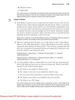
FIGURE 5.9
Mocap with actor jumping.
Please purchase PDF Split-Merge on www.verypdf.com to remove this watermark.
CONCLUSIONS
In this chapter you learned about some more advanced topics of character
animation. You learned about animation blending, which is something you’ll
definitely need if you ever aim to create a realistic character. With it, you can
create new animations by blending two others together. You can also create a
transition between two animations by blending between them. Another advanced
topic covered in this chapter was animation callbacks, with which you can time
events in your game to when a specific animation occurs. If you made a fighting
game for instance, you might want to time the “punch” sound to a specific time
in the punch animation. Lastly, the topic of motion capture and its variations
were briefly covered. That about wraps up the skeletal animation part of
this book, which the last three chapters have focused on. Now it’s time to turn to
dynamic animation and look at implementing a ragdoll system.
CHAPTER 5 EXERCISES
Try modifying Example 5.1 so that you run the same animation in two different
tracks, with different weights and slightly different speeds. See what happens?
Create animation callbacks for the footsteps in the Soldier’s walk animation.
FURTHER READING
[1]
[2]
[3]
[4]
Chapter 5 Advanced Skeletal Animation Techniques 107
Please purchase PDF Split-Merge on www.verypdf.com to remove this watermark.
This page intentionally left blank
Please purchase PDF Split-Merge on www.verypdf.com to remove this watermark.
109
Physics Primer6
As is common practice with most programming books that include only one chapter
covering physics, I’ll start this one with a disclaimer. This book is not about physics!
There are books focusing solely on the topic of game physics. However, since I will be
covering ragdoll animations in this book, I need cover the “bare bones,” so to speak,
of creating a physics engine. The physics engine demonstrated in this chapter builds
on simulating particles connected with springs. In this chapter you’ll learn about the
following topics:
Please purchase PDF Split-Merge on www.verypdf.com to remove this watermark.
Basics of rigid body physics
Quaternions
Oriented bounding boxes
Intersection tests
Simulating a particle
Simulating a spring
In the beginning of this chapter, many basic physical concepts will be covered. If you
are already comfortable with Newton’s three laws of motion, gravity, quaternions,
etc., feel free to skip ahead to the implementation part at the end of this chapter.
INTRODUCTION TO RIGID BODY PHYSICS
If you’ve never come across the topic of rigid bodies before, don’t worry; it is quite
easy to understand (even though it can be quite hard to simulate). A rigid body is by
definition a solid mass in space that does not change shape. A real-life basketball is
an example of a non-rigid body. The fact that the basketball is not rigid is what
causes it to bounce once it hits the floor. Instead, imagine a sphere the size of a
basketball in solid steel hitting a steel floor. Very likely there wouldn’t be a very large
bounce from a collision like this. This is because the steel sphere won’t change its
shape. It is rigid!
In computer graphics there are accurate mathematical systems where rigid
bodies are simulated colliding with the environment and with each other. In
games, however, this simulation has to be able to run in real time. This essentially
means several shortcuts need to be taken, and some serious optimizations must be
done in order to get it fast enough for real-time applications. So when making
physics engines for games, things like speed, stability, and appearance take prece-
dence over accuracy and realism.
Before I dive into rigid body physics, I’ll cover the basics of physics in general.
Over 300 years ago a fellow named Isaac Newton published a three-volume work
called Philosophiae Naturalis Principia Mathematica, or Principia for short. In
plain English, the title was “Mathematical Principles of Natural Philosophy” and
contained, as you may already know, Newton’s three laws of motion. The first of
the three volumes was called De motu corporum (“On the motion of bodies”), and
now, more than 300 years later, these laws are still used when simulating physics
in games. Table 6.1 shows a simplified version of Newton’s laws of motion.
110
Character Animation with Direct3D
Please purchase PDF Split-Merge on www.verypdf.com to remove this watermark.
The second law can also be described with the famous formula:
F = ma or a =
F
m
The force equals the mass of an object times its acceleration. However, more
often you are interested in the acceleration resulting from an external force, in which
case the acceleration a is the force F divided by an object’s mass m. Later on I’ll dis-
cuss how the acceleration of an object affects its velocity and its position. But first it
is time to cover some important concepts needed to create your own physics engine.
F
ORCES
As you may have seen in Newton’s three laws, there was a lot of talk about forces.
A force has both a magnitude and a direction. Imagine, for example, two equally
strong men pushing a box from opposite sides. Since the directions of their efforts
are opposing, the box won’t move an inch. However, if the two men were pushing
from the same side, the two forces would combine and the box would move in the
direction they are pushing. This little thought-experiment proves the fact that two
opposing forces cancel each other out.
The most common force you face on a daily basis is gravity (unless you happen
to be an astronaut). In his Principia, Newton also defined the law of gravity:
F
G
= G
m
1
ϫ m
2
d
2
F
G
is the resulting gravitational force, G is the universal gravitational constant
[Wikipedia], and m
1
and m
2
are the masses of the two objects attracting each other.
Finally, d is the distance between the objects. Simply put: Two objects attract each
other with a force proportional to the product of their masses divided by the square
of the distance between them (quite a mouthful). Take the simple example of the
Sun and the Earth, as shown in Figure 6.1.
Chapter 6 Physics Primer 111
TABLE 6.1 NEWTON’S LAWS OF MOTION
1
st
Law: An object’s velocity will not change unless affected by an external force.
2
nd
Law: The acceleration of an object is proportional to the magnitude of the force acting
on the object and inversely proportional to its mass.
3
rd
Law: Every action has an equal and opposite reaction.
Please purchase PDF Split-Merge on www.verypdf.com to remove this watermark.
It might be hard to see from the numbers representing the mass of the Sun and
the Earth. But the Sun has 333,000 times more mass than the Earth and it represents
98% of all the mass in our solar system. This means that whatever the gravitational
force is between the Sun and the Earth, 99.9997% of that force affects the earth, and
0.0003% of it affects the sun. This gravitational force is the only thing keeping the
Earth in orbit around the Sun.
Now turn your attention to the Earth itself, where there’s a similar gravitational
force affecting all smaller objects on the Earth’s surface (for instance, an apple). Just
like in the example of the Sun and the Earth, each small object actually also attracts
the Earth toward it. However, this force is so small that it is negligible. This leaves
us with one force pulling all objects toward the Earth’s surface.
In games, this is almost always represented as a constant force in the negative
Y direction (and the curvature of the Earth is completely dismissed). Just as in real
life, games try to simulate the Earth’s gravitational pull (9.8 m/s2), making objects
behave as realistically as possible. Later on I’ll cover how we apply gravity to game
objects, updating their velocity and position over time.
That pretty much covers the gravitational force. However, there are plenty of
other non-constant forces in the world, such as wind, collision impacts, etc.—for
example, in an action game when a bullet hits an object, the bullet will affect
the object with a force proportional to its speed and mass. This brings us to the
different ways a force can affect an object.
T
HE EFFECT OF FORCES ON A RIGID BODY
Okay, so you know that there are different forces affecting an object (i.e., a rigid
body). The next thing to cover is how these bodies react when affected by an external
force. First, consider what happens to a rigid body’s position when you push or pull
it with an external force. Figure 6.2 shows an example.
112
Character Animation with Direct3D
FIGURE 6.1
Gravitational pull between the Earth and the Sun.
Please purchase PDF Split-Merge on www.verypdf.com to remove this watermark.
As you can see in Figure 6.2A, the body is being affected by two external forces
pushing at the object from different directions. Just like with the analogy of the two
men pushing a box, the rigid body will move over time in the combined direction of
the forces as long as the forces are applied. In this example you can see the center of
the rigid body’s mass represented as a cross. The forces in Figure 6.2 are pointing
straight at the object’s center of mass, resulting in the energy being used 100% to
move the object. However, this is of course not always the case; sometimes forces are
applied to an object causing it to spin, rather than to move linearly.
Try it yourself. Find a small object (like a pen) and poke it close to its center of
mass. No doubt the object will move in the direction you poked it. Try it again, but
this time poke it far from its center of gravity. This time the object will spin instead.
This phenomenon is shown Figure 6.3.
Chapter 6 Physics Primer 113
FIGURE 6.2
How a force affects the position of a rigid body.
FIGURE 6.3
How a force affects the orientation of a rigid body.
Please purchase PDF Split-Merge on www.verypdf.com to remove this watermark.
Just like in the previous case, when there are several forces affecting the orien-
tation of an object, the forces are all summed up before applying the final rotation
of the object. So far I have only been talking about objects in 2D space, but the
same fundamental reactions naturally occur with objects in 3D space as well. To
describe the orientation of an object in a physics simulation, you basically have
three different options:
Euler angles
Rotation matrix
Quaternions
If you have covered the basics of 3D math, you have probably come in contact
with Euler angles. Euler angles are easy to understand; you have one rotation value
for the yaw, pitch, and roll of an object. Even though the Euler angles are easy to
grasp, they come with some limitations such as Gimbal lock (covered in Chapter 4).
Another option is to use a rotation transformation matrix. Although this is an often
used option, it suffers from the fact that small imperfections creep in (due to
rounding of float values) and the matrix becomes skewed over time. This pretty
much leaves us with quaternions!
Q
UATERNIONS
Before continuing with the implementation of the physics engine, and later the
ragdoll system, you need to understand the concept of quaternions. Quaternions
are stored as four values; the first value is a scalar value, and the three following
values describe a vector. Since a quaternion is a four-dimensional entity, it’s close
to impossible to create a mental image of it. Instead, the best approach for any
non-mathematician is just to learn how to create an arbitrary orientation using
quaternions, and then get more comfortable with them by using them in your
code. The word quaternion comes from Latin’s “Quaternio,” which means “set of
four.” A quaternion is defined as the following four values:
q = [w, x, y, z]
Quaternions were invented by an Irish mathematician named Sir William
Hamilton some 200 years ago. His motivation was to come up with a method to
describe the transformation required to transform a vector V1 into a vector V2. In
the case of two points A and B, there exists a vector V that transforms point A into
point B, as shown in Figure 6.4.
114
Character Animation with Direct3D
Please purchase PDF Split-Merge on www.verypdf.com to remove this watermark.
A quaternion performs the same operation but on two vectors. A quaternion
can transform one specific vector into another specific vector. Usually a vector is
described as its x, y, and z components, but a vector can also be described with a
direction and a length. Here’s the general theory of how you can transform one
vector into another when they are described as a direction and a length:
Figure 6.5 shows the two vectors V1 and V2. The first step of changing V1 into V2
is to make sure their length (or magnitude) is the same. For this you simply ignore
their orientation and calculate the scale factor S you need to apply to V1 so that its
length matches that of V2.
S =
͉V 2͉
͉V 1͉
The scale factor S, is calculated by simply dividing the length of vector V2 with
the length of vector V1. Next you need a way of transforming a direction into
another, and for this you need to use versors. A versor describes the difference in
orientation of two vectors of equal length, as shown in Figure 6.6.
Chapter 6 Physics Primer 115
FIGURE 6.4
Transforming one point into another.
FIGURE 6.5
Vectors V1 and V2 differ both in
magnitude and orientation.
Please purchase PDF Split-Merge on www.verypdf.com to remove this watermark.
All you need to reorient V1 into V2 is the angle between the vectors and the axis
around which to rotate. The angle
␣
is obtained by calculating the inverse cosine
value of the vectors’ dot product:
a = a cos(V1•V2)
The axis around which the rotation should take place is simply the cross product
of the vectors:
A = V1ϫV2
The quaternion that combines the scaling and rotating of V1 into V2 can then
be created using one value for scale, one for the angle, and two values for the plane
on which V1 and V2 lie. When I talk about orientations and rotations using
quaternions throughout this book, only a small subset of all possible quaternions
are of particular interest. This subset is all the unit quaternions (i.e., quaternions
with a length of 1). All possible unit quaternions form a hyper-sphere, which
basically is a four-dimensional sphere (something quite hard to visualize).
Here’s a practical problem—one which you will no doubt run into once you
switch to quaternions. Have a look at the problem shown in Figure 6.7.
116
Character Animation with Direct3D
FIGURE 6.6
Transforming the direction of a
vector to another.
Please purchase PDF Split-Merge on www.verypdf.com to remove this watermark.
In Figure 6.7, a rotation of
␣
-radians around Axis A is described. This rotation
will transform the vector p1 into p2. Remember that the axis around which you
want to rotate can be any arbitrary axis. Here’s how you can create a quaternion to
define this rotation. Remember that quaternions were defined as:
q = [w, x, y, z]
In the example of rotating
␣
-radians around Axis A (x, y, z), the quaternion for
this would be:
cox(a/2),
q =
x•sin(a/2),
y•sin(a/2),
z*sin(a/2)
In DirectX, a quaternion is stored using the D3DXQUATERNION structure:
struct D3DXQUATERNION {
FLOAT x;
FLOAT y;
FLOAT z;
FLOAT w;
};
Chapter 6 Physics Primer 117
FIGURE 6.7
Transforming the unit vector p1 into p2 using quaternions.
Please purchase PDF Split-Merge on www.verypdf.com to remove this watermark.
118 Character Animation with Direct3D
//Previous example in code
D3DXVECTOR3 A(0.2f, 0.6f, -0.3f); //Any arbitrary axis
D3DXVec3Normalize(&A, &A); //Normalized
float angle = 0.342f; //Arbitrary angle
//Quaternion is then defined as
D3DXQUATERNION q;
q.w = cos(angle * 0.5f);
q.x = sin(angle * 0.5f) * A.x;
q.y = sin(angle * 0.5f) * A.y;
q.z = sin(angle * 0.5f) * A.z;
Luckily the D3DX library is full of quaternion helper functions. Table 6.2 lists
the names of the most useful quaternion functions. These will be used throughout
the following chapters, but if you want to familiarize yourself with them now, check
out the DirectX Documentation.
TABLE 6.2 D3DX QUATERNION FUNCTIONS
D3DXQuaternionRotationAxis(): This function creates a quaternion that rotates
around an arbitrary axis.
D3DXQuaternionRotationMatrix(): This function creates a quaternion from a (rotation)
matrix.
D3DXQuaternionNormalize(): This function normalizes a quaternion making it a
unit quaternion of length 1.
D3DXQuaternionInverse(): This function creates the inverse quaternion.
D3DXMatrixRotationQuaternion(): This function creates a rotation matrix from a
quaternion.
For a more in-depth explanation of quaternions and quaternion math, check
out [Ibanez01] or [Svarovsky00].
Please purchase PDF Split-Merge on www.verypdf.com to remove this watermark.
Chapter 6 Physics Primer 119
M
i
=
Matrices have the identity matrix, which when applied to an object leaves the
translation, rotation, and scale unaffected:
1000
0100
0010
0001
In the same way, quaternions have the identity quaternion, which does not af-
fect the rotation when applied to an object:
DESCRIBING THE WORLD
If you have ever implemented things like viewport culling or picking, you may have
encountered the Axis-Aligned Bounding Box (AABB). This bounding volume has
two vectors, one containing the minimum corner (x, y, z) and once containing the
maximum corner (x, y, z) of the box. Although it is fast to perform different inter-
section tests, etc. with this volume, it is quite inaccurate in many cases.
To describe the world your objects will interact with in the physics simulation,
Oriented Bounding Boxes (OBB) will be used instead. By combining several
of these Oriented Bounding Boxes, complex-enough worlds can be built for the
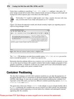
purpose of this book. Figure 6.8 shows an image comparing the AABB and the
OBB in two dimensions:
As shown in Figure 6.8, the OBB has one great advantage over the AABB: It fits
much closer to the object (especially when the object is rotated, as is the case in
Figure 6.8). With the OBB you can build up a much more accurate representation
of the game world.
As explained earlier, an AABB is often described as a MAX and a MIN vector.
These hold the maximum and minimum coordinates of the box in the x, y, and z
dimensions. With an OBB, however, you need one vector with the size of the box,
one vector for its position, and one vector for its orientation. However, in most
physics applications, vectors (Euler angles) are avoided for orientation because of
the Gimbal lock. So instead I’ll use a quaternion for the orientation as covered in
the previous section.
Please purchase PDF Split-Merge on www.verypdf.com to remove this watermark.
THE ORIENTED BOUNDING BOX CLASS
The Oriented Bounding Box (OBB) is a structure that describes a volume with
width, height, length, and orientation. For it to be useful in physic simulations, you
need to be able to perform a number of different intersection tests. Often you also
need to know how far an intersecting object is into the OBB so the physics engine
can handle the collision accordingly. The
OBB class is defined as follows:
class OBB
{
public:
OBB();
OBB(D3DXVECTOR3 size);
bool Intersect(D3DXVECTOR3 &point);
bool Intersect(OBB &b);
public:
D3DXVECTOR3 m_size, m_pos;
D3DXQUATERNION m_rot;
};
120 Character Animation with Direct3D
FIGURE 6.8
Axis-Aligned Bounding Box (AABB) versus Oriented Bounding Box (OBB).
Please purchase PDF Split-Merge on www.verypdf.com to remove this watermark.
At the moment I’ve only defined two intersection tests: one Point-OBB and one
OBB-OBB test. The OBB-OBB intersection test is a bit beyond the scope of this
book. You’ll find a good article on intersection tests online [Gomez99]. You can also
find the code for the OBB-OBB test in Example 6.1 on the accompanying CD-ROM.
However, you need to have a closer look at the more important Point-OBB test. First
consider the point intersection test of an Axis-Aligned Bounding Box (AABB):
class AABB
{
public:
AABB(D3DXVECTOR3 max, D3DXVECTOR3 min)
{
m_max = max;
m_min = min;
}
bool Intersect(D3DXVECTOR3 &p)
{
if(p.x < m_min.x || p.x > m_max.x)return false;
if(p.y < m_min.y || p.y > m_max.y)return false;
if(p.z < m_min.z || p.z > m_max.z)return false;
return true;
}
public:
D3DXVECTOR3 m_max, m_min;
};
The Point-AABB intersection test is very simple; you simply check for each
dimension if the point is smaller than the minimum or larger than the maximum
value of the bounding box. If so, the point must be outside the box. If after check-
ing all the dimensions (x, y, z) none of these tests failed, then the point must be
inside the box. To do this same test for an OBB is not quite as simple because it
also has an orientation. Figure 6.9 shows this problem.
Chapter 6 Physics Primer 121
Please purchase PDF Split-Merge on www.verypdf.com to remove this watermark.
Look at Figure 6.9 and perform the intersection test listed earlier for the AABB.
Now if you try to do the same for the OBB, you would soon realize that it is not
quite as easy to tell whether the points are inside or outside the box using this
method. However, with one simple trick it becomes just as easy to do for the OBB
as for the AABB. You simply need to look at it from a different point of view. Tilt
your head until the OBB becomes an AABB and then check the points using the
same algorithm used for the Point-AABB intersection test. With this in mind,
here’s the code for the Point-OBB intersection test:
bool OBB::Intersect(D3DXVECTOR3 &point)
{
//Calculate the translation & rotation matrices
D3DXMATRIX p, r, world;
D3DXMatrixTranslation(&p, m_pos.x, m_pos.y, m_pos.z);
D3DXMatrixRotationQuaternion(&r, &m_rot);
//Calculate the world matrix for the OBB
D3DXMatrixMultiply(&world, &r, &p);
//Calculate the inverse world matrix
D3DXMatrixInverse(&world, NULL, &world);
//Transform the point with the inverse world matrix
D3DXVECTOR4 pnt;
D3DXVec3Transform(&pnt, &point, &world);
122 Character Animation with Direct3D
FIGURE 6.9
Point intersection, AABB versus OBB.
Please purchase PDF Split-Merge on www.verypdf.com to remove this watermark.
//Check the point just as if it was an AABB
if(abs(pnt.x) > m_size.x)return false;
if(abs(pnt.y) > m_size.y)return false;
if(abs(pnt.z) > m_size.z)return false;
return true;
}
With the OBB structure you can describe some fairly complex (although an-
gular) environments for us to run physics simulations in. In Figure 6.10 you can see
an example of this: on the left side, the mesh used in the rendering pipeline, and on
the right, the physical representation of the same mesh using OBBs.
The mesh being rendered can have thousands of polygons and would therefore
be very expensive to do collision detection with. The OBB representation, on the
other hand, is very fast, without losing too much detail.
Chapter 6 Physics Primer 123
FIGURE 6.10
Example of an environment described using Oriented Bounding Boxes.
Please purchase PDF Split-Merge on www.verypdf.com to remove this watermark.
PHYSICS SIMULATION
Remember that the long-term goal is to create a ragdoll animation and have a
character fall/collide with objects in a realistic way. There’s still a long way to go
before realizing this, although a lot of things have now been covered. You know
how to represent the environment (or at least how to create a simplified version of
it). Now it is time to start looking at the interaction bit.
I guess a quick recap is in order. So far you have learned the theory of rigid bod-
ies, how forces affect an object, the basics of quaternions, and how to describe the
environment using Oriented Bounding Boxes. You will now finally get to put these
lessons into practice. Now it is time to look at how to implement a few physical prop-
erties of a rigid body and how to update (i.e., simulate) these in a realistic manner. In
this book I’ll use the following interface to describe objects in the physics simulation.
124
Character Animation with Direct3D
EXAMPLE 6.1
This chapter has now gone on long enough without a proper code example.
This example implements the OBB class and also shows you an OBB-OBB
intersection test. Try to construct a representation of a cabin like the one in Figure 6.10
using this
OBB class.
Please purchase PDF Split-Merge on www.verypdf.com to remove this watermark.
class PHYSICS_OBJECT
{
public:
virtual void Update(float deltaTime) = 0;
virtual void Render() = 0;
virtual void AddForces() = 0;
virtual void SatisfyConstraints(vector<OBB*> &obstacles) = 0;
};
The Update() function updates the position of the object, the Render() function
renders it, and the
AddForces() function adds forces to the objects such as gravity,
wind, etc. The
SatisfyConstraints() function takes a list of Oriented Bounding
Boxes as a parameter. The OBBs are the physical representation of the world. The
SatisfyContraints() function handles the object’s collision with the world. Next,
there’s the
PHYSICS_ENGINE class, which takes care of a collection of PHYSICS_OBJECT
objects and runs a simulation with these in the physical representation of the world.
class PHYSICS_ENGINE
{
public:
PHYSICS_ENGINE();
void Init();
void Update(float deltaTime);
void AddForces();
void SatisfyConstraints();
void Render();
void Reset();
private:
vector<PHYSICS_OBJECT*> m_physicsObjects;
vector<OBB*> m_obstacles;
float m_time;
};
As you can see, this class contains a vector of physics objects and a list of OBBs.
Each time step, every object in the physics simulation is updated in the following
manner:
1. Add forces (gravity, wind).
2. Update position.
3. Satisfy constraints (check for collisions, and move object to a legal position).
Chapter 6 Physics Primer 125
Please purchase PDF Split-Merge on www.verypdf.com to remove this watermark.